
|
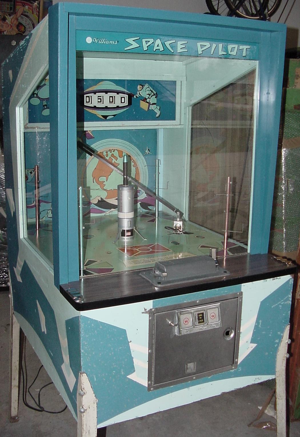
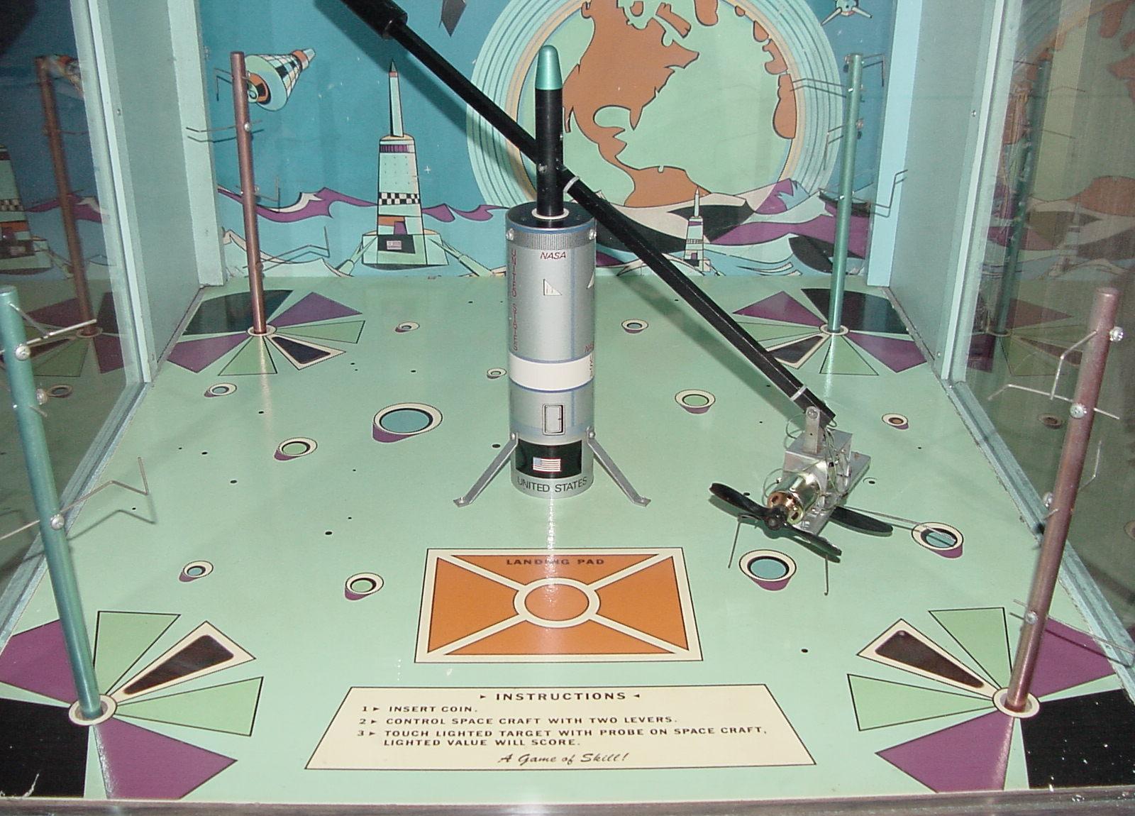
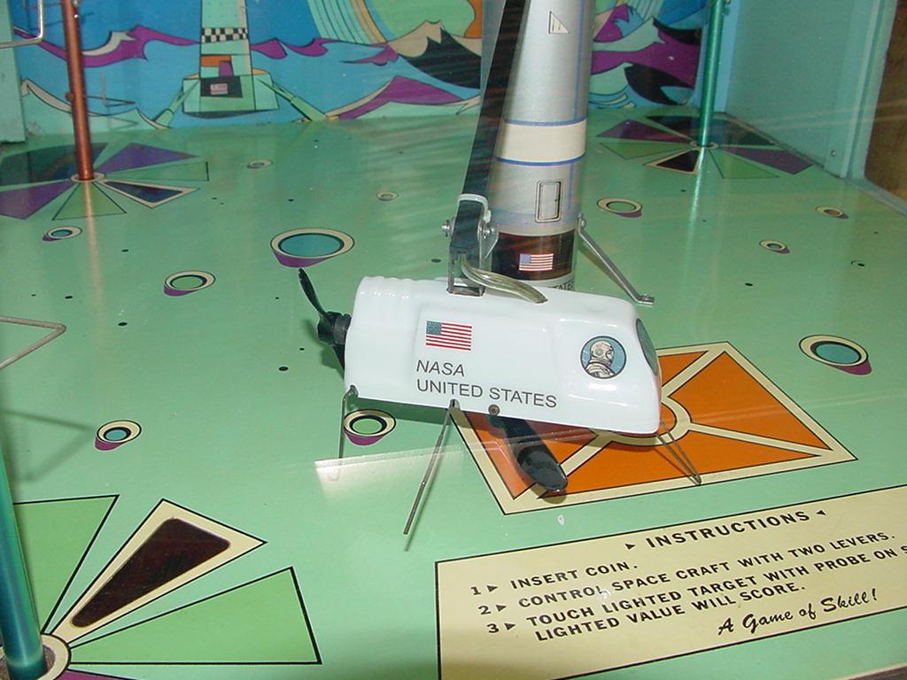
Description: Space Pilot, Williams #364, 11/68. Fly the helicopter-like space craft around in circles, trying to hit the target contacts with the metal "whisker" rod on the bottom of the Space Craft to score points. Very similar to Amusement Engineer's Trainer (1968), Sega's Helicopter (1968) and Midway's Whirly Bird (1969) and Chopper (1974), but Space Pilot obviously has a space theme. Use the left control lever to raise/lower the space craft using a bottom facing motor/propeller. Use the right lever to move forward or reverse using a sideways facing motor/propeller. This is unlike the helicopter games that uses a single motor and single propeller, and the upward facing helicopter propeller tilts forward/backwards to move the copter forward or backward. Space Pilot is a similar concept, just implemented differently using two motors. Fly the craft around hitting the lit target on the four tree towers in each corner that have stiff wires projecting from them (a lit red playfield insert indicates which target to hit). The target towers rotate 90 degrees after scoring that tower, using a solenoid. This rotation changes the scoring for that tower to another wire at a different height and shape. There is a metal spring ("whisker") on the bottom of the craft that makes the contact with the lit target tree. The more targets hit, the higher the score, in a given amount of time (the game time is operator adjustable using an under-the-playfield pot). No electronic sound in this game, though it could really use it.
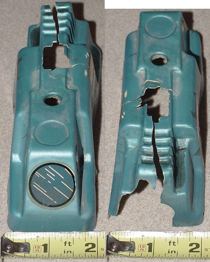
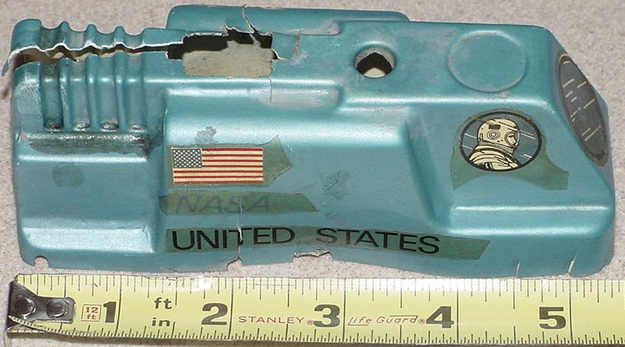
The Space Craft.
Add Background Sound.
|
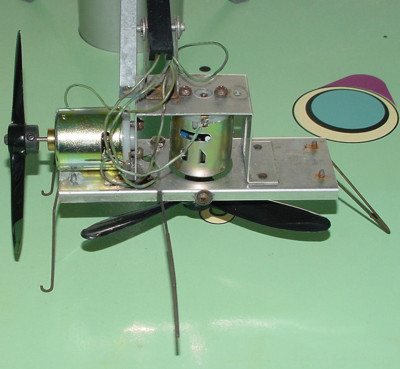
The naked space craft with two new Radio Shack motors installed.
|
REPAIR TIPS: This is a very simple EM style game. There's not a lot here EM wise, just three score reels, a small score motor, and a handful of relays. That stuff is all pretty easy to fix. But the EM side of the game is interfaced to some early electronics, and here things get tougher.
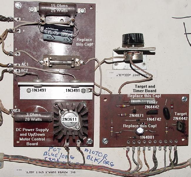
D.C. Power Supply. If either 1N3491 diode is bad, replace both diodes with a 25 amp 400 volt bridge rectifier. Just hook the two A.C. wires to the A.C. leads of the bridge. Hook the "-" of the bridge to the top most lug of the board (black/white wire). Hook the "+" lead of the bridge to the right side of the fuse. Another part that must be replaced is the large 1000 mfd 20 volt capacitor that is connected to the top most large resistor. This 30+ year old cap is dead, trust me! And it is really needed to smooth out the D.C. voltage. Replace this with a higher value too. Back in 1968, electrolytic caps were expensive. Today they are not. I have a 3300 mfd cap connected in the picture below. Any electrolytic cap up to 6800 mfd should work fine.
Up/Down Space Craft Control. The 2N3611 is a PNP GE-AF power output transistor. It is pretty much obsolete. The only replacements I could find was the 2N555 or NTE121 (the NTE was $10). The 2N555 seems to be the better choice, but it's not cheaper. If anyone finds any other replacements, please contact me. Note the user control panel has a maximum stop adjustment for the 5k up/down pot. It may need adjustment, becuase if the up/down lever pushes the pot under about 2k ohms, the up/down motor will spin at full speed, and then just shut off as the lever is moved to the full "on" position. This has to do with how the 2N3611 transistor works with the varying resistance (as the resistance goes down, the motor spins faster, until about 2k ohms is reach; anything under that will shut the motor off completely). So the adjustable range of the pot should be about 5k to 2k ohms. Also the zero position switch in the control panel needs to be adjusted so it just barely opens when the lever is at the zero position. The voltage being varied to the motor hence ranges from 0 to 17 volts.
Motors. On my Space Pilot, the up/down motor was having problems. The 12 volt motor available from Radio Shack #273-255 (or #273-256) for $4 does work and does mount (after taping the motor mounts with a 6-32 tap), but it would be nice to find the exact Mabuchi replacement motor. Though actually that 12 volt Radio Shack #273-255 motor really works well (better than the Radio Shack 9-18 volt #273-256 motor, though the difference between those two Radio Shack motors seems to be minimal). Since an exact replacement could not be found, I decided to take apart my up/down Mabuchi motor and clean it. The brushes easily remove via two springs. Be careful when removing the springs. The spring mount tabs do *not* need to be bent to unlock the springs. If you bend the spring tab, it could easily break, ruining the motor. After the springs are removed, the brush mounts can be unscrewed from the motor. From that I could clean the brushes and the spinning commutator using a "Team Orion" motor commutator cleaning stick #41602 (basically it's a small eraser), available from any decent hobby shop. Amazingly, the motor now worked after I cleaned it, but it ran inconsistently speed-wise compared to the new Radio Shack motor. For this reason, I decided to stay with the new Radio Shack #273-255 motor for the up/down motor. After I installed the new up/down motor, this really made it noticable how worn the forward/backward motor was. For this reason, I also replaced it with a new Radio Shack #273-255 motor. The installation wasn't quite as easy, as the RS motor is slightly larger in diameter than the original Mabuchi motor. I had to grind the aluminum base plate under the motor a bit to get a good fit. But after it was installed, boy what a difference it made. The forward/backward action was *much* faster and more controlled with the new motor. The original small 4" two-blade propeller had no problem moving the craft forward and back. Here's a tip when soldering the new motors in. Don't let the motor's solder lugs touch the aluminum space craft frame after the wires are soldered. If one does, Space Pilot will freak out when a game is started, automatically scoring and then ending the game right after that.
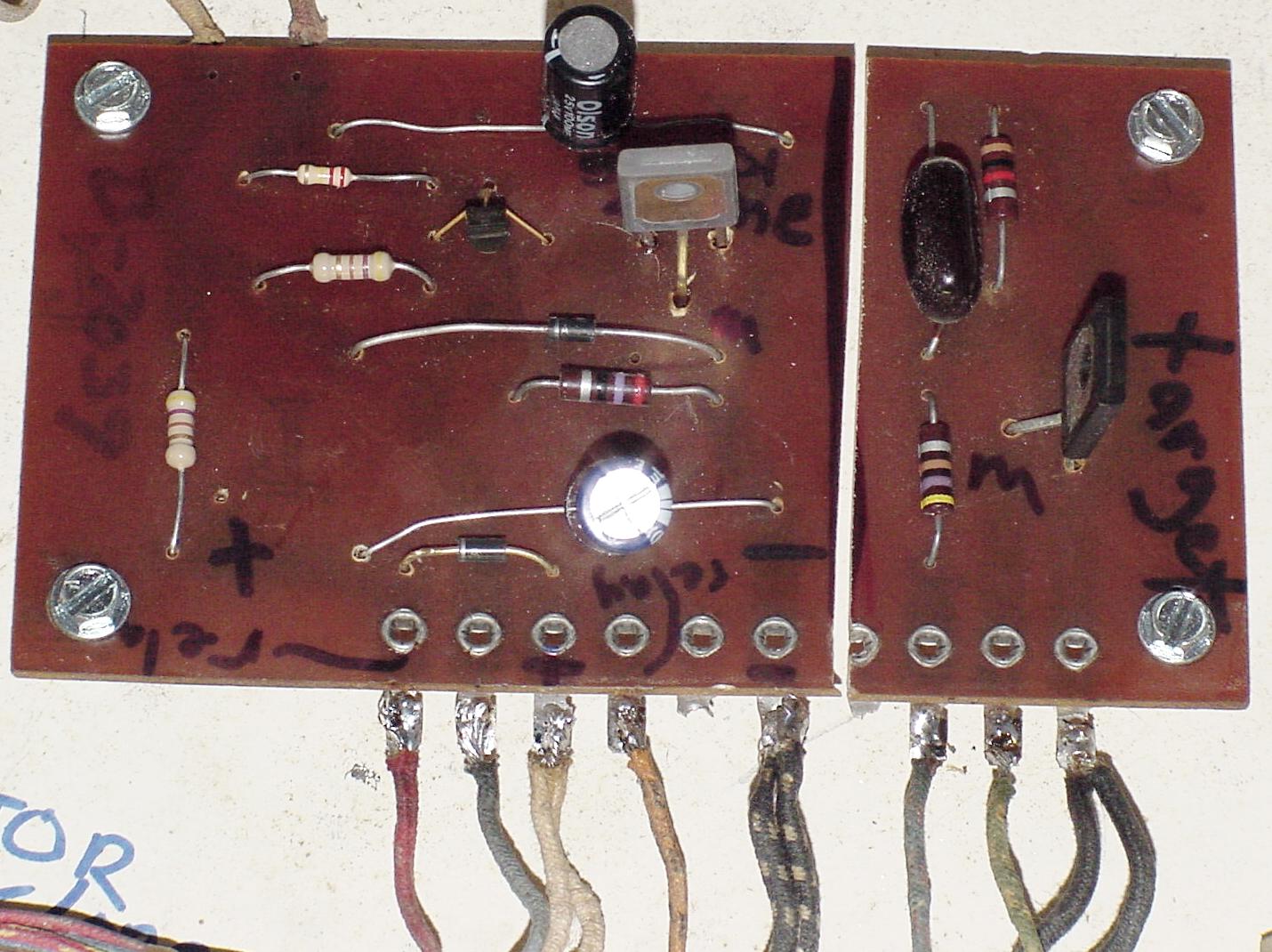
Game Timer Board. The timer board works on 12 volts D.C., not the 17 or 18 volts D.C. that is feed to it. To bring the power down to 12 volts, a 1 watt 1N4742 zener 12 volt diode is used (there is also a 1N4001 diode used in the circuit too). Though the 1N4742 diode doesn't seem to go bad, it's a good idea to check it. Both diodes will need to have one lead removed from the board to test it with a DMM's diode function and the power off (they don't test properely incircuit). Also with power on to the timer board, a DMM can be used with the red lead on the banded side of the 1N4742 diode, and the black lead connected to the black/white wire board lug. About 12 volts DC should be seen. Remember if replacing these, the bands of both diodes face away from the SCRs. Note the timer board also has two electrolytic capacitors: a 500 mfd 25 volt filter cap, and a 100 mfd 25 volt. Again, these will be dead and should be replaced with a new ones. On my game the 500 mfd 25 volt filter cap was bubbled at the end and leaking. Remember when replacing these the negative lead of the caps face towards the target SCR. Also it's not a bad idea to check the values of the resistors. There are two 470 ohm resistors, and on my board they read 650 ohms (which is way out of spec). I replaced mine with new 1/4 watt versions. The 220k resistor was also way out of spec too. If the game goes on forever with no time limit, the timer board has a problem. This could be the 2N4442 (or 2N4441) silicon controlled rectifier (SCR) on the timer board. Note there are two of these, but only one controls the game time. These are also largely obsolete, as I guess there's not much call for a 8 amp 400 volt SCR (or 8 amp 50 volt for the 2N4441). The only relacement I could find was the NTE5448 (or NTE5442 for the 50 volt version). But at $21 and $16 respectively, it's not a very good replacement! I tried the Bally T106 SCR (4 amps 100 volts) it is does work and installs in the same manner (metal face inward towards the 1N4742 diode). The T106 SCRs are common and around $1 each, but I am not sure how long this whimpier SCR will last. Remember when replacing this SCR, the metal front faces inward towards the 1N4742 diode. Other potential problem is the small and funky 2N4871 transistor (TO-92 package). Another obsolete part, the only replacement I could find was the NTE6410. This hard to find $5 part is a "unijunction", which means it's a unilateral 1 amp switch. The unijunction transistor (UJT) is a three terminal device with characteristics very different from the conventional bipolar transistor. It is a pulse generator with the trigger or control signal applied at the emitter (center leg). To test the UJT is pretty easy using a DMM set to DC volts. Put the black lead of the DMM on the black/white wire lug (ground) of the timer board. Then put the red DMM lead on the UJT's center lead. Turn the timer potentiometer all the way to "minimum". Apply power to the board (manually depress the Game relay next to the score reels so it is energized). Now watch the DMM. The DC volts should go from about 1 volt progressively up to about 9 volts. When about 9 volts is reached, the SCR on the timer board is triggered, and the Game Over relay under the playfield is pulsed (which turns power off to the Game relay next to the score reels, and then powers off the timer board). If the timer pot is turned up to "max" time, the rate at which the DMM voltage increases at the UJT slows down. As the UJT voltage is going up on the DMM, play with the timer pot to verify the increase slows down as the pot time is turned up. If the voltage does not go up at all, the UJT is bad. If the UJT gets to 9 volts and the Game relay does not pulse, the timer SCR is bad. The UJT emitter terminal does not inject current into the base until its voltage reaches a certain level. Once reached, the base circuit (B1/B2) conducts and a postive pulse appears at the B1 terminal and a negative pulse at B2. This then feeds to the 2N4442 SCR (and ultimately completes the power path and energizes the "game over relay", ending the current game). When replacing the 2N4871, the round side of the IJT faces towards the 1N4742 diode. There is one more possible problem that could occur with the timer board. This relates to the blue wire that connects to the board, right below the 1N4001 diode (second wire lug, next to the red/brown wire). This wire goes up to the Game relay next to the score reels, and completes a path from DC ground to the Emitter of the 2N4871 on the timer board. When the Game relay energizes, this path to ground is broken, and the 2N4871 starts it's timing cycle (with the Emitter's voltage increasing up to 9 volts). If for some reason the switch on the Game relay never opens, and the ground path to the 2N4871's Emitter is maintained, the 2N4871 will never start it's timing cycle, and the timer board will never work! This can make the 2N4871 or the SCR look as though it is bad, when in fact it is not. If you want to verify this is the problem, temporarily unsolder the blue wire from the timer board, and test for the increasing voltage at the 2N4871's Emitter (as described above). This ground path is basically an on/off switch for the 2N4871, as a good way to turn the timer board off and on (even though power to the board is also turned off via the Game relay, making this switch somewhat redundant).
Target Scoring.
|
The schematic below shows the power supply and up/down motor circuits inside the
red lines (the dotted red line splits the power supply and up/down motor circuits),
both contained on the D.C. power supply board.
The blue lines show the timer and target hit circuits, both contained on the timer board
(the right most blue circle is the target hit circuit).
|
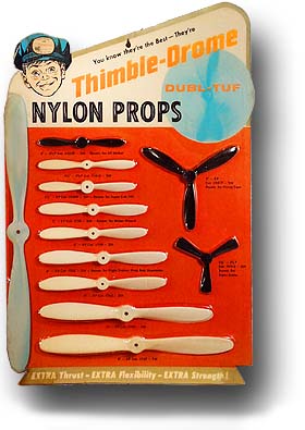
Propellers. The space craft's propellers can break, so replacements need to be found. The original propellers were black Cox "Thimble-Drome" nylon propellers (the propeller picture below is a 1958 card display). The up/down propeller was a 3-blade type. Three blade propellers don't offer any performance enhancements over 2-blade propellers, but they do allow the blade length to be about 20% shorter. This is important for added clearance, and that's why the three blade propeller was used for the up/down motor. The other thing about both propellers in this game is they are "pusher" type propellers. This is an important aspect of the propeller, as the blades have a different shape than "tractor" propellers. I found the three blade Cox propellers at www.hobbypeople.net/mfr/cox01.asp, Cox# 994 "Cox 5D x 3P (5" diameter) nylon prop 3-blade RH" (part# 392266, $2.59). This is the exact replacement blade for the up/down propeller installed in my Space Pilot game. Cox also has a "5D x 3.5P" 3-blade #7508 propeller, but that one is "reversed" compared to the original and is not a proper replacement. The new propeller has the markings "5D 3P" on it, which means 5" diameter (5D) and "3P" for pusher (3" of forward movement for each revolution {not factoring slip, efficiency, etc.}, "P"usher style). For the up/down motor nothing larger than 5" in diameter/length can be used, otherwise the blade hits the space craft's legs. For the forward/backward propeller, it too seems to be a "pusher" type. It is only 4" in diameter/length, and can not be any longer (or the propeller will hit the playfield when the craft is at its resting position). A two-blade or better yet a 3-blade propeller can be used (my game has a four inch 2-blade propeller, and it appears to be stock). This is Cox "4D x 2.5P" prop (I don't have a current Cox part number). Also perhaps a five inch "5D x 4P" Cox #759 two blade prop could be used and cut down 1/2" on each blade. After a replacement propeller is found (the Cox Thimble Drome propellers are often still available at many hobby shops), the original metal mount must be removed from the old propeller and reused. Just heat up the metal propeller mount with a soldering iron or a heat gun and pull it out of the old propeller (the metal mount has "spines" on it to hold itself to the nylon propeller). To mount it to the new propeller, again heat up the metal mount and gently hammer (or squeeze it in with a vice) on the new nylon propeller.
|
|
* Email the collector cfh@provide.net * Go to the EM Arcade History index * Go to the Pinball Repair/History index |