Granny and the Gators
Pinball/Video game
07/02/25
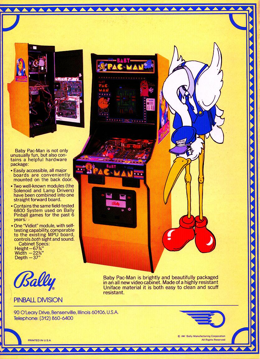
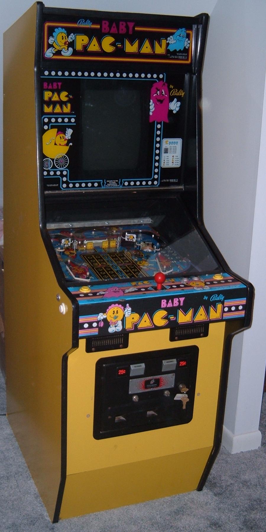
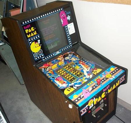
Description: Bally Baby Pacman Bally, 1981, uses Bally -133 MPU board. Bally Baby Pac. A combination of pacman video game and a small pinball playfield. A merge of pacman video and pinball. 7000 Baby Pacs were made. Caveman (Gottlieb System80) and Baby Pac-Man were the first games to combine video games and pinball (Caveman was implemented differently though).
Granny and the Gators followed Baby Pacman and is the same design, but different game play (and not nearly as fun as Baby Pac). Granny used an updated Vidiot board called the "Vidiot Deluxe" board. This used an addition TMS9928 chip (two instead of one on Baby Pacman) and had addition RAM and ROM. Also the boot up flash code sequence is different on the Vidiot Deluxe, due to the additional circuitry.
If you have a Bally Baby Pacman or Granny and the Gators for sale, please contact me at cfh@provide.net
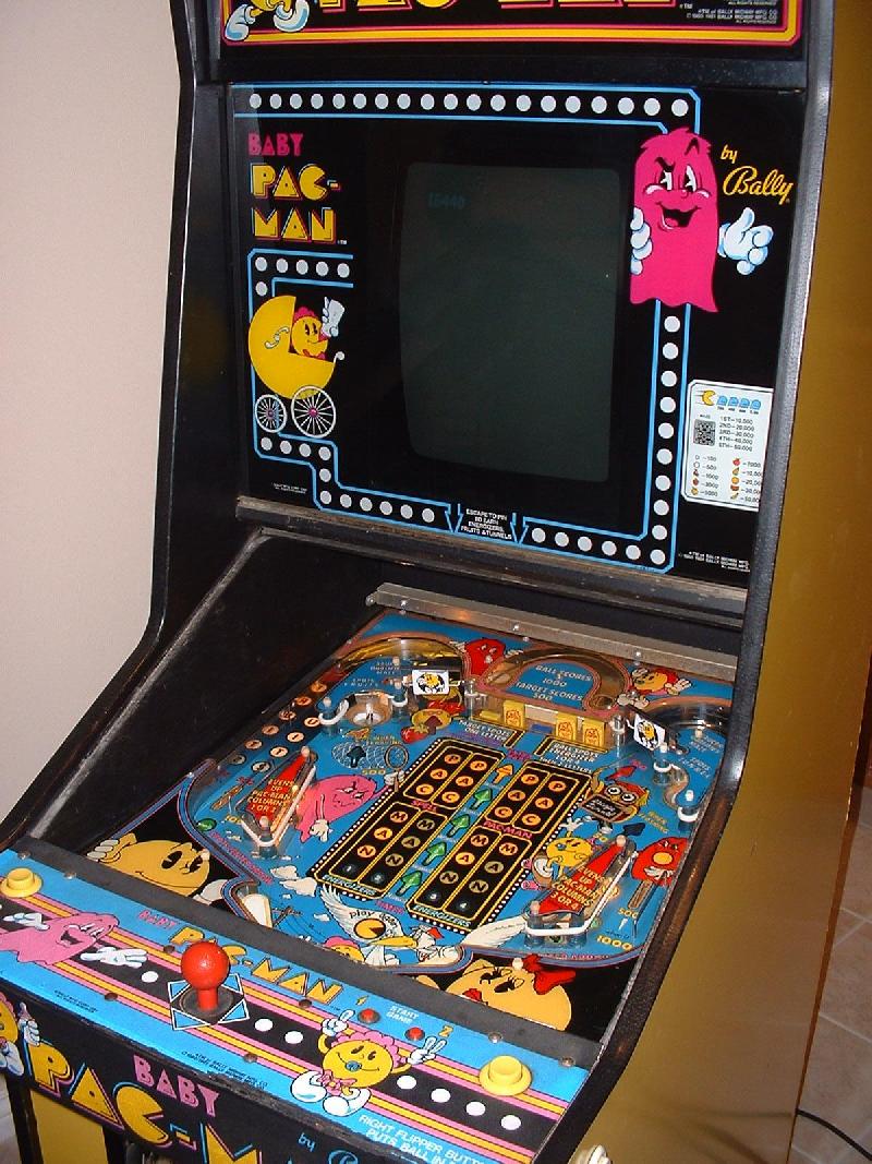
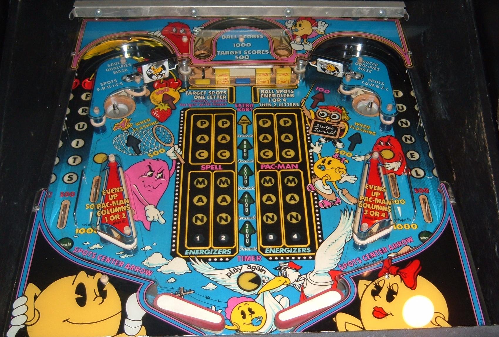
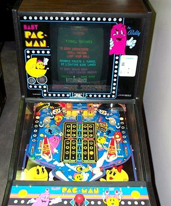
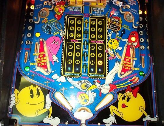
Baby Pacman starts off in video game mode. Run around the maze and eat all the dots. There are two outlanes at the bottom of the 13" Wells-Garner monitor, which allow you to escape and play pinball. There are no power pellets in the video game to save you. And the ghosts are all very intelligent, unlike the arcade video game. It is difficult to stay alive in the video game portion (I would sure like a "home ROM" version were I could not die in the video game part). It is entirely possible to lose all your lives (three is the default) in the video game section and never play any pinball. The best playing approach is to get out of the maze as fast as possible. This is done when you go down one of the open tunnels at the bottom. This will put you into the pinball part of the game.
There are a few pinball targets which help unlock power pellets in the video portion. The only way to lose the ball is down the middle drain, which will put you back into the video game, but now the escape tunnels are closed (you are forced to stay in the video mode). The only way to unlock the escape tunnels is to complete the current video screen (eat all the dots). Hopefully you unlocked some power pellets.
Technical Repair.
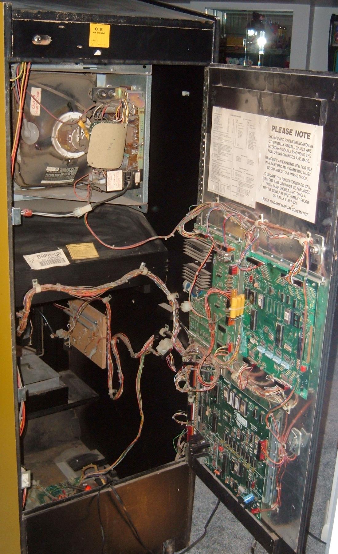
Fixing Baby Pacman can be a challenge. But with some simple "break the system down" thinking, it's not too bad. The AS2518-133 MPU board is basically a very slightly modified Bally -35 MPU board. Repair help on that can be found at pinrepair.com/bally. This MPU board controls the pinball functions of Baby Pacman. The "Vidiot" AS-2518-121 board handles the video game portion of the game. These two board must communicate, and this is typically where problems often lie. The Vidiot and MPU board must communicate together or the game will never start-up or work properly. This is probably the biggest problem of fixing a Baby Pacman is communication problems between the MPU and Vidiot boards.
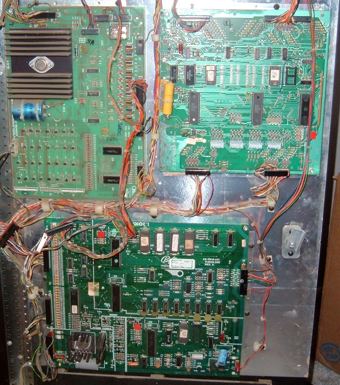
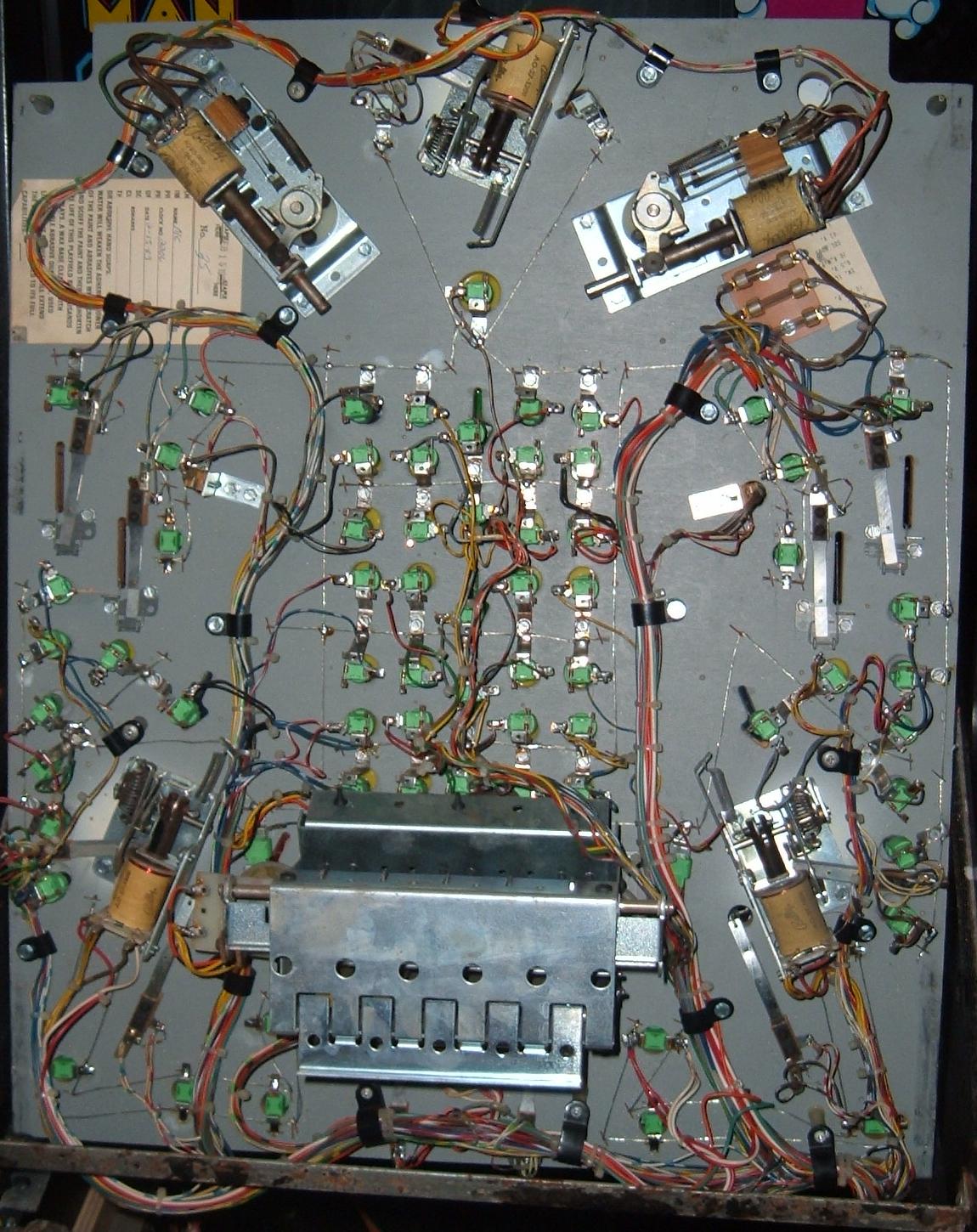
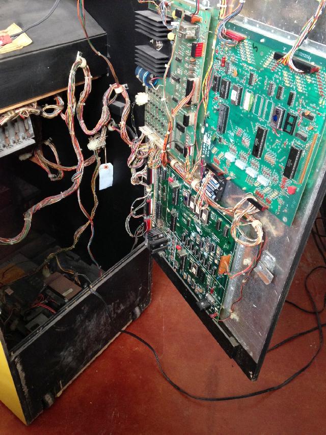
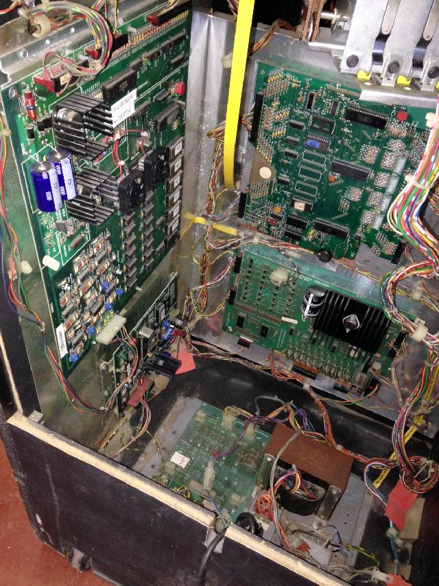
The boards inside a Baby Pacman machine.
MPU Board Battery Corrosion.
There is a rechargeable nicad battery on the MPU board
which often leaks. This can cause all kinds of problems
with the MPU board, and even the Vidiot board (which is
mounted right below the the MPU board and the battery).
Remove this battery ASAP and discard. Aside from ruining
the MPU board, it can also spread its corrosion down
the center section of the Vidiot board, all the way to
the lower sound section of the board! Of course the .100" connector
pins will be ruined in the process, not to mention the
Vidiot board traces and its components. A remote mounted three "AA"
battery pack with a blocking diode is suggested as a good
MPU board battery replacement.
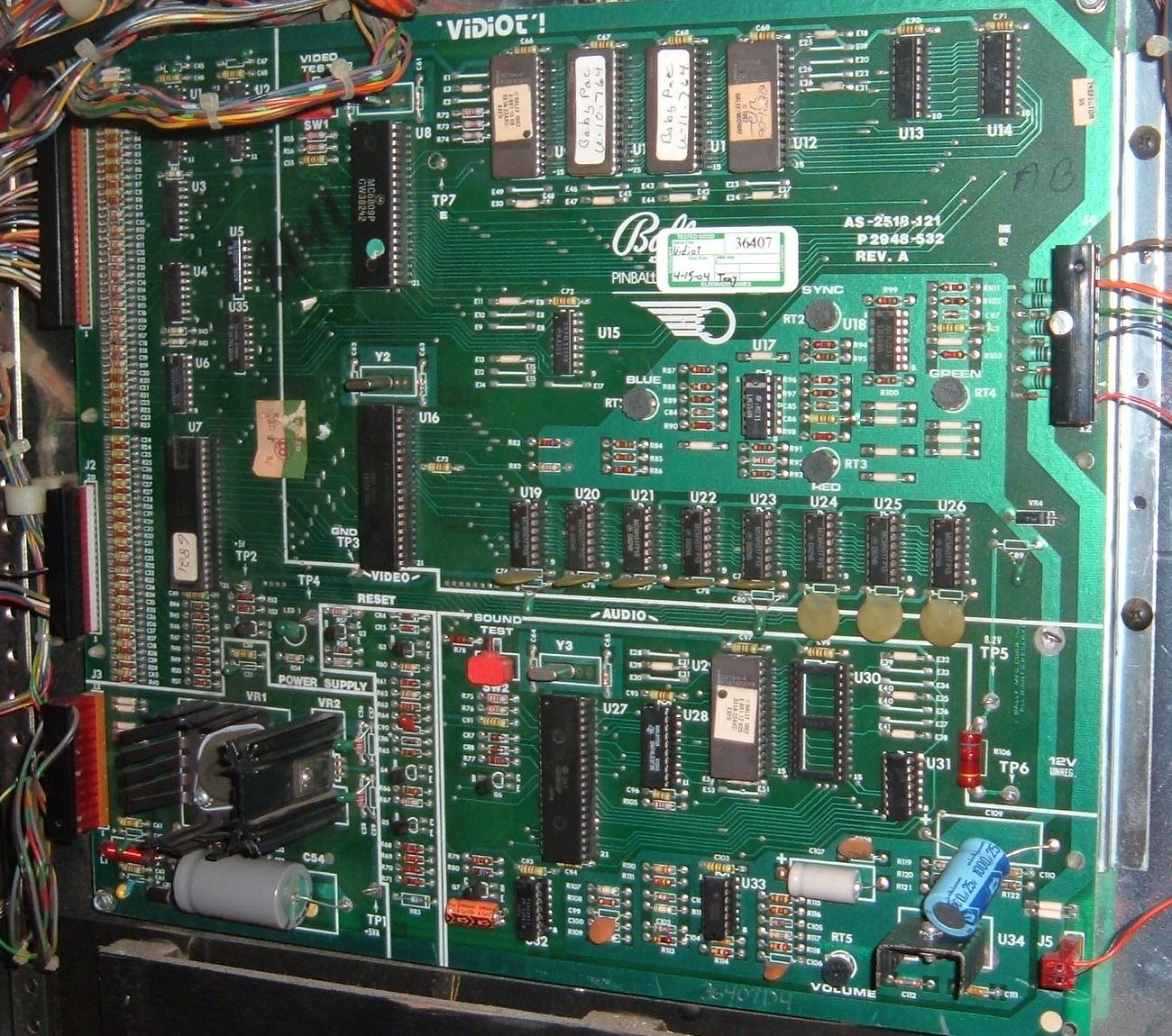
Vidiot Board Explained.
The Vidiot board has several circuits and two microprocessors. A 6809 at U8
is used for the video game chores, and a 6803 at U27 is used for the sound system.
These are two different computer systems with different functions.
The vidiot board also has a separate communications circuit for
moving data between the pinball MPU-133 board and the Vidiot board.
This is done through the MPU-133's switch matrix and a
Vidiot 6821 PIA at U7. The Vidiot PIA also interfaces the player
joystick to the game.
The vidiot board also has its own power supply. It uses 12 volts DC unregulated (4 amps) to create +5 volts through two different voltage regulators. One smaller voltage regulator (VR2, 7805) supply 5 volts for the sound section, and the other larger voltage regulator (VR1, LM323) supplies 5 volts for the rest of the board. The unregulated 12 volts is also used for the sound amplifier. In addition 8.2 volts (VR4, 1N5344 5 watt 8.2v Zener diode) is used Video Amp Dematrix. The Baby Pacman Vidiot board does *not* use the +5 volts generated by the lamp/solenoid driver board! The audio amplifier also uses the unregulated 12 volts DC.
There are several test points on the Vidiot board. Check them for the appropriate voltages:
- TP6 = 12 volts DC unregulated
- TP3 = Ground
- TP2 = +5 volts DC
- TP5 = 8.2 volts DC
Just like the MPU board, there is a reset section on the Vidiot board. This provides a 100 millisecond wait time for the +5 volts to stablize. This is done by holding the 6809 U8 processor, 6803 U27 processor, and 6821 U7 PIA reset lines low (0 volts) for 100ms. The components for this reset include zener diode VR3 (1N958B or 1N4738a, 7.5 volt) and transistors Q4 (2n4403) and Q5 (2n3904). If the Vidiot board is getting *no* flashes (and the above voltages check out and the LED is good), check the reset lines on the processors to see if it is high. Use a DMM and check for 4.5 volts at U8 pin 37 (6809), U27 pin 6 (6803), and U7 pin 34 (6821 PIA). If all are zero volts, the reset circuit is not working (all three chips should have their reset either high or low, if you have a mixed bag, there is a broken trace). If reset is low, check Q4 and Q5 and VR3. If the voltage is 4.5 volts, then I would next suspect an EPROM as bad (or a broken trace going to the EPROMs), or possibly the clock circuit (check 6803 U27 pin 10 for a clock signal using an oscope). I believe the Vidiot board initially boots from the EPROM at U29, so check that EPROM first.
Lastly the Vidiot board has a video game section, broken into sub-sections. One sub-secton includes the 6809 video game processor at U27, the address decoder, and the program RAM/ROM. The communications interface forms another sub-section. The last sub-section is the video display processor (TMS9928 at U16), video RAM, and video amp dematrix.
The communications interface consists of U1,U2 (74LS374), U3,U4 (4050), U6 (74LS368), and U7 (6821 PIA). These chips work with the 6809 processor at U8 to provide MPU-to-Vidiot communications, vidiot switch reading, and video-sound processor communications. The vidiot has its own switch matrix of four strobes by eight returns (28 switches total).
The video display process at U16 is a TMS9928 40 pin chip. This processes all video, control and sync signals, and storage/retreival of data from the dynamic screen memory (VRAM at U19-U26). It can output 15 colors and 32 objects (sprites) with a minimum of programming overhead. The 6809 at U8 communicates with the TMS9928 to accomplish this. The video amp dematrix converts the video signals to Red/Green/Blue and Sync for the color 13" monitor.
The sound section of the Vidiot board has two sub-sections. The sound 6803 microprocess at U27, its bus demultiplexor, address decoder and program ROM form one sub-section. The EPROMs at U29 and U30 are the sound EPROMs (but only U29 2764 is used for Baby Pacman). The D-A (digital-analog) converter, low pass filter and power amplifier form the other sub-section.
No Video or Bad Video.
Even though a Vidiot board gets 10 flashes on the diagnostic LED,
it can still have problems and not work. A common failure is to
have absolutely no video output at all. Assuming the 13" monitor
is working, the first thing to suspect is the TMS9928 chip at U16,
as this 40 pin chip is very problematic. If this chip is having problems,
often the video will be distorted or won't sync properly. But you will
usually have some kind of video.
The TMS9928 chip outputs the video signals directly to two video amplifiers, LM359N at U18 and U17, and then goes to the output video plug at J4. If either or both LM359N chips are bad, you will either get absolutely no video, or video that won't sync. These video amplifier chips do fail (just repaired a Vidiot board where the TMS9928 was fine, but both U17 and U18 LM359N chips were bad).
Also note the video signal passes thru a number of resistors around the LM359N video amplifiers. If the colors are strange or won't sync, check these resistors. In particular there are three 100 ohm 1/2 watt resistors than often go open (R89, R97, R102). You will have to remove one end of the resistor from the board to test with a DMM. Also the three 3.9k resistors (R101, R96, R88) mounted just above the 100 ohm resistors should be checked too.
The pots for the colors and sync also go bad often. The green and sync are 10k ohms, and the red and blue are 2.5k ohm pots. Replacement is a good idea.
Video ground is another problem. There is a large ground plane on the front and back side of the Vidiot board. Make sure these two ground planes "buzz out" and have continuity with each other (a small jumper may be required to ensure this). Also if the video is over-saturated with blue or red, there may be a problem with the video signal ground at J4 pin 2. The factory often has a capacitor going from Vidiot J4 pin 2 to ground. If red and/or blue are over-saturated, replace this resistor with a jumper from J4 pin 2 to ground. This should fix the saturation problem.
Also check the two 74LS374 chips at U1 and U2 as these are problematic too, though this may not reflect directly in the video signal.
Vidiot TMS9928 Heat Problems (Heat Sink).
The TMS9928 chip at U16 on the Vidiot board which handles the
color generation for the video monitor can get very hot.
At minimum it should have a heat sink. Or in addition a
small 12 volt fan to keep it cool. If your Baby Pac runs
for 15 minutes and then dies, an over-heated TMS9928 chip
is most likely the problem.
The easiest heat sink to use is a 40 pin DIP slide-on black anodized heat sink. DigiKey sells a slide-on version, part number HS183-ND, which dissipates 1 watt of heat. They also sell a glue-on version, part number HS274-ND, which dissipates 2.5 watts of heat.
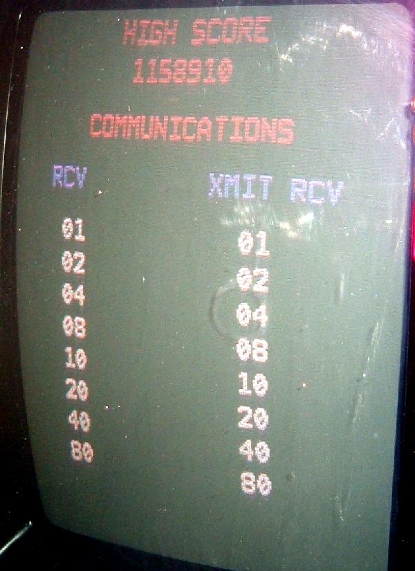
Here a proper Communications Test screen in a working Baby Pacman.
Vidiot Test Button SW1.
The Vidiot board has a test button (SW1), which is at
the top of the Vidiot board.
Allow the Vidiot board to flash its
LED the full 10 times (which signifies the board has
booted correctly). Then press the Vidiot test button once.
If the MPU board has also booted, and the Vidiot board
can communicate with the MPU board in any way,
The "communications test" should come up.
This is the same communications test that is
run using the coin door's red test button (see below
for more information on the Communications Test).
If the MPU board does not boot (or is not connected),
pressing Vidiot SW1 once should bring up either the Communications test
(with no Xmit/Rec info), or the color bar test. If the Communications
test comes up, press SW1 again for the color bar test.
The color bar test puts color bars on the 13" video monitor
(allowing adjustment to the Red, Green, Blue, Sync trim
pots on the Vidiot board for proper colors).
Remember if pressing Vidiot SW1 once brought the communications test up, pressing SW1 a second time will bring the color bar test up.
Note the MPU (S33) test button is not helpful for diagnostics.
Communications Error.
If the Vidiot board LED flashes ten times, but there's no attract mode
video, there may be a communications problem between the MPU and Vidiot boards.
Press the red test button inside the coin door once, and the communications test
screen should appear (see picture above.) Note the "RCV" and "XMIT" numbers
for each row *must match*!! If they do not, there is a communications issue.
The game will not operate until this is repaired.
The communications interface on the Vidiot boards consists of U1/U2 (74LS374), U3/U4 (4050), U6 (74LS368), and U7 (6821 PIA). I have found the most common issue is U1/U2 and/or U3/U4. If you have a scope this is helpful. But often just replacing U3/U4 first, then U1/U2 will often fix a communications error. Also don't forget to check Vidiot board connector J1, as it's a .100" IDC style connector. Sometimes wires get compromised on small IDC connectors...
Vidiot Test Button SW2.
In the middle of the Vidiot board is another test button SW2.
After the Vidiot board boots, pressing this button should
produce a short electronic space sound, and the Vidiot LED
should flash twice. The LED flashes just twice because at
power-on the first two LED flashes are related to the
sound section. So pressing SW2 is just running this
portion of the power-on LED code.
The two LED flashes shows the sound CPU is running correctly.
Tilts Causing Problems.
If the ball roll tilt or plumb bob tilt is stuck closed (or the capacitor
on the tilt internally shorted), this can cause issues on Baby Pacman.
For example, pressing the test button on the Vidiot board to show the communications
test will indicate no numbers. However, if the red test button on the coin
door is pressed, the communications test is shown with the correct numbers. When
a game is started it will show the Use Joystick to Complete Maze screen and play the
Pac Tune, then it will freeze on that screen. So check the roll tilt and plumb bob
tilts to make sure they are not closed.
Testing the Vidiot Board "on the bench".
The Vidiot board can be tested without the rest of the
game and on the work bench. All that is needed is 12 volts DC.
Ideally it would be nice to have a video game monitor and speaker too,
but it's not completely necessary. Here's the connectors
needed to boot the Vidiot board outside of the game.
-
VJ3 - Power & ground (12 pin .156" molex connector):
- Pin 1,2 = 12 volts DC
- Pin 7,9,11 = ground (all three pins must be connected to ground)
- Pin 2 = ground
- Pin 3 = sync
- Pin 5 = green
- Pin 7 = blue
- Pin 11 = red
- Pin 1,2 to speaker.
- TP6 = 12 volts DC
- TP3 = Ground
- TP2 = +5 volts DC
- TP5 = 8.2 volts DC
VJ4 - Video (optional, 12 pin .156" molex connector):
VJ5 - Speaker (optional, 2 pin .156" molex connector):
Be sure to check the power voltages with your work bench test rig: Use the test points on the Vidiot board.
With power connected, the Vidiot board should flash ten times (flash codes are shown below), and the studder/abbreviated Pacman tune should play during bootup (assuming a speaker is connected to J5). After the ten flashes, pressing SW1 will bring up the either the Communications test (with no Xmit/Rec info), or the color bar test. If the Communications test comes up, press SW1 again for the color bar test. Of course both of these test are useless unless there is a video monitor connected. Pressing SW2 will play a short electronic space sound and the LED will flash two times.
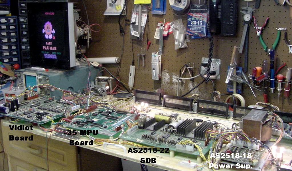
At this point you can take this one step further and build a harness that will connect the Vidiot board to a -35 (or -133) MPU board. I have a Bally test fixture that I made, which runs a -35 (or -17) MPU board through a standard AS2518-18 power supply and a AS2518-22 (or AS2518-17) solenoid driver board. I can put Baby Pacman U2 and U6 2732 EPROMs in the -35 MPU board, disconnect the Bally lamp driver board and connect the Vidiot board VJ1 connector to the MPU board's J1 and J2 connectors. I connect a video monitor to the Vidiot board's VJ4 connector and boot up the test fixture. Baby Pacman will boot and go into attract mode on the video monitor. Pressing the standard Bally coin door switches I can add credits, start a game or go into diagnostics. If I have a joystick connected to the Vidiot VJ2 connector, I can play Baby Pacman on the test fixture! I just can't play the pinball part (no playfield).
All the diagnostic tests will run except for the Lamp test. This including the solenoid test running through a pinball AS2518-22 or -17 solenoid driver board. The communications test will also run correctly showing the proper communications between the Vidiot and MPU boards (assuming the harness made is wired correctly). Note I am *not* using a -133 MPU board on my test fixture. Since my fixture provides 43 volts DC to MPU J4 pin 15, connecting a -133 would damage the MPU board ( the -133 MPU expects 6 volts AC at J4 pin 15). This "zero cross" circuit is used for the CPU controlled lamps on Baby Pacman. In fact, they use one 2N5060 SCR to control two different lamps, depending on the phase of the zero crossing (this was also done on the Bally 6803 system).
Here is the connector harness needed to make the communications test work between the MPU and Vidiot board:
- VJ1 pin 3 - MPU J2 pin 9 #
- VJ1 pin 4 - MPU J2 pin 8 #
- VJ1 pin 5 - MPU J1 pin 5
- VJ1 pin 6 - MPU J1 pin 6
- VJ1 pin 7 - MPU J1 pin 28
- VJ1 pin 8 - MPU J1 pin 27
- VJ1 pin 9 - MPU J1 pin 26
- VJ1 pin 10 - MPU J1 pin 25
- VJ1 pin 11 - MPU J1 pin 23
- VJ1 pin 12 - MPU J1 pin 22
- VJ1 pin 13 - MPU J1 pin 21
- VJ1 pin 14 - MPU J1 pin 20*
- VJ1 pin 15 - MPU J1 pin 7
- VJ1 pin 16 - MPU J2 pin 12
- VJ1 pin 17 - MPU J2 pin 11
- VJ1 pin 19 - MPU J2 pin 13
- VJ1 pin 20 - MPU J2 pin 10
- VJ1 pin 22 KEY
- VJ1 pin 23 - MPU J2 pin 14
- VJ1 pin 24 - MPU J2 pin 9 #
- VJ1 pin 25 - MPU J2 pin 15
- VJ1 pin 26 - MPU J2 pin 8 #
# This single VJ1 pin goes to TWO mpu board connector pins.
If you would like to hook up a joystick to the Vidiot board, here's the pinout for that:
- VJ2 pin 2 - Joystick Up
- VJ2 pin 3 - Joystick Down
- VJ2 pin 4 - Joystick Left
- VJ2 pin 5 - Joystick Right
- VJ2 pin 10 - Joystick switch strobe
The author's test fixture with a -35 MPU and a Vidiot board running Baby Pacman:
Communications Test.
If the Vidiot board has booted with 10 LED flashes, and the MPU
board has booted with 6 LED flashes, the communications test can be run.
Press the red test button inside the coin door
(or SW1 once on the Vidiot board) and
the "Receive/Transmit" screen (Communications Test) should show on the monitor.
The screen above is what it should look like,
showing a sequence of "01,02,04,08,10,20,40,80" in
both columns. If you only have
numbers in one column, or the numbers don't match, or the numbers
aren't 1,2,4,8,10,20,40,80, then the
MPU and Vidiot boards are not communicating properly. Usually
this is a connector problem (.100" Molex connector pins on the
Vidiot board VJ1 and the MPU board J1 and J2 connectors).
Often this is due to battery corrosion from the MPU board (which
mounts above the Vidiot board, and the corrosion spreads downward).
Or sometimes it is the chips in the upper left hand corner of
the Vidiot board at U1,U2 (74LS374) and U3 (4050).
If things are really messed up, also U4 (4050) ,U6 (74LS368) and U7 (PIA 6821)
can cause communications problems.
Worse case, it is the TMS9928 at U16 (40 pin chip) that
is bad (but usually a bad TMS9928 chip would give
no video output on the monitor). This chip is hard to find.
Coin Door Red Button Diagnostic Tests.
After pressing the red coin door test button once and viewing
the communications test, there are other tests:
- 1st Test Button Press: communications test. See above.
- 2nd Test Button Press: pinball lamp test. All CPU controlled lamps are flashed on the pinball playfield.
- 3rd Test Button Press: pinball solenoid test. Each playfield
coil is pulsed one at a time. The coil number pulsed is shown on
the monitor. Holding both flipper buttons in during this test will
show some information on the monitor. Reference: top most TIP102 transistor
on the driver board is Q40 (goes downward sequencially)
- 01 Q37 = outhole
- 02 Q36 = 5 bank drop target reset
- 03 Q35 = #1 drop target release (left side)
- 04 Q34 = unused (originally going to be drop target #2)
- 05 Q33 = #3 drop target release (center)
- 06 Q32 = unused (originally going to be drop target #4)
- 07 Q31 = #5 drop target release (right side)
- 08 Q40 = K1 flipper enable relay
- 09 Q39 = left side saucer kickout
- 10 Q38 = right side saucer kickout
Note on the "unused" #4 and #6 solenoid test the solenoids do not actually fire (because they are not installed). So if wires are connected from the Driver board to playfield solenoids, they should energize these coils (at least in test).
- 4th Test Button Press: sound test.
- 5th Test Button Press: pinball switch test. Any closed switches are shown on the 13" video monitor. If no closed switches, a "0" is shown on the monitor.
- 6th Test Button Press: game audits. All test button presses from here are game audit information. After all the audits, pressing the red coin door button again will reboot the game and says "SLAM" on the video monitor.
Power-On Sequence and LED Flash Codes.
Keep in mind that the MPU board's LED will flash six times
at power-on. Likewise, the Vidiot board's LED will flash ten times.
If either or both boards' LEDs flash less than that, there is a
problem on that board and the game will not start. For MPU board
problems see
pinrepair.com/bally. For Vidiot board problems
see below.
Also the game plays a sick-sounding short pacman tune at power-on. Then the game goes into "attract mode" with the pacman-ish attract mode screen on the 13" video monitor. If either the MPU or Vidiot board's LEDs do not flash the appropriate amount of times, the game will never start. If there is a communications problem between the MPU and Vidiot boards the game will never start.
Baby Pac DIP Switches.
IMPORTANT: make sure dipswitch 16 on the MPU board is OFF, or the game will not start.
There are some other MPU DIP switches which should be documented:
- Sw 30: Free Play (On=Free Play)
- Sw 14: after ball is ejected 3 times without scoring ball is not lost=On.
- Sw 31/32: number of pacmen per game.
5=On Off
4=Off On
3=Off Off (most common setting)
2=On On - Sw 27: credits displays (On=Yes)
- Sw 16: playfield/video adjustment. OFF=playfield works with video. On=playfield only. Make sure this switch is set to OFF.
- Sw 22/23: mazes to complete to get special.
Off Off=complete 3 mazes
On Off=complete 4 mazes
On On=complete 5 mazes
Specials are set using the game's red button inside the coin door. Special Options=02 will award a "Play Again" (extra man). 03=reward a replay, 01=novelty (points), 00=no award.
High score to date function is also set using the game's red button inside the coin door. Hi-Score set to 02 or 03 will award a "play again" (extra man), 01=50k points, 00=no award.
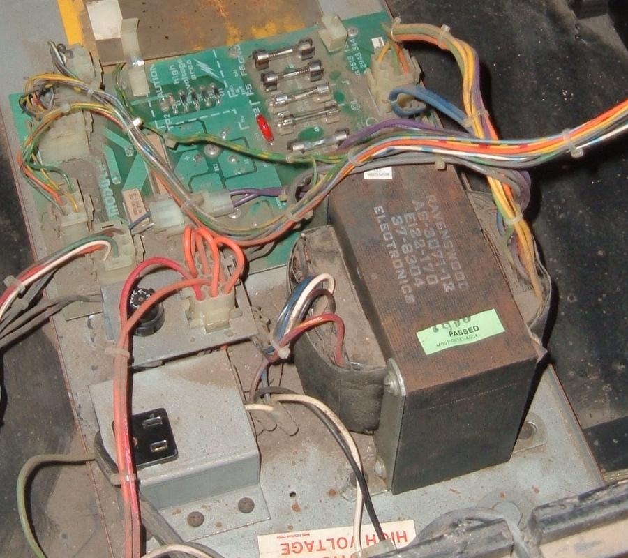
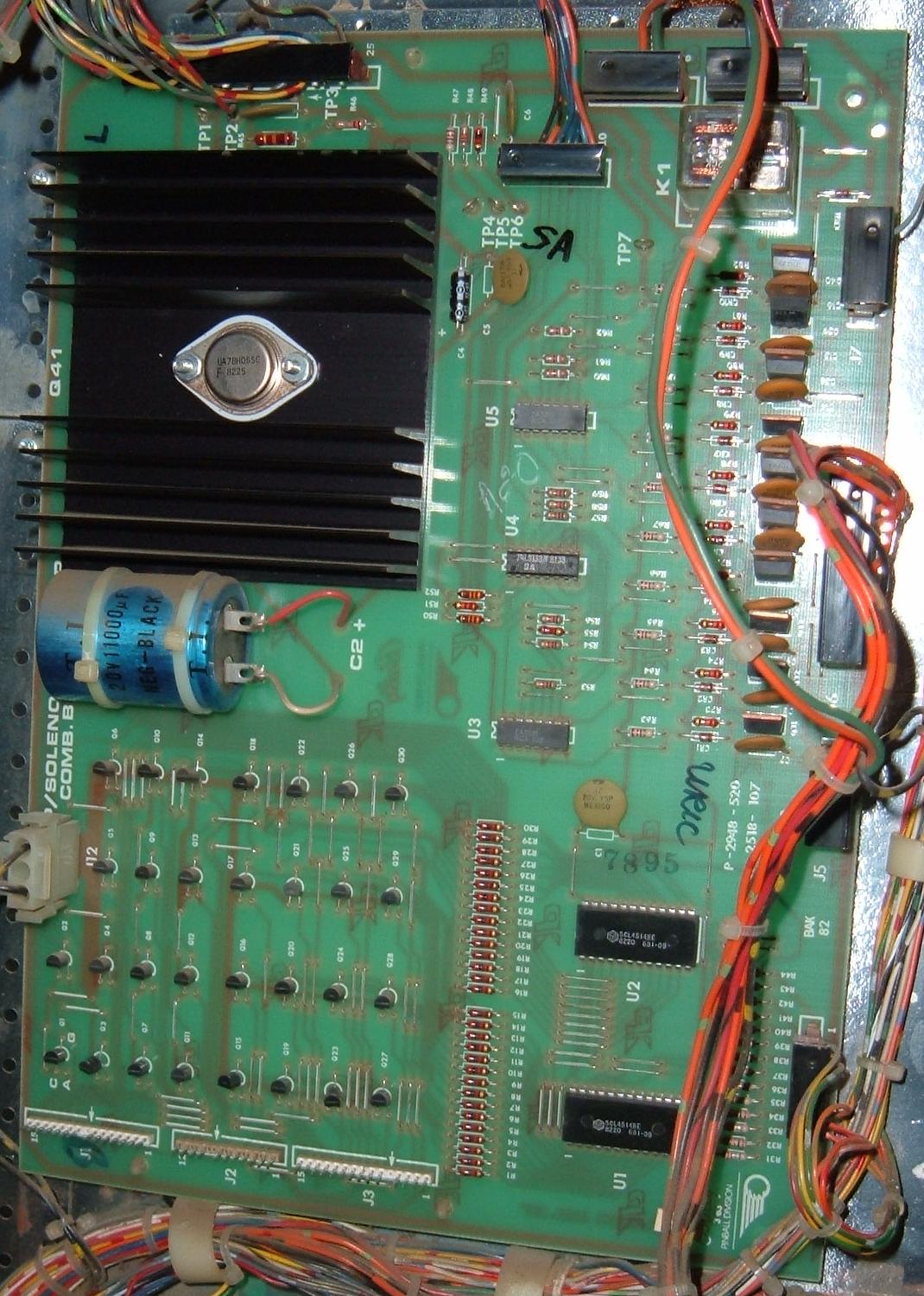
Baby Pacman Rectifier and Lamp/Solenoid Driver boards.
The power supply is a AS-2518-132 rectifier board.
It holds the game fuses and is generally pretty robust and
doesn't fail much. Unfortunately this board is different than the
AS-2518-54 rectifier board used on Bally pinballs from Xenon to Cybernaut,
but operates in the same manner. If you are familiar with the pinball -54
rectifier, you will feel right at home with the Baby Pacman -132 board.
The AS-2518-107 lamp/solenoid driver board often has problems. Most often the 2N5060 SCRs fail causing non-working or locked-on pinball playfield lamps. The 4514 lamp decoders (U1,U2) usually don't fail though. So if some playfield lamps don't work (and its not the bulb or lamp socket), suspect a 2N5060 SCR on the lamp/solenoid driver board connector. Note the color of the wire going to the problem lamp socket. Then find this wire color on the lamp/solenoid driver board connector. Then trace the connector its corresponding 2N5060 SCR. The lower leg of the SCR can be grounded, and the playfield light should turn on. If it does the wiring from the SCR to the playfield lamp is good, and the 2N5060 SCR should be replaced.
Also the SE9302 transistors (TIP102 replaceable) and CA3081 pre-driver (U3,U5) chips can fail causing locked-on or non-working solenoids. The solenoid drivers are decoded by a 74LS138 chip at U4. Also on this board is the +5 volt voltage regulator at Q41 and a 11,000 mfd filter capacitor at C2. This supplies power to the -133 MPU board. Often the C2 filter capacitor needs to be replaced.
Here's a list of the TIP102 (SE9302) transistors on the solenoid driver board and what they control. Listed in physical order from top down.
- Q40 = K1 flipper enable relay
- Q39 = left side saucer kickout
- Q38 = right side saucer kickout
- Q37 = outhole
- Q36 = 5 bank drop target reset
- Q35 = #1 drop target release (left side)
- Q34 = unused (originally going to be drop target #2)
- Q33 = #3 drop target release (center)
- Q32 = unused (originally going to be drop target #4)
- Q31 = #5 drop target release (right side)
Baby Pac Playfield Switches.
The MPU board handles all the switches except for the
joystick up/down/right/left, which is done by the Vidiot board.
- Right flipper (mounted on EOS)
- n/a
- Game start 2p
- n/a
- Rebounds (2)
- Game start 1p
- Right spinner
- Left spinner
- Coin II (right)
- Coin I (left)
- n/a
- n/a
- n/a
- n/a
- Tilt (2)
- Slam
- Top Right loop lane
- n/a
- n/a
- Top Left loop lane
- Tunnel outlane
- Fruit outlane
- Right inlane
- Left inlane
- #5 drop target (right)
- #4 drop target
- #3 drop target (center)
- #2 drop target
- #1 drop target (left)
- Outhole
- Right kickout
- Left kickout
Baby Pacman Vidiot Board LED Flashes.
The Vidiot board also has an on-board LED that flashes ten times at power-on.
The sequence of these flashes can be confusing. The first three flashes
come fairly slow, with the first flash coming about one second after
power-on, and flashes 2,3 about one second apart. Flashes 4,5,6 are much faster
and close together. And flashes 7,8,9 are very fast and very close together,
making them hard to count. Then there's a two second pause, and
the 10th flash is seen.
Here is an explanation of the Vidiot board LED flashes.
-
1st Flash.
After the 6803 CPU chip at U27 resets properly (using a 100 millisecond wait for the 5 volts to stablize), the sound 6803 CPU chip (U27) attempts to test the 2764 sound EPROM at U29. If the chksum from the U29 sound EPROM is good, the first flash is shown. If there is no first LED flash, usually the sound EPROM at U29 is bad.
2nd Flash.
Next the sound 6803 CPU chip at U27 attempts
to test itself and its onboard RAM by writing and reading a pattern
to its internal RAM. If this RAM write/read is sucessful,
the second LED flash is shown. If there is no second LED flash, usually
the sound CPU chip 6803 at U27 is bad.
The Vidiot Sound section test is now complete. The rest of the LED flashes pertain to the video game portion of the Vidiot board.
3rd Flash.
After a pause, the 6809 CPU chip at U8 attempts to test the program EPROM at U12.
This is done using a chksum routine. If the chksum is correct, the third
LED flash is shown. If there is no third LED flash, the EPROM at U12 is bad
(or its socket or a trace is broken going to U12).
4th Flash.
The 6809 CPU chip at U8 attempts to test the program EPROM at U11,
in the same manner as U12 was tested. If the chksum for U11 is good,
the fourth LED flash is shown.
If there is no fourth LED flash, the EPROM at U11 is bad.
5th Flash.
The 6809 CPU chip at U8 attempts to test the program EPROM at U10,
in the same manner as U12,U11 were tested, using a chksum.
If the chksum for U10 is good, the fifth LED flash is shown.
If there is no fifth LED flash, the EPROM at U10 is bad.
6th Flash.
The 6809 CPU chip at U8 attempts to test the program EPROM at U9,
in the same manner as U12,U11,U10 were tested, using a chksum.
If the chksum for U9 is good, the sixth LED flash is shown.
If there is no sixth LED flash, the EPROM at U9 is bad.
7th Flash.
The 6809 CPU chip at U8 attempts to test the scratch RAM at U13,U14 (2114).
This is done by writing a memory pattern to U13,U14 and then reading it back.
If the pattern is read correctly, the seventh LED flash is shown.
If there is no seventh LED flash, the RAM at U13 and/or U14 is bad.
8th Flash.
The 6809 CPU chip at U8 attempts to test the PIA chip (6821) at U7.
If the PIA is good, the eighth LED flash is shown.
If there is no eighth LED flash, the PIA at U7 is bad.
9th Flash.
The 6809 CPU chip at U8 attempts to test the VDP (Video Display Processor, which
is the TMS9928 at U16).
If there is no ninth LED flash, the TMS9928 at U16 is bad.
10th Flash.
The 6809 CPU chip at U8 attempts to test the VRAM (Video RAM, the dynamic screen memory),
which is the eight RAM chips at U19 to U26 (MCM4517 or 8118-12).
The 6809 tells the VDP (Video Display Processor, TMS9928 at U16)
to dynamically refresh the VRAM.
If there is no tenth LED flash, one ore more RAM at U19 to U26 are bad.
Remember there is a slight pause before the tenth flash is shown.
Granny and the Gators.
Granny uses the updated "Vidiot Deluxe" board instead of the
Baby Pacman "Vidiot" board. The concept and boot up process/handshaking
are essentially the same. But since the Vidiot Deluxe board has an
addition TMS9928 proccess, more RAM and more ROM, the boot LED flash
codes are different.
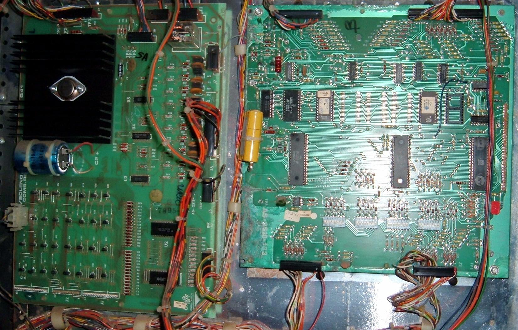
The boards inside a Granny and the Gators. Notice they are
mounted inside the game, not on the back door (like a Baby Pacman.)
Granny and the Gators also uses a Bally "Cheap Squeek" sound board. Because of this, the first two LED flashes on the Vidiot board reflect this usage. In a normal working Granny and the Gators there are a total of 14 LED boot up flashes. But if you are booting a Vidiot Deluxe board on the work bench without the Cheap Squeek board, the Vidiot boot up LED squence starts at flash #3.
The ROM code for Granny and the Gators' MPU and Vidiot and cheap squeak boards is available here.
Granny and the Gators (and Baby Pac) MPU on the bench.
Again G&G uses a -133 Bally MPU board, like Baby Pac. This means instead of 43 volts DC,
it uses 6 volts GI power for the lamp strobing process at connector J4 pin 15.
Be aware of this if you are booting in a test
fixture. And yes you can boot the G&G MPU board in a test fixture. Since
there's no communications with a Vidiot board, the board does act a
bit differently. That is, upon boot, the Granny MPU goes into a kind of
Lamp test. At least that's the way it appears. Actually it's flashing
both the A and B lamp sides, but only shows one of the two lamp sides.
Without communications with the vidiot board, this is normal behavior.
If there was a vidiot deluxe board attached, the normal attract lamp
mode would work. Note this is unlike a Baby Pacman -133 MPU, which goes into a "normal"
attract mode on the test fixture (without the vidiot board attached.)
After either G&G or Baby Pacman is booted on the test fixture, press the "test" button once, and the MPU will seemingly go "dead". But what it's actually doing is showing the communications screen (which you obviously can't see with regular pinball score displays!) Press "test" one more times, and the -133 goes to lamp test. On a regular Bally test fixture, all 40 controlled lamps will flash off and on (but at a slightly different speed compared to a -35 board.) Press "test" one more time, and the coil test will start. For Granny and the Gators, there's only four coils (and the flipper relay).
A common failure point for the Vidiot boards is the TMS9928 chip. Baby Pac uses one, Granny & Gators uses two of these. On Granny, if the game seemingly boots with all it's LED flashes (both MPU and Vidiot), yet the game screen is blank and a few playfield lights are flashing on and off, this is probably a bad TMS9928 chip.
On Granny and the Gators' -133 MPU flicker and six LED flashes, note that flash number two (the 5101 RAM test) is longer coming that say a normal -35 board. Don't be alarmed by this, it is normal.
Vidiot Deluxe board as used in Granny and the Gators.
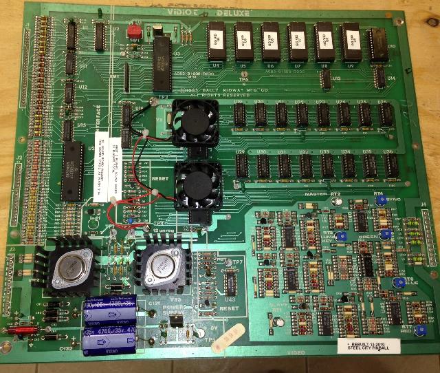
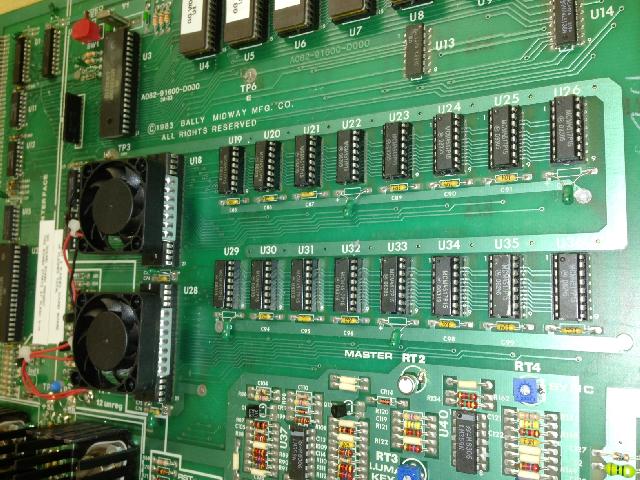
Vidiot Deluxe board's RAM and two TMS9928 (with added heat sink/fan).
Granny and Gators' Vidiot Deluxe LED Codes.
Because of the additional TMS9928 chip and added RAM/ROM on the
G&G Vidiot Deluxe, the LED boot up sequence is different. Note the LED
flashes come very quickly are are not easy to count. Here's the
codes. (A flash means that "check" is completely.)
- U3 Cheap Squeek sound board check
- U1 Cheap Squeek sound board check
- U9 Vidiot Deluxe check
- U8 Vidiot Deluxe check
- U7 Vidiot Deluxe check
- U6 Vidiot Deluxe check
- U5 Vidiot Deluxe check
- U4 Vidiot Deluxe check
- U10 Vidiot Deluxe check
- U27 PIA Vidiot Deluxe check
- U18 Master VDP check
- U19 to U26 RAM check
- U28 Slave VDP check
- U29 to U36 slave VRAM check