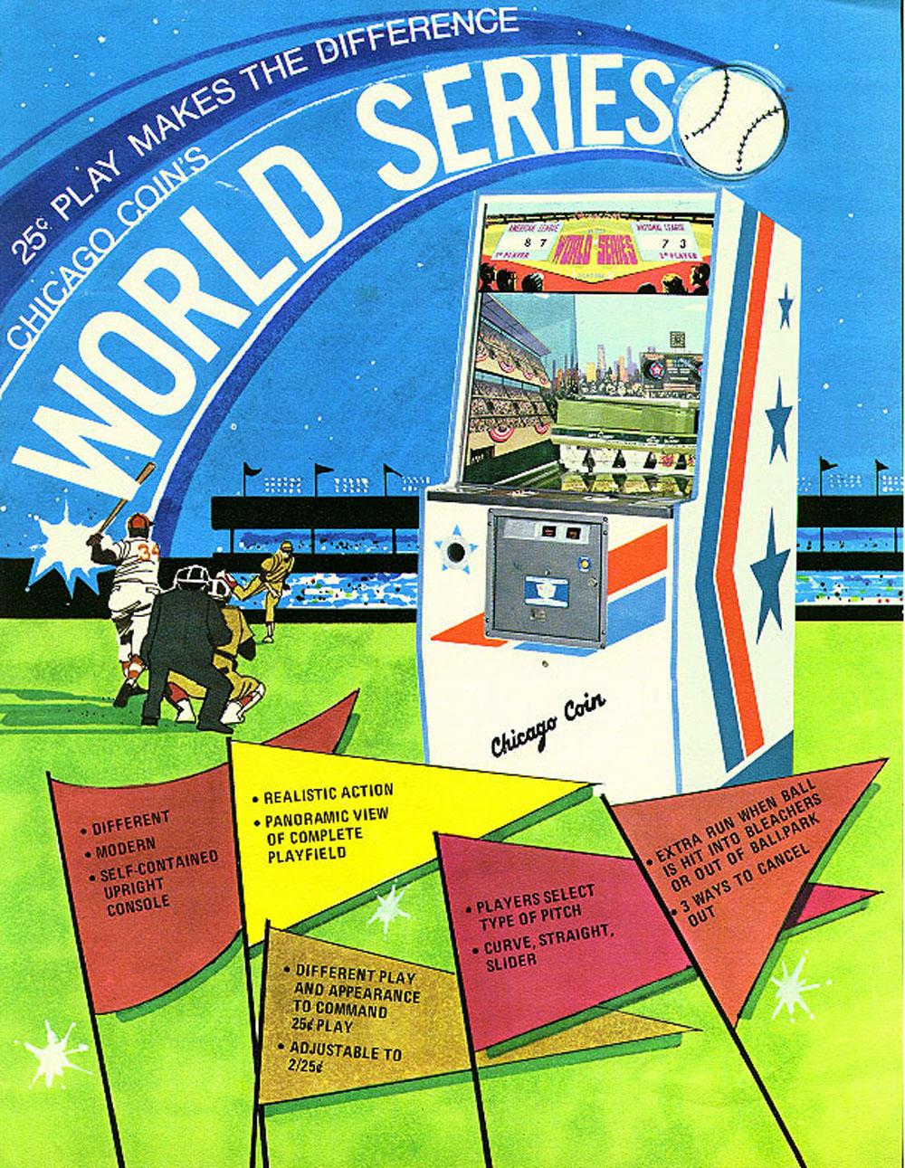
Description: World Series, Chicago Coin, 1974, two player, baseball pitch and bat in a video game style cabinet, also known as "Deluxe World Series", though CCM refers to the game on the schematics as "World Series", without the "Deluxe" (the backglass has the Deluxe printed.) Uses the standard CCM (and Midway) sized balls 13/16" (.8125"). Electronic sound of a cheering crowd when a hit or home run is made (two sounds, low cheer and high cheer with whistle for home run.) If an out is made, the chime coil is rung. A knocker coil is used when ever the bat swing button is pressed (for a bat type sound.) If a super home run is hit, it can cancel one out (operator selectable.) Has three pitches using magnets under the playfield (curve, slider, fastball.) The World Series is basically the same game as the 1973 CCM Baseball Champ.
1974 CCM World Series Schematics.
One problem I often see with this game is the sound board is often missing.
It's an edge connector single board, mounted on the lower front right side
of the bottom relay/motor panel. For whatever reason, this board goes missing or
is damaged. But there's a solution. You can replace this board with
an inexpensive MP3/Wav player like the
Electronics123.com FN-BC04
four button sound board. At about $20 it's a good solution. This board uses a MicroSD card,
but it also has 4meg of onboard RAM (no need to use a MicroSD card.) You can used a
USB cable to hook the board directly to your computer, and the board acts like a remote
RAM drive. Then you can copy sound files to the board. There's also a Read.Cfg file
that needs to be set to "2" (the default is "0"). This makes the sound plays non-interruptable,
which is needed for this game (otherwise the home run sound will be truncated.)
I have sound files (all about 4 seconds long) which you can download and put on this sound board.
Note the sound files need to be 3 or 4 seconds maximum length to match the original sound board's functions:
As for the wiring, the game has a 10vac output used for the original sound board.
Using a bridge rectifier and a 2200mfd (or higher) cap and a 1amp fuse, this can be used to
power the Electroncs123 sound board. Note you'll have to change the AC stock 1/4 amp
fuse to 1amp, as the Electronics123 board needs more power (it has a 15watt sound amp.)
I also buy the $1 sound board test buttons and solder them to the sound board.
This way you can test the board without actually starting a game. In the picture below
you can see where I added an additional fourth NO switch to the top of the Out relay (purple and white wires),
which triggers the Out sound on the new sound board.
Here's the edge connector pinout from the original CCM sound board connector
to the Electronics123 FN-BC04 four input sound board solder pads. I used a
Molex .062" nine round pin connector, so the sound board could easily be
removed (for sound changes or other maintenance.) Note pin1 of
the original CCM sound connector is closest to the front of the game. I leave
the original sound board connector in place, just in case a stock sound board is
found in the future. But here's the wiring from the original CCM sound board connector
to the new Electronics123 sound board:
1974 CCM World Series Instructions/Parts manual.