1a. Before Beginning: Introduction to Pinball Repair
-
Before attempting any pinball repair, there are some basic
questions that should be asked. Simple things like, "how
is the playfield glass removed?" or
"how is the backglass removed?" (if you're asking these questions,
even this basic document is probably beyond your skill set, and I recommend
hiring a professional to fix your games).
- Screwdrivers: two phillips (#1 and #2), two flat head (one small, one medium).
- Nut drivers: full SAE set (english units).
- Wrenches: full SAE set.
- Allen wrenches: full SAE set.
- A good shop light.
- Flexstone (EM games only) for cleaning switch contacts.
- Contact adjust tool (EM games only) for adjusting switch contacts.
But a very simple thing that is often asked is, "what equipment is needed to fix a pinball?" This document covers the electronic equipment needed, and how to use it. And the other repair guides cover the basic non-electronic tools needed for each system of games. But for completeness (since we mention all the electronic equipment needed below), here are some basic non-electronic tools need for pinball repair.
Beyond the basic tools, a level of "common sense" is also needed when fixing games. Remember the people that designed these games were probably much smarter than you and I, so we need to trust their design (unless I tell you otherwise, ha!) If they have a connector on a board, and it is burnt, it's best to replace it (and not solder wires directly to the board, circumventing the connector, and making the game "unservicable" in the future!)
As my buddy Kirb says, "Now let's start with some basics. Do you know what an amp or volt is? Do you know that electricity can kill you? Are you scared to look under the playfield of your game when it is turned on? Think about all of this before trying to save $100 and fixing a game yourself. For those of us dumb enough (like me) to waste time working games, we should all first learn how to do so." Hopefully this document (and some common sense) should save a new pinball learner some trouble.
1b. Before Beginning: Should you attempt Printed Circuit Board (PCB) repair?
-
Soldering coils and switches is one thing. But fixing printed
circuit boards is a whole other thing!
Before attempting any Printed Circuit Board (PCB) repair, ask
yourself some questions (soldering pinball coils is one thing,
but replacing a soldered-in chip on a circuit board is another):
- Do you have any soldering experience?
- Do you have any PCB soldering experience?
- Do you have the proper tools for PCB soldering?
- Do you have the patience required to go "slow and careful"?
If the answer is "no" to ANY of these questions, STOP! Do not work on circuit boards! Send them out for repair to a professional. In the end, much more money will be saved having the boards fixed professionally, then attempting to repair them yourself.
Keep in mind some pinball circuit boards are not replaceable! So if a board is made "non-serviceable" (unusable), a lot more money can be lost than a professional repair would have cost in the first place. In some cases, it is possible to make a game "junk" if a non-replaceable circuit board is ruined.
This is the key point to this document. Do not think because all the procedures here look easy and anyone can do them! Do NOT become over confident. A "hack" repair can RUIN a circuit board. And most repair facilities will not fix circuit boards that have been unsuccessfully repaired ("hacked") by someone else.
1b. Before Beginning: How did you learn to solder?
-
Soldering a new coil in a game is one thing. A sloppy
job won't really affect much. Sloppy soldering on a
circuit board is another matter however. A circuit board can be totally ruined with
bad soldering. Also the equipment and techniques are a bit different
on circuit boards than on coils.
I remember when I first learned to solder. My dad taught me with a soldering pencil, some paper clips, and some rosin core solder. I was probably 10 years old, and I thought it was fun! What he had me do first was make a box out of the paper clips. Using needlenose pliers, I constructed one side of the three dimensional box. Then I soldered the points where the paper clips came together. When I was done, it was a pretty nifty 3-D box, and I was proud.
Nostalgia aside, this was a good first experience. It taught me how to solder, at the expense of only some paper clips. If one has novice soldering skills, start small and practice! Sacrifice some paper clips and make a "box".
1b. Before Beginning: Practice makes Perfect.
-
If a pinball machine is in the future plans, then the owner
needs to know how to solder! Knowing how to do basic soldering of
wires onto solenoids (coils) and switches is a must. Due to the
vibration of solenoids and players in a pinball machines,
wires do break off coils and switches. It happens, and the owner
will need to know how to deal with it!
Basic soldering is pretty straight forward. Get a soldering station and some good quality solder (as decribed below). Having the right tools is 75% of the job! And remember, a good solder job on a coil or switch starts with a good *mechanical* connection. That is, the wire should be mounted to the coil or switch lug before being soldered, and stay put! After that, soldering the wire is just a matter of heating the wire and the lug *together*, and then applying a small amount of solder. The solder should be applied to the wire or lug, and *not* directly to the soldering iron's tip. This ensures the solder will flow over the wire and the lug, and that they are heated to the right temperature. The soldering iron can then be removed from the joint. Now keep the solder joint steady while it cools, otherwise it could produced a "cold" solder joint (one that does not conduct electricity freely).
Once this basic soldering is mastered, the next step (maybe!) is solder on a Printed Circuit Board (PCB). If one has never soldered a PCB before, don't try your first attempt on a (expensive!) pinball CPU or Driver board! Practice on some junk boards first.
Junk circuit boards are easy to get. Video game collectors can often provide some junk JAMMA games board or other boards. Maybe there's an old PC computer (which you couldn't give away!) that's could be used. Practice circuit boards aren't that hard to find. You just gotta look. Even if one has to pay for some junk boards, it's well worth it.
Another alternative is to go to Radio Shack and buy some cheap resistors (about 50 cents for five), and some "breadboard" print circuit board material with holes, part number 276-150 at $1.19, or part number 276-168 at $2.49. Practice soldering the resistors to the board. This is not as good practice as using a real printed circuit board though (there's nothing like the real thing). Remember to clean the copper on the Radio Shack board with some Scotchbrite before trying to solder them (unsoldered virgin copper likes to oxidize, making soldering difficult). But please read the tips and info below before starting.
2a. Tools Needed: Good Lighting and Magnification.
-
Good circuit board repair work requires good light! Good
light is cheap. If there isn't good light in the workshop, go to
the hardware store and buy some 4 foot dual florescent lamp fixtures
(about $10). I personally like florescent light for repair work.
It's cheap (to buy and run), and it does a good job.
Florescent light is best because it is "whiter" than incandescent light.
|
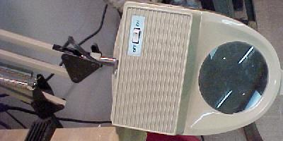
An incandescent version of the nifty magnifier lamp. |
|
-
Buy a good magnifier.
A good magnifier allows examination of circuit boards in great detail, to view repair work quality. There are two types of magnifiers available. One is worn on the head, and it requires an external light source. To focus, move your head to a certain distance from the viewing object. The other (more desirable in my opinion) magnifier is on an adjustable "arm", and has a built in light source. This is what I personally prefer, and I find it extremely useful for finding circuit board defects. MCM Electronics (800-543-4330) sells these, part number 21-935 for $49, but it's often on sale for $39. This is a nice version with a built in circular florescent lamp. There is also a cheaper version with a standard incandescent light bulb for about $29 (often on sale for $19), part number 22-3995, but the florescent lamped model is much nicer.
If one is absolutely cheap and broke, a Magna-Lite lighted magnifier reader is also available. This hand-held device works well too, and can fit in a pocket. It has a high intensity bulb with a switch. Available in 4x, part number 21-6595, for $6.99, from MCM Electronics.
2b. Tools Needed: Get a good Soldering Station.
-
When doing PCB repairs, it is important to buy the right tools!
Yes, this will cost money. There is NO way around that.
But do NOT buy cheap tools.
For example, a good soldering station can last a lifetime, and make
soldering SO much easier and better. Don't be cheap (unless
I suggest it!)
Buy a Good Soldering Station.
Your dad's old soldering gun isn't going to work for soldering circuit boards.
A GOOD soldering station is needed.
Melting metal in close proximity to delicate electronic components requires the right tool.
When working on printed circuit boards, a precise amount of heat is applied
for a short period of time to a very precise area. The best way
to do this is with a quality soldering station.
Expect to spend up to $50 to $150 for one.
Soldering stations are nice because they allow you the
soldering temperature to be exact. Also they are grounded nicely, to isolate
the iron from its power source (this protects static sensitive chips).
I personally like the Weller brand (USA made) soldering stations. Weller even makes a nice "budget" brand under the Weller Ungar name. If you are really on a budget, the Tenma brand (import) is decent too. I personally use a Weller station for my workbench, and use a Tenma for the garage. Which ever you get, buy some extra soldering tips! I prefer the "chisel" soldering tip shape (1/16" wide), opposed to the "cone" shape.
|
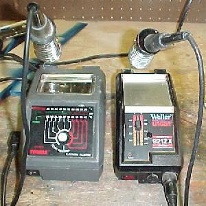
Left: Tenma #21-7930 with LED temperature display. This costs about $40 to $80. A great station for the price. Right: Weller/Ungar model 921ZX again with a LED temperature display. This costs about $90 to $120. |
|
-
Temperature Control is Important, not Wattage!
The important thing to get in a soldering station is temperature control, and not some goofy variable rate that has no reference point (like "1 to 10"). An actual temperature range is important. Soldering is best done at 600 to 700 degrees (personally I usually solder at about 650 or 700 degrees), but a decent soldering station is usually adjustable from 300 to 900 degrees. A soldering station that doesn't provide a temperature guage is probably varying the wattage, and not the temperature. This is far less useful.
For cheap soldering irons, the wattage of the iron is a measure of the power that is used to heat the iron. So a 25 watt soldering iron is always running at that level of power consumption (like a 25 watt light bulb would), and is ALWAYS generating heat. The soldering iron's tip absorbs the heat. As long as power is supplied the tip will continue to get hotter until it reaches "equilibrium" (the maximum temperature where heat will be conducted to the air at the same rate heat is applied to the tip). As soon as a soldering iron's tip makes contact with metal, heat will transfer from the tip quickly. The higher the wattage iron, the quicker the tip will heat up again. When a cheap soldering iron is idle, it is MUCH HOTTER than it needs to be for soldering. But the moment you place it on metal for soldering, it cools down. For this reason, if not using a cheap soldering iron for more than 5 minutes, turn it off. Otherwise it will get too hot and ruin the iron's tip (at minimum), or apply too much heat to the solder joint (at worse).
The above is why cheap soldering irons are bad; there is no way to control the actual temperature of the iron! That's why a good soldering station is really a must. The right temperature can be dialed in. Then the station will monitor itself, turning power to the station's soldering tip on and off as needed to maintain the desired temperature. Good soldering stations also provide a level of isolation so static sensitive chips won't be easily ruined by the soldering iron.
Tenma's soldering station with LED temperature display #21-7930 (formerly #21-147) is available from MCM Electronics (800-543-4330) for $75 ($40 on sale). Tenma also has a digital display version of this station for $100 (often on sale for $60) #21-7935. Also get some replacement soldering tips, screwdriver "chisel" style #21-7983 (formerly #21-927, 3/64" wide chisel tip for circuit board work) and #21-926 (1/6" wide chisel tip for bigger jobs like coils) for $2.49 each. Then even sell a complete replacement grounded iron (with tip) for these two station #21-7936 (formerly #21-151) for $10.
Finally Weller's WES50 soldering station is also available from MCM for about $110 (often on sale for $100). This model has adjustable temperature range from 350 to 850 degrees (though the scaling is strange). The Weller brand will cost a bit more, but is probably worth the extra money.
I'm Poor; Must I Spend $70 on a Soldering Station?
If you want to do circuit board work, YES!
(But wait for MCM Electronics to have a sale and get the Tenma #21-7930.)
If one doesn't have the money for a decent
soldering station, a low-wattage (25 watt) soldering
iron can work. Don't go higher than 25 watts though.
Home Depot sell a decent orange Weller SP23
soldering iron for about $15, which works OK too. It is rated at 25 watts
and 700 degrees (though that temperature is not fixed). The Weller SP23 works
great for playfield coils on EM and Solidstate games, and "light" circuit
board work. But remember the warning
above; for soldering printed circuit boards, you really need a temperature
controlled soldering station!
2c. Tools Needed: Get good solder!
-
Using good solder is VERY important in circuit board
repair. The best solder is made by Kester (USA made).
Radio Shack solder is Kester solder (but with the Radio
Shack label). Here are the solder specs you need:
- Rosin flux core. No other core will suffice!
- 60% tin, 40% lead (60/40) formula.
- .032 inch diameter for circuit boards (.040 inch or larger for coils if desired).
Rosin core flux is very important. Any other type of flux will not work for circuit board repair. For example, acid flux is designed for plumbing work, not electronics! Most hardware stores only sell 95/5 lead free solder, which won't work for circuit board repair. Radio Shack's solder is made by Kester, and is quite good.
Solder diameter is also important. Anything bigger than .032" is usually too big, and will put too much solder on the circuit board. I use .032" for everything, including coils and fine circuit board work. Some people like to have the larger .040" or .062" solder around for soldering wires to coils, and other larger soldering jobs. But personally I don't see the need for it.
2d. Tools Needed: DeSoldering Tools.
-
When doing circuit board repair, a method of
desoldering old parts is also needed. When pricing desoldering
tools, make sure to also price new tips! (Obviously this does
not apply to desolder braid). Often the price of a new tip can
be very expensive. And a new tip will be needed at some point.
It really is a good idea to buy an extra tip or two when purchasing
a desoldering tool.
Replacement tips come in a variety of hole sizes. The "standard" hole diameter is about .040". This size will work for most pinball desoldering applications. Personally I tend to go .050" or even .060", as desoldering .156" Molex male header pins are usually too big for a .040" tip.
Desolder Braid.
Desoldering braid is a very common and cheap desoldering tool.
Available from Radio Shack, part number 64-2090, for $2.29.
Desoldering braid is just flexible copper braid, about 1/4" wide.
Just put the braid over the joint you are desoldering, then
put your hot soldering iron's tip over the braid. As the braid heats
up, it will "absorb" (wick) the melted solder from the joint. When you're done
with that joint, move down the braid to a fresh spot (you can *not* reuse the same
area of the braid again).
The downside to solder braid is heat. Usually it takes more heat to unsolder using braid. Also it's not very fast. If doing a lot of unsoldering, it will take some time and lots of patience. It works OK with large holes to desolder. But when desoldering say a chip with small leg holes in the circuit board, I find the braid difficult to use. I personally don't recommend it or use it, but it does work in a pinch, and it's inexpensive.
|
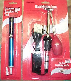
Left: the Radio Shack vacuum desoldering pump, known as the mini "Soldapullt". I use one all the time! It works great and it's inexpensive. Right: the Radio Shack desoldering iron, and an extra "iron clad" tip. |
|
-
The Radio Shack Desoldering Iron.
For the average hobbyist, this is an usable desoldering tool. The Radio Shack desoldering iron is part number 64-2060, $9.99. It is simply a 45 watt soldering iron with a hollow tip, and a red suction bulb. After letting this iron warm up for about 15 minutes, compress and hold the red bulb. Then put the hollow tip over the joint to desolder. After the solder has melted (a couple seconds), release the red bulb, and the solder will be sucked from the joint (this theory is how expensive desoldering stations work). An easy one handed operation that requires minimal practice.
But this style of desoldering tool comes with the same warning as non-adjustable temperature soldering irons; the amount of heat applied can *not* be adjusted! Because of this, the Radio Shack desoldering iron can be dangerous. Too much heat, and the traces and solder pads can delaminate from the circuit board! Just keep this in mind. Remember, it is a 45 watt desoldering iron, so it generates *lots* of heat. With a little practice, the Radio Shack desoldering iron can work well. It's hard to beat for the price, and I personally find it easier to use than most other low-cost desoldering tools. But too much heat can be applied with this tool, making it dangerous for the "newbie". Because of this, I would not recommend this tool for first time users unless they practice a lot on junk board first.
Also make sure to buy extra tips for this desoldering tool. They sell two styles of tips; get the "iron clad" version, which costs about 70 cents more, part number 64-2062, $1.99 (the iron clad version will last much longer than the standard version). A clogged or enlarged tip on this tool will render it useless.
Desoldering Vacuum Pumps (Soldapullt); Newbie Recommended!
A very common desoldering tool is known as the "Soldapullt". It's
a large syringe type desoldering device with a Teflon tip (get a replacement
Teflon tip when buying this tool).
Lots of technicians use this desoldering pump because it's
cheap and works well. The downside to this tool is
it requires TWO hands (one to hold your soldering iron, and
the other to hold the Soldapullt).
You are better off getting the bigger Soldapullt III, but Radio Shack also
sells a mini blue Soldapullt version (part number 64-2098, $7.99) that works well.
The larger Soldapullt III comes in normal (blue) and anti-static (silver)
versions. The anti-static version would be preferred.
MCM also sells an low-static Soldapullt, part number 21-4700, for $9.99.
Personally I use the blue Radio Shack version all the time and find
it to work great! When it breaks I throw it away and buy another.
I use it on all kinds of things from delicate circuit boards to
removing solder from coil lugs.
The biggest advantage to a Soldapullt tool is a soldering station can be used to heat the joint being desoldering. This means the desoldering temperature can be controlled via the soldering station. This is probably the single biggest advantage to using the Soldapullt desoldering tool (aside from price). Because of this, I highly recommend the Soldapullt tool for first time "newbie" repair people. But remember, practice is necessary to use it! So find some junk boards and try it out (instructions on how to use this tool are below).
Better (more expensive!) Desoldering Irons.
If the money is available, or one is doing lots of desoldering,
a "real" desoldering station should be purchased. These
consist of a small suction pump, connected to a soldering
iron with a hollow tip. They work much like the Radio Shack
desoldering iron, except there is an electric air pump instead
of a manual suction bulb, and the soldering tip is temperature controlled.
These desoldering station will use the least amount of heat, and do the best job desoldering.
Also available are desoldering stations that uses compressed
air instead of a dedicated electric air pump. These work the best
(since the air source can be a larger 100 psi air compressor),
but are obviously not as portable.
I can't stress how much better these units are than the previously discussed and less expensive desoldering tools. If working on any games that require a fair amount of desoldering, these tools will make the job FAR easier, faster, and less problematic.
|
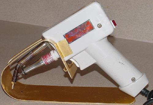
The XYtronic "One Shot" #2008 for about $99. I can not stress how good this desoldering tool really is, especially for the price! I use it "on the road" as a small and convenient desoldering tool, and it works great. |
|
-
Hakko sells a nice
desoldering iron model 808 for about $175. It has a self-contained vacuum pump, and
is about the size of the soldering gun. This is a great desoldering
tool for the price. I personally use this tool as a "on the road"
portable desolder station, and I am amazed how well it works. Temperature
is adjustable via a small pot, but it's more designed to be set once
and not constantly readjusted. For the price this is a great
desoldering tool. Takes about 5 minutes to warm up and is ready go.
Just put the tip over a solder pad, wait a second for it to melt
the solder, then pull the trigger. When finished and the tool cools,
remove the spring loaded solder collector tube and clean out the old solder.
That's about all there is to it. I have been using this tool for several
years and it works great. Just make sure it warms up for 5 minutes
before using or the suction tube will clog.
|
The Tenma desoldering station. Note the temperature LED. |

|
-
Tenma also makes a nice desoldering station, model 72-6340, for about $299 ($250
on sale) at MCM Electronics (800-543-4330).
It has adjustable digital temperature from 410 to 900 degrees. It is a self
contained station with its own compressor.
Other Desolder Parts to Buy.
No matter what desoldering tool is purchased, make sure to get some
extra tips. Again I would recommend .040" hole diameter, or even .050".
Also all desoldering stations also use some sort of filter to keep the old solder from getting into the air source (this filter is usually located in the solder collection tube). The filter could be as simple as a (100%) cotton ball (do NOT use synthetic cotton, as it will melt!) Have some spare filters around, and be prepared to replace this filter every now and then. Another replacement item is the rubber gasket that seals the solder collection tube to the "Y" adaptor. With time these dry out and fall apart. So it's not a bad idea to have a few of these rubber gaskets around too.
Finally, many desoldering stations also offer a declogging "toolkit" that includes a set of miniature round files. These are used to clear the desoldering tip and adjacent "Y" adaptor of any stuck solder. It's a good idea to have one of these toolkits too, if it didn't come with the new desoldering station.
Buying a Used Desoldering Station (Ebay).
Often good quality desoldering stations can be found on Ebay.
Just be careful when buying in this environment. Almost
guarenteed the station will need a new tip, a new filter, and
a new solder collection tube gasket, and that the original
declogging "toolkit" is missing. Sometimes the heater
element or compressor can be bad too! So ask questions and check out the
price of new tips and other parts. Also remember, a used
desoldering station is usually being sold for a reason (it doesn't
work well any more!) But good deals can be found because many
people don't realize that the tip and collection tube gaskets
do wear out and need to be replaced every now and then, and that
the "Y" adaptor can clog! (especially if the desoldering station
was used before it was hot).
What Ever You Use, PRACTICE!
Desoldering is an art, and practice is needed to get good at it. Get some junk
circuit boards, and remove some components from them. That
way you won't be experimenting on "real" boards. Also see the section below on
desoldering tips.
2e. Tools Needed: DMM (Digital Multi Meter).
-
"What is a DMM?", you ask. DMM stands for Digital Multi Meter.
It is THE tool you will use the most when repairing electronic
pinball games. This tool is used more than any other in pinball
repair (other than a soldering iron!) DMM's do lots of good things:
- Test for "continuity" (if two things are directly connected).
- Measure voltage.
- Measure resistors.
- Test diodes
- Test transistors.
- Measure capacitance (on some DMM's)
- Continuity beeper ("buzz tone").
- Diode test.
- Capacitance test (up to 20,000 mfd, anything less is far less useful).
- Transistor test.
- Logic probe.
- True RMS (good for very accurate AC voltage measurements only).
- RS-232 communication (for your computer).
- Temperature measure.
An electronic pinball game repair should not even be attempted without a decent DMM. It's probably the single most valuable tool. The best name in DMM's is probably Fluke. But for pinball repair purposes, any decent brand will probably work fine.
DMM Features.
For the most part, "more is better" when it comes to DMM's.
All meters will test voltage (AC and DC), and resistance (ohms).
Here are some other options to consider.
Strongly Suggested:
Optional, but nice to have:
Not Needed:
|
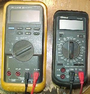
Left: Fluke 83 auto ranging DMM. Notice the simple dial selector and the yellow rubber shock case. This meter costs about $250. Right: Tenma 72-4025 DMM. This is NOT an auto ranging meter (specs here). Notice the dial selector has A LOT more settings! This meter costs about $70, and came with the gray rubber shock case. This is a great meter, as it does everything, and is priced very nice. |
|
-
Auto Ranging?
Auto ranging meters are great for beginners. Manual ranging meters require the user to know something about the part they are testing. For example, if testing a 1 meg ohm resistor, but the meter is set to the 10k ohm range, the resistor will show as "open" (null resistance). The meter needs to be set to a higher resistance range for this test. This means the resistor or schematic needs to be examined before testing it, to figure out what its value *should* be (based on the schematics or the resistor's band colors), Then the DMM is set accordingly.
In the case of an auto ranging meter, it does an initial test on the resistor, and figures out the correct range. All the user needs to do is to set the meter to "resistance", and it figures out the rest.
What are the Disadvantages to Auto Ranging DMM's?
Auto rangers aren't for everyone, as they have some disadvantages.
First is cost. An auto ranging DMM will cost more. Second
is speed. It takes a moment longer to test a component on an autoranging
DMM. This extra time means nothing, *unless* using the meter
to measure a "pulsing" value. For example, a voltage that goes up
and down over a short period of time. An auto ranging DMM won't be
fast enough to read the voltage, set it's range, then read the voltage
again and display it. A manual range DMM would work much better here.
For this reason, most "seasoned" repair people do not want an
auto ranging DMM
(note many good auto ranging DMM's have the ability to turn the
auto range option off, and set the range to test manually).
DMM Leads and Clips.
Some DMM's come with threaded probe ends on the red and black
wire leads. These allow aligator clips to be screwed to the ends,
or other nifty attachment clips, to make using a DMM easier.
I highly suggest this type of leads. If your meter doesn't
have the threaded probe ends, at minimum get some
24" mini alligator clips (Radio Shack #278-1157, $3.99) or 30" alligator
clips (Radio Shack #278-001, $3.69) that can be clipped
onto the probes of the DMM.
Cheap DMM's are No Bargain.
Trust me, I've been there. Buy a decent meter! Cheap ones
break easily, and can give suspicious readings. Having
a nice DMM is something will be appreciated. For $60 or
more, a pretty nice meter can be bought. I find that if
the meter has a rubber "shock case" option,
buy it (if it doesn't come with the meter). Also the meters
that have an available "shock case" seem to be the better
(more durable) models (the ones without shock cases tend
to be "disposable").
2f. Tools Needed: Logic Probe.
-
"What is a logic probe?", you ask? Basically, a logic probe is a
small, cheap device that shows a circuit is either at zero or +5 volts.
Yes, some DMMs can do this too, but if the circuit
is running at any speed, the DMM (manual range or not) can not keep up.
The logic probe's job is to show these voltages, and the pulsing relationship
between them.
To understand why these "pulses" are important, some basic computer hardware concepts need to be understood. Simply put, a electronic pinball game is a computer. Computers (at a low level) can only deal with zeros and ones. A "zero" is basically zero volts DC (.8 volts or less). A "one" is basically +5 volts DC (2.4 volts or greater). The relationship between these two signals (voltages) is important. How fast or often a circuit goes from zero to +5 volts can determine how a circuit works. A logic probe can show if a particular pin on a chip is low (zero volts), high (+5 volts), or pulsing. The pulses can be "low pulses" or "high pulses" too. The logic probe shows this with three LED's, and sometimes a buzz tone too.
Unfortunately, a logic probe only indicates state changes (a zero or a one, which is 0 volts to .8 volts, or 2.4 volts to +5 volts, respectively). It is up to you to know if these are the expected changes!
Are All Logic Probes the Same?
Basically speaking, "yes".
Most logic probes will
have three LED's (low, high, pulse), and a switch (CMOS/TTL
select). Some logic probes are faster than others. For pinball, get one
that can test up to 5 mHz (or faster), but most can do that. Also
some probes emit a tone in addition to the LED's, which is a nice feature.
Radio Shack used to sell a decent logic probe at for $17.99, part number 22-303, but apparently Radio Shack is discontinuing these. MCM Electronics (http://www.mcminone.com) also sells a nice Tenma logic probe with memory, part number 72-190, for less than $25.
|
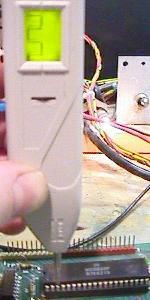
The Wittig Technologies osziFOX probe in action. |
|
-
The Best Logic Probe.
By far my favorite logic probe is made by Wittig Technologies (wittig-technologies.com). It's called the osziFOX Probescope, and it's a "probe style oscilloscope". It is a 5mHz (DC band width, other specifications available here) logic probe with a small LCD display screen, which draws a picture of the signal. It can even be interfaced it a computer through the serial port (giving a larger, more oscilloscope usage), or to a Palm Pilot IIIc! It runs on 9 to 13 volts DC (much like a regular logic probe). A pretty neat device, available from Test Equipment Depot (1-800-517-8431) for $ 69.00, or directly from the manufacturer at wittig-technologies.com. It gives a nice picture of what the signal pulses look like. Though I still recommend having a "regular" logic probe, this device is really cool and more like an oscilloscope. For someone just starting out in repair, this device really helps "see" what signals should look like. I personally find the "picture" which this probe draws as very useful (though it is no substitute for a real oscilloscope, which shows a picture of the signal in a time relationship).
2g. Tools Needed: Hand Crimpers.
-
Though a good set of hand crimpers is not an electronic evaluation or
measuring tool, it is needed for nearly all pinball repair. A hand crimper allows
the easy and precise replacement of Molex connector pins, which are
used extensively in pinball machines. Also needed will be connector
pin extractors, for cleanly removing connector pins from their housing.
|
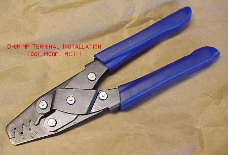
The BCT-1 hand crimper for crimping Molex connector pins. Picture by aeroelectric.com |
|
-
Here are the minimum connector tools required:
- Terminal Pin Hand crimper. These are used for all the different styles of Molex terminal pins. Aeroelectric's terminal tool BCT-1, available from aeroelectric.com/Catalog/tools/tools.html (about $32, good for all pin sizes) is an excellent crimper, or Molex crimper #63811-1000 (inexpensive but versatile, type 6), or Molex crimper #11-01-0015 (excellent but more expensive, type 3), or Waldom/Molex crimper WHT-1921 (good yet inexpensive, for .100"/.062" and .156"/.093" pins), or Waldom/Molex crimper WHT-1919 (really for .156"/.093" pins only), or Amp 725 (probably no longer available), or even Radio Shack #64-410 (last resort, not very good and not recommended).
- .093" Round Pin Extractor: Molex part number 11-03-0006, or Waldom/Molex part number WHT-2038, or Radio Shacks part number 274-223 (in this case the Radio Shack tool is pretty good).
- .062" Round Pin Extractor: Molex part number 11-03-0002, or Waldom/Molex #WHT-2285. Optional, as this size is not used nearly as much as the .093" size.
- .156" terminal pin extraction tool from card edge connector housings: I only use this for Gottlieb system80 games, so this is optional unless working on those games. Made of spring steel, Molex part number 11-03-0016 (rubber handle version), or Molex #11-03-0003 (bare bones version).
|
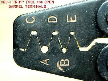
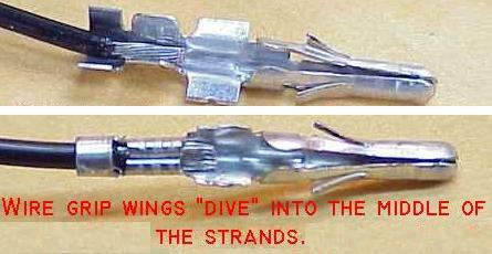
The BCT-1 hand crimper's different jaw sizes for different size connector pins. The "C", "D", and "E" pockets are used to crimp the bare wire to the Molex connector pin. These pockets cause the end of the pin's wire grip wings to curl over and dive into the center of the wire strands. Pockets "A" and "B" have a smooth circular shape, and can be used to crimp the terminal pin's insulation-grips into a "bear hug" around the wire's insulation, but Molex suggests using the C,D,E pockets for insulation too. Picture by aeroelectric.com |
|
-
For more details on connectors, crimping
and crimpers, please see
marvin3m.com/connect for details.
|
A Molex connector pin properely crimped.
Picture by aeroelectric.com |
|
3a. How to Use It: Electronic Schematic Symbols.
-
Though this isn't all the symbols ever used on a schematic,
these will certainly help.
|
All the symbols needed? Maybe... |
|
3b. How to Use It: Short Course in Transistors.
-
Transistors are used extensively in pinball. There are several types
used, but we will talk basics here to keep it simple.
What is a transistor? Transistors are tiny components which amplify small signals using low voltages. Transistors are basic components in all of today's electronics. They are just simple switches that we can use to turn things on and off. Even though they are simple, they are the most important electrical component. For example, transistors are almost the only components used to build a Pentium processor. A single Pentium chip has about 3.5 million transistors.
The transistor has three legs, the Collector (C), Base (B), and Emitter (E). The Base (B) is the on/off switch for the transistor. If a current is flowing to the Base, there will be a path from the Collector (C) to the Emitter (E) where current can flow (the switch is on). If there is no current flowing to the Base, then no current can flow from the Collector to the Emitter (the switch is off).
When current is put into the Base, it changes the voltage characteristics of the entire transistor, and so it is possible to control the current flowing from the Collector to the Emitter. So a small change of current on the base, results in a large change between the Collector and Emitter.
|
Transistor symbols: Note the arrow pointing in or out, signifying an NPN or PNP transistor. |
|
-
The arrow in the transistor symbol is always on the emitter leg, and points
in the direction of conventional current flow (positive to negative).
The easy way to remember which is which:
-
NPN = Not Pointing iN. The NPN transistor's arrow
is not pointing in.
PNP = Pointing iN Pointer. The PNP transistor's arrow points in.
NPN and PNP transistors function in essentially the same way, just the power polarities are reversed. This means a NPN transistor has a higher frequency response than a PNP transistor (because electron flow is faster than hole flow). When a NPN transistor is doing-its-thing, there is always a constant 0.6 volt drop between the base and emitter. That is, the base is always about .4 to .6 volts more positive than the emitter. We will see this come into play when we test transistors using a DMM (digital multimeter).
Bipolar transistors are often used in pinball, and are a current driven device. This means a very small amount of current flow from the emitter to base can control a relatitively large current flow from the emitter to the collector.
Darlington transistors (for example, the TIP102 and TIP36c) are actually two transistors in one package. This is achieved by arranging the two transistors so the emitter of one is driving the base of the next, and by connecting the collectors together. This is known as a Darlington pair, and can be used as any single transistor would be used (common emitter, emitter follower, etc.) The advantage to this style of transistors is it has a larger on-state power dissipation (which means these Darlingtons can handle lots of current for driving big pinball coils such as up-kickers and flippers). The down side to Darlington transistors is reduced power-on/power-off speed.
|
How a smaller current turns on a larger current in a NPN transistor. A Transistor can be thought of as a device that is active in only one direction: It can draw more or less current through its load resistor (sometimes referred to as a pull-up resistor). |
|
-
This above diagram shows how an NPN is turned on. When the base is turned off
(connected to ground), there is no current put through the transistor,
so the transistor is off.
When the base voltage is raised, it turns the
transistor on, completing the higher 12 volt's path to ground (and energizing
a pinball coil).
3c. How to Use It: Short Course in Logic Chips.
-
Like it or not, if doing circuit board repair, one must
know "what side is up" on logic chips. This document will not give
you all the details on logic chips, but does provide the basic things
info needed.
|
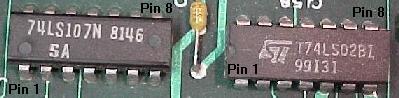
Two different chip makers mark pin one differently. The chip on the left (74LS107) has a small dot impressed to signify pin one. The chip on the right (74LS02) has a notch, and pin one is always to the left of the notch (as facing the chip's top side, with the notch up). The chip on the left also has a date code of "8146"; this chip was made during the 46th week of 1981. |
|
-
Pin One: where is it?
Every chip has a "pin 1". Find pin one, because this is the reference point for all the other chip pins. Also pin one is the reference point to how the chip should be inserted into the board or socket. Putting a chip in "backwards" will definitely cause the chip to fail!
Pin one on all chips is marked somehow. Often there is a small dot impressed into the case of the chip signifying pin one. Other times there is a notch in the chip showing pin one. In this case pin one is always to the left of the notch (as facing the chip's top side, with the notch up). Sometimes chips have both a notch and an impressed dot!
Pin one is also marked on all sockets too. Again, sockets generally use the "notch" in a cross bar for indicating pin one. This notch helps when replacing a chip, so it is not plugged in backwards! Some sockets use an indented cross bar to indicate pin one, instead of a notch.
Often the circuit board itself is also silk screened to show pin one for each chip. Again, this could be a box that shadows the chip, with a notch in one side of the box to show pin one. Or it could be as simple as a "1" or a "dot" next to the chip's pin one leg.
How are the Pins Numbered? (or where is the last pin?).
If pin one is found, the last pin is also found too.
Chips pins are numbers sequentially (as you hoped!), and
when there are no more pins on a side of a chip, the numbers
go directly across to the other side, and continue counting.
This means the last pin is directly across from pin one. Another
way to look at pin numbering is like a clock. If you are looking
at the top side of the chip with the chip's notch at
12 o'clock (and pin 1 is at 11 o'clock), the chip's pins are
numbered counter clockwise.
|
A 1996 ECG Master Replacement guide. You don't need the latest copy, as most chips you will be looking up have been around for a while. |

|
-
Buy a NTE or ECG Master Replacement Guide.
Any electronics dealer that sells NTE or ECG parts will have one of these guides available. Often older copy of this guide can be had for free, or just a couple dollars. The latest version is not needed, as most chips being referencing have been out for a number of years.
|
Information from the ECG Master Replacement guide. Note the Ground (GND) and +5 volt power (VCC) pins are shown, along with what the chip does and what the other pins do. Shown is a 7406 or 74LS06 chip. |
|
-
This replacement guide is not needed so much for the
chip replacement info (though that is certainly helpful!),
but for the chip "pin out" info in the book. It will show for
each chip, what the chip does, and what each pin does. This is
handy information to have. For example, the Ground (GND) pin
on many chips is different, as is it's logic power (VCC) of +5 volts.
This info is needed when doing circuit board repair, as
it is very helpful to know where ground and power (+5 volts)
is on any chip.
- 7400 (or 5400) Quad 2-input NAND gates.
- 7402 (or 5402) Quad 2-input NOR gates.
- 7404 (or 5404) Hex inverters.
- 7408 (or 5408) Quad 2-input AND gates.
Online Chip Reference Guides.
There are also some online chip reference guides with chip pin outs.
Though not nearly as good as the ECG/NTE replacement guides, the
online reference is quick and easy (and free!). Check out
http://www.embeddedlinks.com/chipdir
and http://www.twinight.org/chipdir/n/index.htm.
Explaination of TTL Chips.
The most common chip used in pinball circuits is the TTL chip.
TTL chips are a standard set of sub-circuits used in circuit board designs.
The TTL family of integrated circuits was introduced about 20 years ago by
Texas Instruments. TTL stands for Transistor to Transistor Logic, which signifies that
two transistors are used to drive each output of each chip, one for pulling
the output down to a low level, and one for pulling the output up to a high
level. Chips made using TTL technology are faster than the older RTL
(Resistor Transistor Logic) and DTL (Diode Transistor Logic)
families of integrated circuits, and they consume more power than the MOS
(Metal Oxide Semiconductor) technology used in most VLSI
(Very Large Scale Integrated circuit) chips.
The TTL family has at least six sub-families which offer different speed/power tradeoffs. These are summarized in the following table, where they are listed in roughly the order in which they were introduced:
| Family | Delay (ns) | Power (mW) | |
|---|---|---|---|
| basic | 10 | 10 | |
| Low-power | L | 35 | 1 |
| Schottky | S | 3 | 18 |
| Low-power Schottky | LS | 9 | 2 |
| Fast | F | ||
| Advanced Schottky | AS | 1.5 | 10 |
| Advanced Low-power Schottky | ALS | 4 | 1 |
| High-speed CMOS | HCT | ||
| High-speed CMOS | HC |
The term Schottky refers to a technology for making faster transistors. In each generation of the TTL family, the low power representative is about 3 times slower than the other member, but consumes about 1/10 the power. Today, the low-power Schottky (LS) subfamily is the most widely used member of the TTL family.
TTL chips have a standard naming convention of 74xx or 54xx. All manufacturers of TTL chips use this common naming system, as exemplified by the chip name SN74LS00. The prefix SN indicates that the chip was made by Texas Instruments; other manufacturers have their own prefix codes. However if the remainder of the chip name matches, the chips should perform exactly the same function. Additional one letter codes may be added as prefixes or suffixes to this code, for example, RSN indicates radiation hardened chips made by Texas Instruments, and SNM indicates the use of quality control procedures specified by the military specification MIL-STD-883.
The numeric code 74xx indicates that the chip conforms to the requirements of the civilian computer industry, being able to operate over a temperature range of 0 to 70 degrees C, while the code 54xx indicates the ability to operate over the more extreme temperature range of -55 to 125 degrees C required by many military and industrial applications. The letters LS (in the example SN74LS00) indicate which subfamily the chip belongs to. Finally, the last two digits indicate the logical function performed by the chip.
Here is a list of a few common TTL chips:
The descriptions of these circuits are based on the details given in The TTL Data Book published by Texas Instruments. Equivalent data books are published by all of the major chip manufacturers such as Signetics, National Semiconductor, ECG and NTE.
Each circuit description in the TTL collection follows a common scheme.
The input and output pins of the chip have numeric names corresponding
to the pin numbers used for a dual-in-line package; for example,
for a 14 pin chip, these are p1, p2, p3, and so on
up to p14. For any given chip, two of these pins are reserved for
power (+5 volts) and ground (0 volts); these pins are not included in the
chip descriptions. The remaining pins
are divided between input and output connections.
|
A 7400 chip. |
|
-
For example, consider the 74LS00 chip; this has four NAND gates. The inputs
of the first NAND gate are
p1 and p2, and its output
is p3. The inputs of the second NAND gate are p4 and p5,
and its output is p6. The remaining NAND gates are connected to
p8 through p13, and pins 7 and 14 are ground and power (respectively),
and are not given names in the specification.
HCT and HC Chips.
Most pinball applications use "LS" TTL style chips. But today LS chips
are becoming harder and harder to find. But the good news is the
newer HCT chips will directly replace LS technology in most
(if not all) cases. The "T" in "HCT" indicates a TTL LS level interface
(minimum 2.4 volts input for a logic "1"),
even though HCT is a CMOS device. HCT chips will usually
substitute for "regular" TTL chips too (like say a 7400 chip).
However don't sustitute HC for LS or any other TTL family without looking at the specifications, as HC chips are not compatible with TTL chips. They are high speed CMOS but with no TTL interface (HC chip expect much higher input levels for a logic "1" and a much lower input level for a logic "0"). The HC parts have similar interface levels to the old 4000 series IC's, except the HC parts usually run much faster.
CMOS Chips.
CMOS chips usually have the numbering convention of 40XX or 45XX.
The CMOS (Complimentary Metal Oxide Semiconductors) logic family is a step beyond the TTL family.
It's most notable feature is that it can operate at much higher voltages (over +12 volts) than a
TTL chip. Also it is ANALOG in it's performance, compared to the DIGITAL nature of TTL.
TTL's are considered digital as they have only 2 valid states: Low (0) and High (1).
CMOS have states that are proportional in nature.
For example, compare a CMOS 4069 Hex Inverter, which is a functional equivalent of the 7404 TTL (not "pin compatible", which mean you can't just plug a 4069 in place of a 7404). In this case, we know if a given input has a state of high (1) on the 7404 TTL, then it's output would be inverted to be low (0). After all, this is what a "Hex Inverter" does! But the CMOS 4069 would be different; first it's input state could be a voltage range from 0 to the operating voltage, say in this example, +12 volts. So if the input voltage for a given gate was +4 volts, then the output would be +8 volts, which is the inverse proportion of the input relative to the operating voltage (12 volts).
CMOS is useful for handling audio and video outputs, or any situation where the input voltage is not just a "black and white" zero or one.
3d. Component Explainations and How to Test Components Using a DMM (voltage, continuity, resistance, capacitance, diodes, transistors, chips).
Voltage.
-
A DMM has two leads, a black and a red lead. The black lead should
connect to the "COM" (common) connector on your meter. This is important
when measuring DC voltage.
Again, if the DMM has manual ranges, the range must be set above the voltage being testing. When measuring DC volts, the black DMM lead goes on ground, and the red lead on the voltage you are measuring. If measuring AC (alternating) voltages, this doesn't matter (since AC voltage changes from positive volts, to zero volts, to negative volts, back to zero volts, many times per second).
Continuity.
-
Continuity testing will be the most basic chore of a
DMM. Continuity testing check two points to determine if they are
directly connected to each other. Continuity is defined
as "zero ohms resistance", but in reality, most DMM's
define continuity as anything below 75 ohms of resistance.
For example, if I had to remove a chip from a circuit board and install a socket, I always test each pin of the socket to make sure it connects to the circuit board trace it is soldered. This ensures I haven't broken or cracked a trace while removing the old chip.
With my DMM set to "continuity", I can "buzz out" two points with the DMM's test leads. With one lead of the DMM on a socket pin, and the other DMM lead on the trace that connects to the socket, there should be a "tone" (or "buzz") indicating continuity. No buzz means these two points aren't connected (or are connected with high resistance).
If your meter does not have a continuity setting, just use the lowest range of resistance ohms for this test. Zero ohms (or close to zero, like less than 1 ohm) means you have continuity. The disadvantage to not having a continuity setting is you must LOOK at your meter to see if you have continuity. With a continuity setting, one only needs to HEAR the buzz tone, instead of seeing the meter. This makes checking continuity on a number of test points much faster.
-
Testing Resistance (Testing Resistors).
Resistance testing is much like testing for continuity, but usually the value of a resistor is being tested. If a manual range DMM is used, one will need to know the basic value of the resistor being tested (so the DMM's ohm range can be set accordingly). If the DMM is set to the 10k range, and the resistor being tested is 12k ohms, the meter will show no value.
Most resistors can be tested "in circuit". That is, with them soldered right in the circuit board (without removing them). Just put the leads of the DMM on either end of the resistor.
Are Resistors Polarized?
The short answer is "no", resistors are not polarized. When they
are being measured, it does not matter how the red and black leads
are positioned on the resistor. Likewise, when installing a resistor,
there is no "incorrect" orientation (it can be installed either way).
|
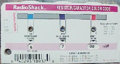
A Radio Shack resistor color decoder. Well worth the $1.19 for easy conversion of a resistor's colors. |
|
-
Resistor Color Chart.
Here is a resistor color code chart for the first three color bands of any resistor. The third band is the "multiplier" band:
| Band 1,2,3 Color | Band 1,2 Value | Band 3 Value (Multiplier) |
|---|---|---|
| Black | 0 | 1 |
| Brown | 1 | 10 |
| Red | 2 | 100 |
| Orange | 3 | 1 000 (1k) |
| Yellow | 4 | 10 000 (10k) |
| Green | 5 | 100 000 (100k) |
| Blue | 6 | 1 000 000 (1meg) |
| Purple | 7 | |
| Grey | 8 | |
| White | 9 |
-
Fourth Band Colors.
- No 4th band = 20% tolerance
- Silver = 10% tolerance
- Gold = 5% tolerance
- Red = 2% tolerance
- Yellow, Purple, Black, Silver = 47 ohms, 10% tolerance
- Yellow, Purple, Brown, Silver = 470 ohms, 10%
- Yellow, Purple, Red, Silver = 4700 (4.7k) ohms, 10%
- Yellow, Purple, Orange, Gold = 47,000 (47k) ohms, 5%
- Yellow, Purple, Yellow, Silver = 470,000 (470k) ohms, 10%
- Yellow, Purple, Green, Red = 4,700,000 (4.7meg) ohms, 2%
- Yellow, Purple, Blue = 47,000,000 (47meg) ohms, 20% tolerance (since there is no fourth band)
The last (fourth) band is the tolerance band (how accurate the resistor is to its stated value), plus or minus. Here are those colors:
Resistor Examples.
From the above bands, here is what a few
different resistor colors would be:
With the above info, a manual range DMM can be accurately set. Remember, always pick a DMM range higher than the resistor value being tested, but never lower. If a resistor is more than 10% above or below it's intended value, replace it (even though some resistors are rated at as much as 20% out of tolerance).
On-line Resistor Color Chart.
I have a nifty online resistor chart at
http://marvin3m.com/resist
for those that want to experiment with resistor colors and values
in a "point and click" fashion.
Resistor Wattage.
The bands of a resistor do not indicate the resistor's wattage. Small logic resistors
are typically 1/4 or 1/2 watt. Resistors used to handle supply voltages are usually
larger 1 to 10 watt resistors. Generally speaking, the larger the physical size of the
resistor, the higher the wattage and the higher current it can handle.
If an application calls for a 2 watt resistor,
only a 2 watt resistor or HIGHER will work (that is, 2 or 5 or 10 watts).
Installing a lower wattage resistor will surely
cause the resistor to become very hot and burn (making it go open or change resistance value).
Often higher wattage resistors are marked indicating their wattage (i.e. "5w" for 5 watts).
Smaller resistors are usually not marked with a wattage.
Resistor Values.
For the most part, resistors have a 10% "tolerance" rating. This
means if the circuit calls for a 33k (33,000) ohm resistor, an acceptable
value could go from 29.7k to 36.3k ohms (3300 ohms in either direction). Ideally it is best to
use a 33k ohm resistor. But in a pinball pinch, 10% above or
below the specified value is usually OK.
|
Measuring a diode with the black DMM lead on the banded side of the diode. |
|
-
Diodes are used extensively in pinball. In solidstate pinballs, there
should be a diode on every coil (some games, like the Williams WPC games,
have the coil diodes mounted on the driver board though).
The coil diode is used to suppress the the back EMF (Electro Magnetic Field)
voltage. When the power
to a coil is suddenly switched off, the collapsing magnetic field
generates a voltage across the coil which tends to maintain the current.
As the switch off is usually very fast, the voltage can reach several
hundred volts. This high voltage and current can travel back to the game's driver board,
damaging board components (usually the coil's driver transistor).
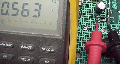
- Put the DMM on diode setting.
- Put the black lead of the DMM on the "+" (positive) terminal of the bridge.
- Put the red lead of the DMM on either AC bridge terminal. Between .4 and .6 volts should be seen. Switch the red DMM lead to the other AC bridge terminal, and again .4 to .6 volts should be seen.
- Put the red lead of the DMM on the "-" (negative) terminal of the bridge.
- Put the black lead of the DMM on either AC bridge terminal. Between .4 and .6 volts should be seen. Switch the black DMM lead to the other AC bridge terminal, and again .4 to .6 volts should be seen.
Testing Diodes.
A diode can not always be tested in-circuit. Often (but not always)
one lead of the diode needs to be remove (unsolder) from the circuit board
to get a good test. This also applies to testing coil diodes (one diode lead needs
to be removed from the coil). When testing diodes, use the diode test
of the DMM.
Put the black lead of the DMM on the banded side of the diode, and the red lead on the non-banded side. A reading between .4 and .8 volts should be seen. If a reading outside this range is noted, remove one lead of the diode from the circuit and test again. If still getting a reading outside of this range, then the diode is probably bad.
Switch the leads of the DMM (red lead on the banded side of the diode), and a null or zero reading should be seen on the DMM. If getting a different reading, remove one end of the diode from the circuit board and test again. If a null reading is not seen, the diode is bad.
Are Diodes Polarized?
The short answer is "yes", they are polarized. This means it does
matter which lead of the DMM is connected the "banded" or "non-banded" side
of a diode, as explained above. It also matters how the banded side
of the diode is oriented when installed in the circuit.
Diode Values.
Most general purpose diodes are rated at a peak voltage and number of amps,
and are used as a blocking diode.
This provides protection against repetitive reverse voltage
(DC Blocking Voltage.) For example when a coil de-energizes, it tries to back flow
power "up stream" to the driving circuit, sometimes in voltage twice the
energizing voltage. To block this back flow of power,
snubbing diodes are used.
Remember a higher amp and/or higher voltage diode can usually be substituted. For example, a 1N4001 diode is rated at 1 amp 50 volts. A 1N4004 diode, rated at 1 amp 400 volts, can be used in its place (the most commonly used diode in pinball is the 1N4004). Bridge Rectifiers (essentially four diodes in one package) are the same way (an increase in peak voltage and/or amps is OK). In pinball 1n4001 diodes are often used on 12 volt switch matrix switches, and 1n4004 diodes are used on 30 to 70 volt coils. But in either application, a 1n4004 diode will work fine.
Zener diodes can not be substituted as easily. These diodes are rated at a particular voltage and wattage. This voltage in nearly all circuits must be the same. Only the amp rating can be increased. For example, a 1N5237 zener diode is an 8.2 volt 1/2 amp Zener diode. A 1N4738 can work too, as it is 8.2 volts but at the a higher 1 watt power rating). And a 1N4196 (8.2 volt 10 amps) could be substituted because it still maintains the 8.2 volts, but at 10 amps. In most pinball applications 1/2 or 1 watt zener diodes are common (I personally always replace a 1/2 wat 1N52xx zener diode with a 1 watt 1N47xx version).
| Zener Diodes, 1/2 versus 1 Watt | ||
|---|---|---|
| Diode Voltage |
1/2 Watt (1N52xx) |
1 Watt (1N47xx) |
| 2.4 | 1N5221 | none |
| 2.5 | 1N5222 | none |
| 2.7 | 1N5223 | none |
| 2.8 | 1N5224 | none |
| 3.0 | 1N5225 | none |
| 3.3 | 1N5226 | 1N4728 |
| 3.6 | 1N5227 | 1N4729 |
| 3.9 | 1N5228 | 1N4730 |
| 4.3 | 1N5229 | 1N4731 |
| 4.7 | 1N5230 | 1N4732 |
| 5.1 | 1N5231 | 1N4733 |
| 5.6 | 1N5232 | 1N4734 |
| 6.0 | 1N5233 | none |
| 6.2 | 1N5234 | 1N4735 |
| 6.8 | 1N5235 | 1N4736 |
| 7.5 | 1N5236 | 1N4737 |
| 8.2 | 1N5237 | 1N4738 |
| 8.7 | 1N5238 | none |
| 9.1 | 1N5239 | 1N4739 |
| 10 | 1N5239 | 1N4740 |
| 11 | 1N5241 | 1N4741 |
| 12 | 1N5242 | 1N4742 |
| 13 | 1N5243 | 1N4743 |
| 14 | 1N5244 | none |
| 15 | 1N5245 | 1N4744 |
| 16 | 1N5246 | 1N4745 |
| 17 | 1N5247 | none |
| 18 | 1N5248 | 1N4746 |
| 19 | 1N5249 | none |
| 20 | 1N5250 | 1N4747 |
| 22 | 1N5251 | 1N4748 |
| 24 | 1N5252 | 1N4749 |
| 25 | 1N5253 | none |
| 27 | 1N5254 | 1N4750 |
| 28 | 1N5255 | none |
| 30 | 1N5256 | 1N4751 |
| 33 | 1N5257 | 1N4752 |
| 36 | 1N5258 | 1N4753 |
| 39 | 1N5259 | 1N4754 |
| 43 | 1N5260 | 1N4755 |
| 47 | 1N5261 | 1N4756 |
| 51 | 1N5262 | 1N4757 |
| 56 | 1N5263 | 1N4758 |
| 60 | 1N5264 | none |
| 62 | 1N5265 | 1N4759 |
| 68 | 1N5266 | 1N4760 |
| 75 | 1N5267 | 1N4761 |
| 82 | 1N5268 | 1N4762 |
| 87 | 1N5269 | none |
| 91 | 1N5270 | 1N4763 |
| 100 | 1N5271 | 1N4764 |
| 110 | 1N5272 | none |
| 120 | 1N5273 | none |
| Diode Voltage |
1/2 Watt (1N52xx) |
1 Watt (1N47xx) |
| Zener Diodes, 1/2 versus 1 Watt | ||
Testing Bridge Rectifiers.
A bridge rectifier is essentially four diodes assembled inside a
"black box". The bridge's job is to take AC voltage and rectify it to DC voltage.
This is a very common component in pinball repair.
Note testing a bridge is *not* conclusive to whether the bridge is bad!
The bridge is being tested under NO load. Only a bridge which is shorted
(and hence is blowing fuses) or open will test as "bad". A bridge could test as
"good", and still not work properely. Also testing a bridge "in circuit"
(while still soldered in the board) can often not give proper results.
A bridge has four terminals: two AC terminals, and two DC terminals (postive and negative). On the side of each bridge, printed on the metal casing, there should be two labels: "AC" and "+" (also the "+" lead should be offset in position compared to the other three bridge leads). Figuring out the other two terminals is easy: the other AC terminal is diagonal to the labeled AC lead. The negative DC lead is diagonal to the labeled (and offset) positive DC lead. Testing a bridge while soldered in the board (in curcuit) may not give the following results. To test the bridge:
If values outside of .4 to .6 volts are shown for any of the above tests, the bridge is bad. Typically seen is a zero value (a short) or a null reading (a bridge diode is open) in at least one of the above tests.
Transistors and Chips.
-
Transistors are essentially electronic switches. And TTL chips (Transistor to Transistor
Logic), which are used extensively in pinball circuit boards,
are basically a group of transistors packaged into a chip).
Testing Transistors.
Testing transistors works much like testing diodes.
Use the DMM's diode test. The individual electronic pinball repair guides
cover all the transistor testing needed. See each repair guide
for specific details. Some DMM's have a separate transistor tester. This
works fine too, but requires the transistor be unsoldered from the board
to use it (extremely inconvenient).
For the most part, the most common testing will be on "darlington" transistors (which means they are actually two transistors in one package) such as the TIP102, TIP122, TIP36 transistors. Also most testing is done "in circuit" (installed in the circuit board). For each of these have one lead of the DMM on the metal case (tab) of the transistor (which is usually the center leg of the transistor). Then the other lead of the DMM will test the outside two legs individually. A value of .4 to .6, or 1.0 to 1.2 should be seen, depending on the exact transistor, and which lead (red of black) is on the metal tab. The biggest indicator of a bad transistor would be a value less than .2 (probably a short). Look to the specific pinball repair guides for more exacting details of this. Also remember, a transistor can ocassionally test as "good", but in fact be bad.
Testing Chips.
The DMM's diode test mode can also be used to check most logic
chips. It's best to test chips out of circuit, but frankly this just
isn't possible most of the time.
To test chips, the ground leg of the chip in question will need to be known (that's why we went through the "short course on logic chips" above). Then put the RED lead of the DMM on this ground leg. Yes I know, it sounds weird. "Why the RED lead on the ground leg? Isn't that backwards?" Backwards or not, that's how to do it. With the red lead on the ground pin, check all the other pins (except for VCC, which is the chip power pin) with the black lead of the DMM. Again .4 to .6 volts should be seen for each leg. If a different value is seen, chances are the chip is bad. The biggest indicator of a bad chip would be a value less than .2 (probably a short).
|
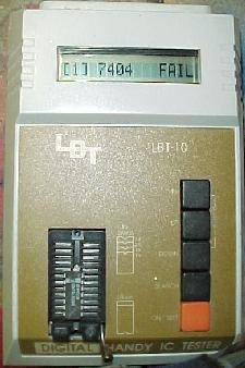
The LBT-10 (Lil' Bitty Tester) chip tester. |
|
-
Another more advanced way to test chips is using a box called the
LBT-10 made by Lil' Bitty Tester. Available from MCM Electronics (800-543-4330),
these cost about $200. But in my opinion, it's worth every penny. If
the chip in question can be removed from the circuit board without damage, the LBT-10
will test any TTL (Transistor to Transistor Logic) family of chip (7400
to 74xxx and their LS, S, HTC, etc. cousins).
It also tests CMOS chips (40xx and 45xx series), which is *really* handy too!
It works fast and is extremely easy and reliable to use.
I *highly* recommend this product, especially for a newbie.
The only disadvantage to this box is the chip needs to be removed
from the circuit board to be tested, and of course the price.
ABI in the United Kingdom makes a more advanced (and more expensive)
version of the LBT-10 called the
ChipMaster Compact.
I am still looking into this product.
Chip Numbers.
For the most part, if a circuit calls for a 74LS04, it should only be
replaced with a 74LS04. But sometimes other chips can be used, as long
as it is in the same "family". That is, logically these chips are all
the same (a hex inverter), but their power or speed specifications may
be different.
But that is not saying that a circuit that used a 7404 originally will
work with a 74HTC04. Often it will, but many times it will not. It just
depends. For example, a timing circuit could react differently with a
7404 versus a 74LS04. More information on this can be found in the
Short Course in Logic Chips above.
-
Capacitors store electrical charges for just a moment. These
are used in pinball for filtering, making a rough signal or voltage more uniform
and flat (the supplying voltage charges the capacitor, and as the
voltage falls, the capacitor discharges, keeping the voltage at
a certain level until the supplying voltage increases again).
- F : Farad.
- mF : millifarad, or one thousandth of a Farad.
- uF or mfd : microfarad, or one thousandth of a millifarad.
- nF : nanofarad, or one thousandth of a microfarad.
- pF : picofarad, or one thousandth of a nanofarad.
Capacitor Values and Terminology.
Capacitors are measured in some derivative of a Farad.
For example, the caps in
most pinball games are measured in "microfarads"
(occasionally picofarads will be specified, but that is fairly rare).
The proper way to designate 100 microfarad is "100uF" or "100 mfd".
Here's a breakdown of capacitor terminology:
For a comparison, .039 microfarad (uF) is the same as .000039 millifarads (mF).
Another confusing thing about caps are how they are sometimes labels. For example, often ceramic capacitors will say "104" on them. Most caps will have three numbers, but sometimes there are just two numbers. These are read as Pico-Farads. An example, "47" printed on a small ceramic cap can be assumed to be 47 picofarad. If there are three numbers, it is somewhat similar to a resistor code. The first two numbers are the first and second significant digits, and the third is a multiplier code. Most of the time the last digit tells you how many zeros to write after the first two digits (in picofarads), but the standard has a couple of curves. To be complete here it is in a table:
| 3rd Digit | Multiplier (this times the first 2 digits give the value in picofarads) |
|---|---|
| 0 | 1 |
| 1 | 10 |
| 2 | 100 |
| 3 | 1,000 |
| 4 | 10,000 |
| 5 | 100,000 |
| 6 | not used |
| 7 | not used |
| 8 | .01 |
| 9 | .1 |
Example: A cap marked "104" is 10 with 4 more zeros or 100,000 pF, which is otherwise referred to as a .1 microfarad cap. A cap marked "103" is 10 x 103 pF or .01 microfarad. Likewise "102" is 10 x 102 pF or .001 microfarad. Here's a table for ease:
| Cap Value | Cap Code |
|---|---|
| .0001uF or 100pF | 101 |
| .001uF or 1000pF | 102 |
| .01uF or 10,000pF | 103 |
| .1uF or 100,000pF | 104 |
| 1uF or 1,000,000pF | 105 |
| 220pF | 221 |
| 560pF | 561 |
| 880pF | 881 |
| .02uF | 203 |
| .2uF | 204 |
| 2uF | 205 |
| .022uF | 223 |
| .22uF | 224 |
| 2.2uF | 225 |
| .047uF | 473 |
| .47uF | 474 |
| 4.7uF | 475 |
In addition there can be a letter after the cap code. This tells the tolerance of the capacitor:
| Letter symbol | Cap Tolerance |
|---|---|
| B | +/- 0.10% |
| C | +/- 0.25% |
| D | +/- 0.5% |
| E | +/- 0.5% |
| F | +/- 1% |
| G | +/- 2% |
| H | +/- 3% |
| J | +/- 5% |
| K | +/- 10% |
| M | +/- 20% |
| N | +/- 0.05% |
| P | +100% ,-0% |
| Z | +80%, -20% |
For example, a cap marked "33J" would be a 33 picofarad cap with +/- 5% tolerance.
Electrolytic Caps - Radial or Axial?
Electrolytic capacitors come two different styles, radial or axial.
Radial has both leads at one end of the cap, and the cap usually mounted
vertically. Axial has the leads coming out of opposite ends of the cap,
and these usually mount flat against the circuit board. Axial style
are more common on the older games. I remember axial caps as having the
leads on different ends by thinking of the earth, and how it rotates
on its axis, with the axis sticking out of the earth at both north
and south poles, like the leads on an axial capacitor.
Testing Capacitance - Testing Capacitors.
Testing capacitors is tricky. The problem is most capacitors need to
be tested under full load to really determine if they are bad. Any
capacitance test a DMM does will not do this.
Also one lead of the
cap will need to be removed from the circuit board when testing.
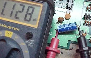
|
Testing a 1000 mfd electrolytic capacitor. The meter indicates 1128 mfd, meaning this cap is probably good. Note one lead of the cap is removed from the circuit board for the test. |
|
-
If you are testing a 1000 mfd capacitor, it must test higher than
that value to be considered "good". Anything lower than its stated
value, and that capacitor should be replaced.
Of course the best way to test a capacitor is to just replace it with a new one! This isn't always cost or time effective, but it is really the best course of action if a capacitor is suspected as bad.
The Best Capacitor Tester - the ESR Meter.
There is yet another way to test capacitors.
Called the ESR (Equivalent Series Resistance) or low ohms meter,
this is the best way to test caps.
This nifty device allows testing capacitors
in-circuit, with extreme reliability. This works especially
good for repairing video game monitors and power supplies, but is also useful
for pinball. Testing of all the caps on a circuit board can be done in seconds,
without removing the caps.
The best deal on an ESR meter is the Dick Smith ERS, available at anatekcorp.com/testequipment/esr.htm. It's about $130 fully assembled. This is generally considered the best ESR meter, especially for the price. Also available is the Capacitor Wizard at about $200. Another assembled meter is the CapAnalyzer 88A, sold by MCM Electronics (800-543-4330), part number 72-6508, $179.
Are Capacitors Polarized?
The short answer is "sometimes". Capacitors that are polarized will
have some marking indicating the negative or positive lead. Capacitors
that are not polarized, won't have any negative or positive markings.
Often the negative lead is indicated with just a black line down the
side of the capacitor. Also often one of the capacitor's leads (on a new
cap) will be longer than the other (to signify polarity).
If testing an electrolytic capacitor (which has "polarity"; marked positive and negative leads), make sure to put the red lead of your DMM on the positive lead of the cap when testing.
Similar Capacitor Values.
In most cases it is OK to increase the voltage a capacitor is rated.
For example, if a 1 mfd 16 volt capacitor is specified, a 1 mfd 25 volt capacitor
can be used.
Usually it is not OK to change the Farad value of the capacitor, but
small amounts can be changed. For example
if a .49 mfd cap is specified, a .5 mfd cap can be
used in it's place. Also never substitute
a non-polarized capacitor in a circuit that is specifying a polarized cap.
Some Williams solidstate games use an inductor or choke, which is mearly wire wrapped around a ferrite core. An inductor filters or chokes out certain signals (frequencies). Inductors are measured in microhenries, and are most often denoted as "L", which is the inductance in microhenries (mH). Nanohenries is denoted as nH. For example, a 10 microhenries (mH) inductor is used on the B.S. Dracula long-range opto board.
Other Component Testing Info.
For more info on testing electronic components with a DMM, check out
http://www.repairfaq.org/REPAIR/F_Repair.html and
http://fribble.cie.rpi.edu/~repairfaq/REPAIR/F_semitest.html and
http://fribble.cie.rpi.edu/~repairfaq/REPAIR/F_captest.html (capacitor testing).
3e. How to Use It: Logic Probe.
-
Learning to use a logic probe is a bit tricky. First,
find power for your logic probe. Most probes work on +5 to +12 volts DC.
The probe will have a black ground wire that
connects to ground, and a red wire that connects to power (+5 to +12
volts DC). After power to your logic probe if found, any chip pin can be "probed"
(with the metal pin probe of the logic probe),
on a powered-on circuit board. If the probe has a "TTL/CMOS"
switch, use the "TTL" switch setting. (More on the CMOS setting
later.)
Finding Power Points for the Logic Probe.
Since logic probes derive their operating power from the PCB under test,
care should be taken in attaching the clips to safe voltages.
First use a DMM (Digital Multi Meter) to
verify the hook up points have good voltages. Actually if a repair person
is at the point of using a logic probe, they should have already
verified the board under repair has good voltages! Low or no voltage (such as
+5 volts) is a common problem, and a DMM should be used to find that.
Probes have two power clips: black for ground, and red for power (+5 to 12 volts). With the game turned off, connect these leads to known good voltage points. Then power the game on. On pinball games, I like to find power "test points" on the driver board. I use the +5 volt test point for the red lead of the logic probe, and attach the black lead to a ground test point (or even the metal ground strap in the head).
|
The Wittig Technologies osziFOX probe in action. It is showing a "pulse". |
|
|
-
"Probing" with the Logic Probe.
- RED: High logic state (a binary 1). TTL chips consider +2.4 to +5 VDC to be high.
- GREEN: Low logic state (a binary 0). TTL chips consider 0 to + 0.8 VDC to be low.
- YELLOW: Pulsing state (moving between a binary 0 and 1 quickly).
First make sure the "TTL/CMOS" switch on the logic probe is set to "TTL". Then after the logic probe has power, the metal "point" on the logic probe is now touched to pin on a chip in question. BE CAREFUL! Don't touch two chip pins at once, shorting them together! If this does happen, I personally turn the game off and start over (and hope nothing is damaged, which is usually the case).
The logic probe will tell if the pin chosen is either "high" (at +5 volts), "low" (at zero volts), or "pulsing" (changing it's state quickly from high to low, or vice versa). This information is important, as seen in our working example below. For example, with a logic probe, it can be seen if the CPU chip is "running" (pulsing), or if it is locked in a high or low state.
Unfortunately, a logic probe only indicates state changes (a zero or a one, which is 0 volts to .8 volts, or 2.4 volts to +5 volts, respectively). It is up to you to know if these are the expected changes!
Logic Probes usually have three LED's (and some have a buzz tone too). The 3 LED's indicate:
Using the Logic Probe.
For this example, I will be using a 1990 to 1999 Williams/Bally WPC pinball
game.
Before starting, the game's schematics are absolutely necessary. So grab those, and open up to the CPU board's schematics. The board has already been checked for proper voltage (it does have a good +5 volts, right?). The logic probe should be connected to a good power source on (or near) the board (on a WPC board, use the driver board power test points).
Turn the game on (make sure the "TTL/CMOS" logic probe switch is set to "TTL") and test the probe by touching the tip to a +5 volt power source on the CPU board. A solid, steady red LED should be seen, indicating high (some probes may also have a tone). On a WPC pinball, I personally like to test pin 40 of U4 (+5 volt power to the CPU chip) for a high signal.
Next probe a ground point on the board. A solid steady green LED should be seen, indicating low state. Again on a WPC pinball example, I personally like to test pin 1 of U4 (ground for the CPU chip) for a low signal.
Now that the logic probe is tested, it's time for some real work! Look at the schematic, and find the RESET pin for the CPU processor. For an example, looking at a Williams WPC CPU schematics, it's processor is a 68B09 at position U4 on the CPU board. The schematics label the reset pin as "RST", which is pin number 37 of chip U4. Probe the RESET pin; the logic probe should indicate a High state (red LED). When the game is first turned on, the reset line should be low, and then go high and stay high. This is pretty much how all reset lines work on any CPU; if the reset line is pulled low, the CPU resets and goes back to being high.
To power off just the WPC CPU board, leave the game's main power switch on, and remove CPU connector plug J210. This will power the CPU board off. With the logic probe on pin 37 of U4, the pin should be low. Replace plug J210, and the CPU board will "boot". Pin 37 of U4 should, after just a moment, go high and stay high.
Simple enough, right? So now probe pins 8 to 23 of chip U4 (any one of those, not necessarily all of them). These are the address lines A0 to A23, respectively. The logic probe should show these pins as pulsing. Likewise pins 24 to 31 are the D0 to D7 data lines. Any of these should show a pulsing signal too. Probing these address and data lines shows that the CPU chip is "doing work", accessing memory and moving data.
When to use CMOS Setting.
The CMOS setting is for chips that are dealing with slightly
higher voltage. Like LM339 voltage comparitor chips used
in Williams/Bally switch optic circuits. The optics are powered by
12 volts, and 10 to 12 volts is a "1", and 0 to 2 volts is
a "0" (the LM339 voltage comparitor interprets the voltage, and outputs
a "0" or "1" to the CPU board's switch matrix.)
In this case, since you're dealing with 12 volts,
the CMOS setting on the probe should be used.
A Real Life Pinball Example (more Probing Fun).
Let's take a real life example of how a logic probe can be used
in pinball repair. For our example, a 1990 to 1999 Williams WPC pin game is
displaying the message "row 1 switch matrix short" on the display. We have concluded the
problem is not in the playfield (since we removed all the CPU's switch matrix row playfield plugs J208, J209, J212,
and the error still displays at boot-up).
Test the Input Side.
With the logic probe connected to the game, go into diagnostic test mode. Specifically,
enter the first switch test. Now find the switch matrix ROW chips on the schematics. In the
case of a WPC game, these are the LM339 chips (quad comparator) at U18 and U19.
In this example, pin 11 of U18 is row one of the switch matrix, pin 9 is row two,
pin 5 is row three, and pin 7 is row four. To make sure none of the switches in row one are
activated, remove the connector plugs at J208, J209 and J212 (the playfield switch matrix
row plugs). The display should show all switches as "open" (dots).
Put the logic probe on pin 11 of U18 (switch matrix row one).
This pin should be high.
To simulate a short to row one of the switch matrix (a fairly common problem), get an alligator clip jumper wire. Connect one end of the alligator clip jumper wire to pin 1 of connector J208. Connect the other end to ground (metal ground strap at the bottom of the backbox). The display should immediately show all switches in row one as closed ("boxes").
Now probe pin 11 of U18 again. The logic probe should indicate low. Remove the jumper wire from ground, and pin 11 should go high again. Now remove connectors J206 and J207 (the switch matrix column connectors). Touch the alligator jumper wire from J208 pin 1 to connector J206 pin 1 (this is column one of the switch matrix). Pin 11 should now have a "high pulse" (pulsing, but still mostly high).
Test the Output Side.
So far we have just probed the "input" side of the switch matrix
row one. Now look at the schematics, and see that the input pin 11 of U18 has
an output at pin 13. With all the connectors removed from above, also
remove the alligator jumper wire from J206 pin 1.
Now probe pin 13 or U18. A "high" signal should be seen.
Again touch the alligator jumper wire from J208 pin 1 to connector J206 pin 1 Pin 13 should now have a "high pulse". Also the display should indicate row 1 column 1 (switch 11) as closed (a "box").
Conclusion.
With the connectors removed, we knew input pin 11 of U18 should be high (and go low
when a row one is shorted). If it does not do this, the problem
could be as simple as a broken trace or a bad feeding diode at D3 to the chip at U18.
If the input side of U18 acts correctly, but the output side does not, we know the chip
U18 itself has failed and needs to be replaced.
Using this input versus output probing technique, failed chips can be found. The only problem in the equation is the repair person must know what the signals should look like in a working game! That's a big problem, but often the schematics or probing a working game can reveal these secrets. Here experience is the best teacher. Working with a logic probe is the only way to get experience.
3f. How to Use It: Soldering a Circuit Board.
-
Here are some
tips on what to do (and not do) when soldering circuit boards.
NOTE: only use 60/40 (tin/lead) rosin core solder on electrical connections!
And use the right soldering iron for the job (as discussed above).
What Exactly is Soldering?
Soldering is the joining of two metallic surfaces
with an added metal alloy, of a *lower* melting point
(this is different than welding, which is the joining
of two metal surfaces at their melting point). Soldering
is an ancient art used to make jewelery, connect pipes,
and to make electrical connections.
The alloy that we know as "solder" is made of various metals. For jewelery, the solder's metals are usually silver and gold. For plumbing and electrical work, lead and tin are usually used. Because we are discussing electrical work, only lead and tin solder will be discussed here.
Electrical solder is usually a combination of 60 percent tin and 40 percent lead (or even 63 percent tin and 37 percent lead). Electrical solder also has a hollow core that contain a rosin "flux".
The flux melts at a lower temperature than the solder itself. Its purpose is to prepare the surface for soldering. It does this by removing oxides from the metals to be joined. It also prevents the heated metals from oxidizing as they are heated. Oxides form when metal is exposed to air. Even "corrosion-proof" metals like stainless steel can oxidize.
When soldering, the molten solder joins metallic surfaces by dissolving into the metals and forming a amalgam (mixture) with them. Often the soldered joint is stronger than the individual components it holds together.
But this mixing of metals can only occur with surfaces free of oxidation and other contaminants. Oxidation can be removed by sanding the parts first, but some chemical cleaning is still needed, since as the parts are heated oxidants can form. The rosin flux is the chemical cleaner.
The rosin flux core in 60/40 solder can normally do all the cleaning necessary on new parts or pre-tinned parts (pre-tinning is the process of adding solder to a part before it is joined to another). But there are some conditions when the rosin flux core is not enough.
The perfect example of this is trying to solder a circuit board that had battery corrosion. Oxides (caused by the battery corrosion) prevents solder from joining with the metals. Oxides also prevent heat transfer. Even a thin layer of oxides can act like an insulator, reducing the heat flow from the soldering iron to the metal(s). The only way to solder a circuit board that had battery corrosion, is to sand the corrosion off, leaving bright and shiny copper traces behind (this also assumes the battery corrosion was first washed with a vinegar solution, to neutralize the battery's base).
When solder isn't sticking to the joint surfaces, it tends to ball-up like mercury. If solder doesn't have anything better to stick to, it sticks to itself. Solder in a bad solder joint can sometimes only be held in place by the rosin flux! Properely soldered joints tend to have a very slight concave appearance. The solder feathers out to a thin film when heated. This happens because molten solder flows towards the heat source. If a joint is clean, the right amount of heat applied, and a good 60/40 rosin core solder used, the solder will flow through the joint easily. Also don't be mislead that "more is better" when it comes to soldering. Too much solder can cause problems too.
Cold Solder Joints.
Another thing that must be watched for when soldering is
the crystallization of solder, as it changes from liquid
to a solid. If the solder joint is moved
at the point the solder solidifies, crystals can form
that have high resistance. This is known as a "cold" solder
joint. On circuit boards, this can cause the circuit to fail!
To prevent cold solder joints, keep the joint still before,
during, and after soldering.
A Clean Connection.
The connection being soldered must be clean. If the circuit
board pad has any corrosion or old flux, clean it off first
before soldering. Use a sanding pen (available at automotive
paint supply stores) or a small metal brush or even fine grit (400) sandpaper.
In some cases, the green "solder mask" may need to be sanded off the copper traces to solder.
Radio Shack also sells a cleaner and degreaser solution (part number
64-4322, $12.99). Alcohol also works well for cleaning parts.
Most circuit board connections will be clean, but if they aren't,
clean them first BEFORE you try and solder. Flux, which is inside
rosin core solder, will melt with the heat of the soldering iron, and will
clean the metal of oxidation you didn't remove. This allows the solder
to flow easily. But don't think the flux will solve all the dirt problems,
because it won't! Dirty surfaces won't allow solder to flow, which means
you won't get a good solder joint.
A Good Mechanical Connection First.
The components should be secure before attempting to
solder them. Solder is not strong, and should not be relied on to
"hold" components together. The parts should not be able to move in
relation to each other.
When installing components, bend the component leads so they go straight into the printed circuit board holes. Components should go in gently; don't jam them in as some components can be damaged easily. Don't pull the leads through the board; instead push the component into the board (pulling leads can damage the component). Double check the component's value before installing it. If the component is polarized (many capacitors and all transistors and all diodes), make sure to install it correctly (yes it often does matter which way the part goes!) Most components should be mounted snug against the board. There are some exceptions though. Any component that could run "hot" should be installed with air clearance below the component. Typically this applies to resistors, diodes and transistors. Before soldering the component, double check the value, orientation and position. It's easier to fix a problem now than after solder has been applied.
Examine the Un-Soldered Connection Before Soldering.
Inspect the connection. Make sure you know where the new solder
is supposed to go. If there is another solder pad very close
to the one you are soldering, make a mental note.
Make sure no unwanted solder makes a "bridge" from the desired connection
to the adjacent one. If a mental note in not made, sometimes it's
hard to tell if two solder pads should or should not be connected.
"Tin" Your Soldering Iron.
After the soldering iron warms up, apply some solder
to all sides of the tip. Then wipe the solder off with a clean rag.
This will "tin" the tip with a nice shinny coating
of solder. The solder should not "ball up" and drop
off the tip. Do this first right after the soldering iron
warms up. This prevents oxides from forming on the tip,
and allows heat to be easily transferred from the soldering
iron to the joint being soldered.
Do this often when soldering to keep the
tip clean and heat efficient.
Heat the Joint.
The basic principle of soldering is to apply heat to the items
being soldered, then apply solder to the heated items. The solder
should melt upon contact with the items (do not apply the solder
to the soldering iron's tip).
Apply the tapered surface of your soldering iron's tip to the connection being soldered. The tip should *not* be perpendicular to the solder joint, but at an angle (for greater surface area contact of the tip). It's better to directly heat the circuit board pad, instead of the component leg itself (most electronic components are heat sensitive). Allow the joint to become hot (a second or two), then apply the Rosin core solder to the JOINT (not to the iron's tip!). I usually apply solder to the circuit board pad, and solder will spread across the pad, allowing heat to transfer more efficiently across the joint and to the component's leg. After the solder begins to flow, lift the iron's tip away from the joint carefully, keeping the joint stable.
|
|
|
-
More on Cold Solder Joints.
There are some important things to remember here. First, let the joint melt the solder, not the iron's tip itself. Second, keep the joint stable until the solder solidifies. If you fail at either of these two point, you may create a "cold" solder joint (a solder joint that fatigues, cracks or becomes non-conductive later; the term "cold" came about because there wasn't enough heat used to solder the connection). A cold solder joint will not provide a good electrical connection. When the solder solidifies, it should be shiny. A gray solder joint indicates either not enough heat was applied, or the joint moved while the solder was solidifying (making an instant "cold" solder joint that will probably fail later).
|
|
|
-
Too much Heat.
Soldering a circuit board with too much heat can "lift" (delaminate) the traces from the circuit board. Traces are the thin metal "wires" that connect the components electrically to each other. These traces are basically epoxied to the circuit board. If you apply too much heat to a solder pad, it will delaminate the pad and it's connecting trace. Though a lifted trace can be tediously repaired, this is the easiest way to ruin a circuit board.
The Right Amount of Heat.
One of the more important thing to remember about
soldering on circuit boards is to keep the amount
of heat applied at a minimum. Don't "overheat"
the solder joint, as this can lead to traces lifting or
breaking. But you also must apply enough heat so the solder
joint isn't "cold". This is why practice makes perfect.
Get the right feel for soldering with enough heat, but not too much,
takes some practice (use a scrap circuit board).
If the solder joint is clean, and the iron's tip "tinned",
than there should be no problem soldering with a minimal
amount of heat.
The Right Amount of Solder.
When soldering, don't apply too much solder, and
don't apply too little. If the solder pad is "puckered" when
you are done soldering, too little solder has been applied.
If the solder mount is a round mountain, too much solder was added.
There should be a small "hill" of solder on the pad, but not excessive.
Again, practice will help develop an eye for
applying the right amount of solder. Again, a slight mound
of solder is wanted on the solder joint, but not too much. Be conservative,
but don't leave puckered solder joints either.
|
Left: Flux remover solution with a neat brush applicator. Middle: The shinny flux after soldering. This flux needs to be removed. Right: After the flux has been removed with flux remover solution. |
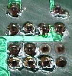
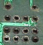
|
-
Cut the Component Leads.
Use cutting pliers and cut the excess component leads. Cut them at about the point where the solder has risen up the component lead. Do NOT cut into the solder mound on the circuit board! This can cause the solder joint to crack later, and fail electrically.
Remove the Flux after Soldering.
After you are done soldering, remove the flux. Flux will be a shinny
area around the joints you have soldered. Some flux is conductive, or
it can hold metal filings inside the flux that can short traces.
The best way to remove old flux is to use a Rosin flux remover solution
(available at Radio Shack). Or you can use Acetone (available at
hardware stores) or 99% rubbing Alcohol and
a toothbrush, which works quite well too. Don't go crazy doing this
though; you can cause problems too by being too aggressive (and breaking traces). Of course
let the board dry before you apply power to it.
Inspecting the Solder Joint.
When finished, inspect the new solder joint. Use a
lighted magnifying lamp, and make sure the connection is
good and looks like the figure above. Make sure the solder hasn't
flowed to any adjacent pads or traces. If it has, "desolder" the mistake(s).
3g. How to Use It: DeSoldering a Circuit Board (Chip Sockets & Installing/Removing Chips).
-
Desoldering is an art form. Plenty of practice is needed to
perfect the art. So break out some junk PCB boards, and let's
try out the new desoldering tool.
IMPORTANT: Keep this in mind when Desoldering!
The biggest problem with desoldering is ruining the circuit
board itself! Most circuit boards can NOT take more than one
or two desolderings at any particular solder pad. Excessive heat
will cause the board traces to lift or crack. Once this happens,
it becomes more difficult to repair the board, often because a
cracked trace may not be easily seen. A circuit
board can easily be ruined with excessive heat from desoldering.
Always install a new Socket!
When desoldering chips, always replace the chip with a new
high quality socket. Again, circuit boards can't take too much desoldering.
A good quality socket will solve this problem forever, so
no additional soldering/desoldering will ever be needed at that location.
Desoldering the "HARD" Way.
Often, the neophyte user will have the right tools to desolder,
but not the right technique. They will attempt removing a failed
chip, the "hard" way. Usually they attack the board directly,
and just unsolder the part using their
favorite desoldering tool. This usually leads to lifted or broken solder
pads and/or traces. Or ripped plated-through holes.
Often the neophyte doesn't even realize
they have done this. Of course they install a new socket for the chip
(as they should), but this just clouds the issues further. Now the lifted/broken
trace(s) can not be seen as it's underneath the socket! The board of course
doesn't work, and is sent to a professional repair facility. They in turn
get mad as hell, as fixing someone else's mistakes is very time consuming,
and the customer gets charged a small fortune.
|
The "Hard" way: here the solder pads are desoldered using the neophytes favorite desoldering tool. The work looks good; the bottom row of holes seem free and clear of solder. But don't be fooled... |
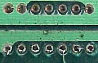
|
|
The "Hard" way: here the desoldered chip is lifted from the board with a small screwdriver (and the screwdriver could break a trace doing this!). The problem here is the solder pads LOOK free of solder. But the pins of the chip are attached to the sides of the plated-through circuit board holes. This means as the chip is lifted, it takes the circuit board trace(s) with it! Note the second pin from the bottom; can you see how the solder pad and trace has lifted from the board? |
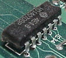
|
-
Plated-Through Holes (PTH) Warning.
Plated through holes are how a circuit board trace gets from one side (of a double sided circuit board), to the other side. They are also used for component soldering. When a component (chip, resistor, cap, etc) is soldered into a PTH, solder files the hole and surrounds/attaches to the part's leg. This makes an incredible bound. If the part is desoldered improperely this bound will still exist to at least some extent. When the user removes the part, the part's leg comes out but the PTH stays attached to the part leg, and is ripped from the board. Now the conductivity from one side of the board to the other side is questionable, even when a new part (or socket) is installed.
Desoldering the "EASY" way.
Because of the danger of ruining plated-thru holes, often
the best approach to desoldering is to simply cut the old part
from the circuit board, and then desolder it. In the case of an old
chip, the body of the chip is cut away. Then each leg can be heated
with a soldering iron and removed with needle nose pliers. Then the
solder can be desoldered from the hole easier and without risk of
damage to the plated-through hole. This may not always
be easy to do this (like when replacing an old socket), but it really is
the best way for a newbie to desolder, with the least risk of damage.
Note there are some times when you don't want to cut the old part out. For example, if the old chip is needed for some reason, or it is a component that just can't be cut out. But in most cases, a component is being replaced, so if damaged, it is no big deal. Remember, it's the circuit board that you don't want to damage. Cutting out a part that is being replaced anyway is just the cost of repair. Chips are cheap, circuit boards are not.
What to use to Cut off the Old Component.
Buy a good set of wire cutters to cut the old components off
the board. Get the "flush cut" variety rather than the
traditional "dikes" or "diagonal cutters". The traditional style
dikes just won't cut close enough to the board.
Though Radio Shack isn't the best place to buy
component cutters, part numbers 64-1833 or 64-2043 or 64-2044 will work.
Also MCM sells a Xcelite micro series shearcutter for $5, part number 22-1050.
Whatever cutters are purchased, it's best to use a pair with long narrow (needle nose)
cutting edges, to get between chip legs for easy cutting.
Try and keep the legs of the chip
as long as possible when cutting.
You want to leave as much of the component's legs
sticking out of the board as possible.
Another method to cut a chip out is with a Dremel tool and a Dremel cut-off disc. This works great, but is not recommended, especially for the newbie, as a slip of the Dremel could cut traces on the circuit board. Better to use a "flush cutter".
|
The chip after it has been cut off the board with a Dremel. Note the length of the legs sticking out of the board. The Dremel is not the best way to cut out a chip, but it does work. A better choice is to use a Flush Cutter. |
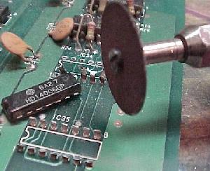
A 4.5" flush cutter. |
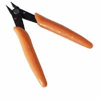
-
Removing the Left-Behind Component Legs.
Now that the chip body is out of the way, remove the chip's cut legs, one at a time. Using a soldering iron, heat each cut leg of the chip, and remove it with a needle nose pliers. If a Hemostat (used largely in the medical fields) is available, these work really well for this task too.
|
Removing each individual cut chip pin with a soldering iron and needle nose pliers. |
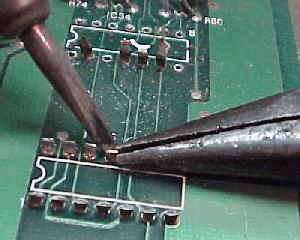
|
-
Cleaning out the Old Solder from the Holes.
After all the pins are removed, use your favorite desoldering tool to clean out the old solder from the solder pads. See the tips below on using a particular desoldering tool.
|
The removed chip's solder pads after desoldering, when you do it the easy way! |
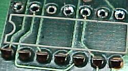
|
-
Install Machine Pin Sockets or Dual Wipe Sockets.
"Machine pin strip sockets", also known as SIP sockets (Single Inline Package), are a good choice for repairs. Buy them in the longest length possible, and just cut them to the length needed. This way, there is no need to keep specific sized sockets around (just cut them to the length needed). The reason many repair people like them is the ability to see completely around the traces, AFTER they are installed in the board. If by chance a circuit board trace is broken, it can be found much easier.
Another reason many novice repair people like machine pin sockets is the ability to soldered on the TOP side of the circuit board too (though this is not suggested, and should only be done if absolutely needed). If the "plated through hole", which the socket pin goes through, cracks or becomes damaged, the socket may need to be soldered on both sides of the circuit board to maintain continuity from the solder to component side of the board.
Note soldering on the top side of a machine pin socket is only a last resort when there is no continuity between the two sides of a circuit board. Top side soldering can lead to a variety of problems such as increasing the risk of shorts between socket legs, heat damage to the circuit board, and its virtually impossible remove flux because the sockets is in the way. Also machine pin sockets are not designed to be soldered in this manner (often melted socket plastic can be seen where someone has tried to get the soldering iron tip close to the socket pins).
"Dual wipe" plastic sockets are also excellent sockets to use. If the old part was properely desoldered without damage to the plated-through holes, dual wipe sockets are more than acceptable for repair. The important part here is the "dual wipe" part. That is, the inserted chip has metal wipers on both sides of the chip leg. Quality plastic sockets uses dual wipers. This is the only variety of plastic socket that should be used.
Is there any advantages of dual wipe plastic sockets over machine pin sockets? Machine pin sockets hold the chip better, and that's why the military requires their use. But for pinball applications dual wipe plastic sockets are excellent, and there is less risk of chip damage when inserting a chip. Machine pin sockets have a much higher incident of bent "accordian" chip legs upon insertion.
Machine pin strip sockets are available from Mouser at www.mouser.com (800-346-6873). They sell a variety of lengths, and can beut to any length needed. Shorter strips may also be combined into one long single strip too. I personally try and get the most length for the dollar. For example, 32 pin tin exterior and gold interior plating, part number 575-193132 is $0.93. Going much longer than that, and the price really jumps. Another source of this is KCC (Keltron) Connector Corporation in Bohemia, NY (800-346-3532) at www.connectworld.net/keltron/kelt21.html. They have SIP sockets available with standard leads, selective gold plating, and 100 contacts for about $1 each. But you'll need to buy 100 of them at a time, as they don't sell in any smaller quanities.
|
Machine pin socket strips. Note the great access to the solder pads, and nothing is hidden by the socket itself. |
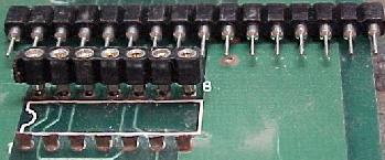
|
|
If not using machine pin sockets, be aware there are different quality plastic sockets. The socket on the left is what I would call "average" quality. The socket on the right is "excellent" quality. Notice how the socket on the right has metal tensioners/contacts on both sides of the chip's pins (opposed to just one side). This socket has "dual wipe" contacts with wide entry areas, for easy component insertion and great conductivity. |
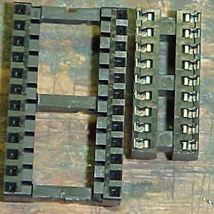
|
-
Plated Through Holes Again (and Soldering on Both Sides of the Board).
Most pinball circuit boards are "double sided". This means they have traces on both sides of the board. If a trace needs to go from one side of the board to the other, a "plated through hole" (PTH) is used. When the board was constructed, a hole was drilled in the board, and metal plated on the INSIDE of the hole. This way a trace on the top side of the board can continue to the backside of the board, through this hole. If a component doesn't go through the hole, plated through holes are soldered closed to help maintain their electrical continuity.
The problem with plated through holes is they are easy to "strip out" or crack when desoldering. If a component is difficult to desolder, sometimes the plating inside the hole will delaminate, and pull out with the old component. This means the ONLY connection between the traces on either side of the board is the component going through the hole! If the component isn't soldered on BOTH sides of the circuit board, there may not be continuity between the two traces.
Again the reason machine pin sockets are desirable is their ability to be soldered on both sides of the circuit board. Though not suggested (and really a "hack"), machine pin sockets can be top-soldered if needed. But remember the warnings mentioned above - top side soldering is not suggested and should only be done if absolutely needed.
|
Here are the two styles of replacement sockets. The SIP style of machine pin sockets are ideal. They also allow full access to the circuit board on the component side, in case of a bad trace. |
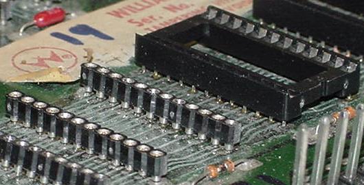
|
- First examine how the chip or part is attached on the solder side of the circuit board. Often manufacturers will bend-over pins before soldering. If these pins are not straightened *before* desoldering, they will not desolder cleanly! This risks damaging plated-thru holes as the part is removed, tearing out the PTH. If the part leg is bent over, heat its solder joint and use a pointy non-metalic object (a wood dowel) to straighten the leg. Only after the leg is straight can it be properely desoldered from the hole.
- If a solder pad just won't desolder cleanly, resolder it first! That's right, as dumb as that might sound, it works great. Use the soldering iron and add some new solder to the joint. Then there is plenty of solder present to heat up the entire solder joint and distribute the heat. This makes desoldering much easier.
- If the component leg to be desoldered is round, rotate the desoldering tool in a small circle to get all the solder from around the component leg. Note this is nearly impossible to do with a "Soldapullt", but can easily be done with a decent vacuum desoldering station.
- If the component leg to be desoldered is flat, laterially move the desoldering tool to get all the solder from around the component leg. Note this is nearly impossible to do with a "Soldapullt", but can easily be done with a decent vacuum desoldering station.
- Do not apply too much heat when desoldering! Remember excessive heat will lift circuit board traces, and can ruin a circuit board. If it's taking lots of time/heat to desolder a joint, you are doing something wrong!
- Think about using some method to hold the circuit board in place while you desolder. There are special rubber jawed mini vices for this task.
General Desoldering Tool Tips.
No matter what desoldering tool used, here are some
general desoldering tips.
|
Round versus flat component leg desoldering, and how the desoldering tool should be moved during desoldering. Note this is nearly impossible to do with a "Soldapullt", but can easily be done with a decent vacuum desoldering station. Pictures thanks to www.ipc.org. |
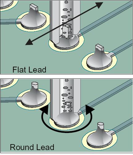
|
|
Straighening a bent-over componenet lead before desoldering. Picture thanks to www.ipc.org. |
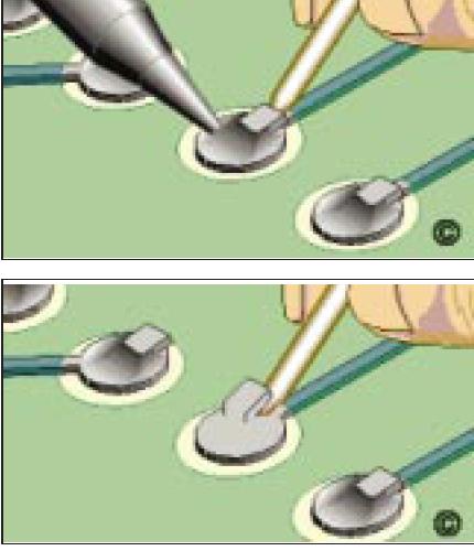
|
-
Using a "Soldapullt" Desoldering tool.
For first time repair people, the Soldapullt tool and a *temperature controlled* soldering station is the best tool to start with. This way the amount of heat applied can be controlled.
The syringe like vacuum Soldapullt tool requires using a soldering station too. In one hand have the soldering iron, and in the other hand have the "cocked" Soldapullt tool. First heat up the solder joint to desolder with the soldering iron. Then put the Soldapullt over the joint at an angle (trying not to touch the soldering iron's tip). Now move the soldering iron away, and quickly position the Soldapullt perpendictular to the board, and quickly press the trigger. This should suck the molten solder from the joint.
|
Heating the joint with a temperature controlled soldering iron, with the Solderpult in place and ready. |
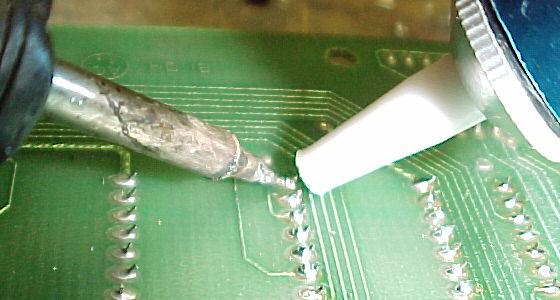
|
|
As soon as the solder is melted, the iron is pulled away, and the Solderpult's tip goes over the joint and is angled perpendicular to the circuit board. Then the button is pressed on the Solderpult, and the molten solder is removed. |
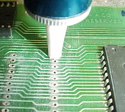
|
Try not to put the Soldapullt tool tip right on the soldering iron's tip. This is not always possible if you're in tight quarters, but practice helps. For instance if desoldering a lead on the underside of a board, put the tool right next to the lead you're heating, but not touching it. Then in one motion pull the iron away and put the Soldapullt straight over it and hit the trigger. It's tempting (and easier) to just do that without pulling the iron away. That will eventually wear the Soldapullt's tip. It's up to you whether to learn the technique or just feed new tips to the Soldapullt over time.
The absolute best technique for removing IC's is to heat against the IC leg on TOP of the board, while holding the Soldapullt against that lead on the BOTTOM of the board. Gently pushing on the IC leg with the soldering iron to center it in the hole while "sucking" is worth bonus points. Then when the Soldapullt's trigger is pressed, it will usually suck all of the solder out cleanly (normal cautions about not overheating an IC leg or circuit pad apply here.)
Note: If a lead is being stubborn, or if your first attempt didn't get all the solder out, here's a tip. Resolder the lead with the soldering iron and some solder. This will give the iron more solder to heat, and the Soldapullt more stuff to pull on when sucking it out. Often, on really fragile or older circuit boards, I will just resolder all the points I am about to desolder, before even attempting to use the Soldapult.
After done "sucking" a solder joint, cocking the Soldapullt blows most of the old solder back out. It is a good idea to open the tool up from time to time and dump out the bits and pieces that hang out in there. Plus, a cake of solder tends to build up on the face of the piston; peel that off too.
Desoldering Stations: Do NOT Use Until it's HOT.
Don't be impatient when using a desoldering station. Let is warm
up fully before using it. If the desoldering station is used before
it is hot, this will almost guarentee that the tip and connecting
"Y" adaptor will clog!
Desoldering Station Maintainence.
Desoldering stations all require maintainence to work correctly.
All have some sort of solder collection tube, which must be
emptied often (at least once per usage session).
This should only be done when the desoldering iron
is HOT. The same applies to tip changing; only change a tip when
the desoldering tip is hot. If tip removal is attempted when the iron is
cold, it is almost guarenteed to break the tool, as the tip
is "soldered" to the connecting "Y" adaptor.
All desoldering stations also use some sort of filter to keep the old solder from getting into the air source (this filter is usually located in the solder collection tube). The filter could be as simple as a (100%) cotton ball (do NOT use synthetic cotton, as it will melt!) Be prepared to replace this filter every now and then. Another replacement item is the rubber gasket that seals the solder collection tube to the "Y" adaptor. With time these dry out and fall apart. So it's not a bad idea to have a few of these rubber gaskets around too.
Also many desoldering stations also offer a declogging "toolkit" that includes a set of miniature round files. These are used to clear the desoldering tip and adjacent "Y" adaptor of any stuck solder. It's a good idea to have one of these toolkits too, if it didn't come with the new desoldering station.
Using Desoldering Braid.
Desoldering braid is flexible copper braid with impregnated flux.
Always use "fresh" solder braid. The stuff has a shelf life;
the flux can dry and fall out, causing the braid to oxidize and become useless.
To use it, just take a small length of braid, and put it right over the solder joint you want to desolder. Then put a hot and tinned soldering iron on the braid. The braid will heat up, and melt the solder joint below it. The molten solder will be "absorbed" by the braid, leaving the solder pad clean and clear. Do not reuse this section of solder braid; always use a new fresh section for the next solder joint to desolder. Cut the old section off about a 1/4 inch from the absorbed solder (the flux probably melted out of the braid any closer).
Desoldering braid works well, but it requires additional heat to make it work (your soldering iron needs to be hot!) Excessive heat is bad for a circuit board, as it can cause the solder pads and traces to lift from the board. Also adjacent electrical components can be damaged from the heat.
|
Using the Radio Shack desoldering iron. |
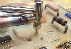
|
-
Using the Radio Shack Desoldering Iron.
- Let the desoldering iron warm up for at least 10 minutes.
- Before putting the hollow tip of the hot desoldering iron over the solder pad to desolder, Compress the red bulb with the same hand that is holding the desoldering iron.
- Put the hollow tip over the pad to desolder.
- Let the existing solder melt for a second, then quickly let go of the red bulb.
- The solder should be sucked out of the board and into the desoldering iron.
- Remove the desoldering iron from the solder pad.
- Clean the old solder out of the desoldering iron by compressing the red bulb a couple times. Point the tip AWAY from anybody when doing this!
- Make sure the desoldering tip is not worn out. Typically the tip on these ENLARGES, decreasing the suction on a solder joint. When replacing the tip ALWAYS buy the "iron clad" version (part number 64-2062, $1.99), as it lasts much longer.
Because this device is essentially a 45 watt iron, I don't recommend it for the first time repair person. But it is an easy desoldering tool to use. Here are some tips:
3h. How to Use It: Summary of Tool source and part numbers.
These are the various models and sources for the above mentioned tools. I list them in my personal order of perference with the best usability per dollar items listed first.
Lighting
- Magnifying work lamp, built in circular florescent lamp, part number 21-935, about $50 ($40 on sale). MCM electronics.
- Magnifying work lamp, built in standard incandescent, part number 22-3995, about $25. MCM Electronics.
- Magna-Lites lighted reader, 4x power, part number 21-6595, $6.99. MCM Electronics.
Soldering Tools
- Tenma's soldering station, LED temperature display, part number 21-147, $80 ($60 on sale). MCM Electronics.
- Tenma's soldering station, digital temperature display, part number 21-1590, $120 ($80 on sale). MCM Electronics.
- Replacement soldering tips for above Tenma soldering stations, screwdriver style, part number 21-926 (1/6" wide) and 21-927 (3/64" wide) for $2.49 each. MCM Electronics.
- Replacement grounded iron elements for above, part number 21-151 for $11.50. MCM Electronics.
- SPC Technology digital display station (digital temperature control), part number 21-6690, $89.95. MCM Electronics.
- Weller WES50 soldering station, about $110, part number 96-1340. MCM Electronics.
- Hardcase dual heat soldering station (20/40 watts), $29.95, part number 21-6050 (sometimes on sale for $17.95). MCM Electronics.
- Replacement tips for above, part number 21-6055. MCM Electronics.
- Weller SP23 soldering iron, about $12. Home Base or Home Depot.
Solder
- Kester "44" rosin core 60/40 solder, .031", one pound, part number 21-1840, $12.75. MCM Electronics.
- Kester "44" rosin core 60/40 solder, .040", one pound, part number 21-1830, $12.75. MCM Electronics.
- Radio Shack rosin core 60/40 solder, .032", 8 oz, part number 64-009, $7.99. Radio Shack.
- Radio Shack rosin core 60/40 solder, .032", 2.5 oz, part number 64-005, $3.79. Radio Shack.
Desoldering Tools
- Mini Soldapullt tool, part number 64-2098, $6.99, Radio Shack.
- Low-static Soldapullt, part number 21-4700, $9.99. MCM Electronics.
- Anti-static generic Soldapullt, part number 21-590, $6.99. MCM Electronics.
- Desolding Braid. Radio Shack part number 64-2090 $2.79, or MCM Electronics part number 21-1005, $2.59.
- Desoldering iron, part number 64-2060, $9.99, Radio Shack.
- "Iron clad" desoldering tip for above, part number 64-2062, $1.99, Radio Shack.
- Tenma desoldering station, part number 72-6340, about $300 ($250 on sale). MCM Electronics.
- XYtronics desoldering gun, part number 129066, about $100. Available from Jameco Electronics, http://www.jameco.com/cfm/viewdesc.cfm?part_num=129066
- XYtronics desoldering station, part number 125508, about $300. Available from Jameco Electronics, http://www.jameco.com/cfm/viewdesc.cfm?part_num=125508
- Den-On SC7000Z desoldering gun, $399, Howard Electronics.
Digital Multi-Meters (DMM)
- Tenma 72-4325 DMM, manual ranging, $70, MCM Electronics.
- Triplett Corporation's model 9010 DMM, autoranging, $50, part number 74-217. MCM Electronics.
- Tenma #72-2055 DMM, manual ranging, $32, MCM Electronics.
Logic Probes
- Logic probe part number 22-303, $17.99, Radio Shack.
- The Wittig Technologies osziFOX Probe style oscilloscope logic probe, available from Radio Shack for $79.99 (1-800-The-Shack, catalog# 910-4905, RSU# 11910486,). Also available from Test Equipment Depot (1-800-517-8431) for $ 69.00, or directly from the manufacturer at wittig-technologies.com.
Misc.
- Machine Pin Sockets, cut to desired length, 30 pins, part number 21-299, $0.49 each. Hosfelt.
- Chip Tester, part number LBT-10 (Lil Bitty Tester), $200, MCM Electronics. Made by Lil' Bitty Tester Inc., San Diego, CA92105, (619) 284-0210. Interestingly, they don't have a company web page!
- Resistor Color code decoder, part number 271-1210, $1.19. Radio Shack.
- ECG or NTE Semi-conductor master replacement guide.
- Tenma Capacitance meter, part number 72-040A, $70. MCM Electronics.
Source companies:
- MCM Electronics, http://www.mcminone.com, 800-543-4330.
- Radio Shack, http://www.radioshack.com, local stores through out North America.
- Jameco Electronics, http://www.jameco.com, 800-831-4242.
- Hosfelt Electronics, http://www.hosfelt.com, 800-524-6464.
- Howard Electronics, http://www.heinc.com/den-on/sc7000.html, 800-394-1984.
End of Beginning Circuit Board repair document.
* Go to the Pin Fix-It Index