Straightening a Warped United Bowling Alley Lane.
10/11/06, by Duncan Brown and cfh@provide.net

    This procedure was used on a 1958 United Bonus bowling alley and a 1960 United Bowlarama. It would probably apply to most other United ball bowlers. Note CCM ball bowlers don't have this problem as their lane attachment method is completely different (and better).

    Before starting, note a couple things about United ball bowlers. First the lane deck does NOT sit flush with the gutters. The gutters are part of the overall frame of the lane, while the deck "floats" above it on rubber cushions, to minimize noise. So there is maybe a quarter inch height difference between the top of the lane deck, and the gutters slightly below it. When the deck warps, large sections of it can sink down to the gutter level, which is what confuses people into thinking the lane should be flush with the gutters.

    On the 13 foot Bonus bowler, the frame has two pieces - a 6 foot front frame (with the coin mech, etc) and a 5 foot rear frame (with the pin unit, etc). The deck has three pieces - a 6 foot front part (exactly matches the front part of the frame), a 2.5 foot middle part, and a 2.5 foot switch part that sits under the pins (the two 2.5 foot parts are mounted on the rear 5 foot frame).

    On the Bowlarama (a 20 foot monster), the frame has three pieces - a 10 foot front frame (with the coin mech), a 5 foot middle frame, and a 5 foot rear frame that houses the pin set unit and the lane switches. The deck is similar to the Bonus, and is three pieces (10 foot, 6 foot middle, and a 3 foot switch deck). Now my Bowlarama was slightly modified. Originally there were just two frames (the current middle frame was permanently attached to the rear frame, making the game have two 10 foot frames). But a previous owner modified the unit to be three frames (one 10 foot frame by the coin box, one 5 foot frame in the middle, and another 5 foot frame under the pin set unit), making the 20 foot monster considerably easier to move.

    On both the Bowlarama and the Bonus, the frame pieces fit together at the middle seam via a tab/slot arrangement in the gutter sections. There are four (about 2 feet long) bolts (two under the gutters, two at the edges of the deck area) that pull it together tightly, through metal braces. There is an electrical connector at the joint in the right side gutter (ball return side.) Normally when disassembling the alley for transport, you would remove the 4 bolts but leave all the deck sections attached to the frame. If they can stay put, warping and straightening of the decks is less of an issue. But in practicality, removing the decks would be nice. Removing the deck sections makes assemblying, moving, and re-assemblying the bolwer *much* easier and lighter to move. So there is some need to make the decks removable and reattachable in a durable manner. On both of these ball bowler the decks were quite warpped.

Here's the connection between the lane frames on the Bowlarama. Two of the four long bolts can be seen.
Also shown are the metal tube and the rubber pucks for securing the deck to the frame.
The gap between the two cross braces is where the warped "ski jump" in the two lane decks occurs.
Note the rubber pieces - the thicker black pieces go on top and sandwich between the frame
and the plywood/formica lane. The thinner red rubber go underneath the frame. The red
and black pieces are connected with a piece of brass tubing. The lane attachment wood screws
go through the brass tubing. Note I replaced these lane attachment wood screws with threaded
machine screws (see below for details on how that is done).

Here one of the 2 foot long lane frame bolts can be seen holding the two lane frames together.
Also the deck screw rubber disks and fender washer is shown.
Note a 2" wide oak (or maple) cross brace can be added (blue arrows) at the edge of each
part of the frame for additional areas to attach the lane plywood and to minimize lane warpage.

The decks are made of 1/2" plywood with a thin Formica lane veneer laminated on the top. On the bottom side of the decks is some sound deadening material. The rearmost deck piece has lots of slots in it for the switches (more slots on the Bonus than the Bowlarama), so United was worried about it warping. They added oak braces underneath and made sure there was room for the braces in the area of the frame below. These kept that deck section quite straight (well it did once I tightened the screws again - all the screws had loosened due to the moisture cycling in a basement environment). Both the Bowlarama and the Bonus did not have any problems with this deck section. The very rear edge of the rear deck section simply tucks into a slot at the very back of the frame, while the front edge is screwed down to a cross brace with three counter-sunk screws.

The middle deck piece is secured at its rear edge (butted against the rearmost deck piece) with three more countersunk screws, into that same cross brace. A third of the way back from its front edge, it is spaced off of another cross brace by two thick rubber disks, with tubes and screws run through them from the bottom of the cross brace, up into the deck itself. A large fender washer and two smaller washers are used at each screw head, along with the brass tube, to keep the screws from being overdriven to the point they would pop out of the top of the lane deck (all THREE washers are required!) The front edge is screwed to a separate plate that I will describe later. The majority of the underside of this deck section is covered with stapled-on tackboard, used for sound deadening.

Here's the underside of the Deck, showing the sound deadening material below the
gray painted 1/2" plywood bottom. The large round holes in the tackboard are for
the lane attachment rubber washers and screws.

The gray painted plywood bottom is delaminating here.
Also the stapled sounds deadening material is easily seen.

The frontmost deck piece also screws to a plate (described later) at its rear edge, where it butts against the middle 
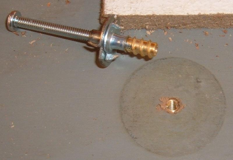
deck piece. It then floats above the frame on rubber disks - two or three at a mid cross member, and two or three at the cross member at the very front of the whole alley (Bowlarama uses three per row, Bonus only two per row). 
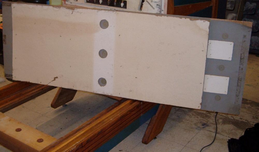
It is similarly covered with stapled-on tackboard on the bottom (in two sections) for sound deadening. At its rearmost lip, where it screws to that plate, there was a thin strip of rubber. I am convinced that is there to guarantee that the back of the front section sits ever so slightly higher than the front of the middle section, to make sure the ball hops DOWN as it crosses that gap, rather than strking the front edge of the middle section and cracking the formica, affecting ball travel, etc. So in that sense, there is the tiniest bit of lane warp built into the design!
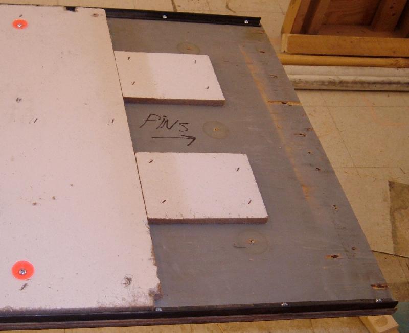
About this plate; it spans across the gap between the front and middle lane section by a few inches on each side, and spans side to side as far as it can without fouling on the bolts that hold the frame together. So in other words, both deck section bolt down to it in the middle, but not on the outside few inches on either side (which allowed the deck sections to "dish" from side to side, in addition to the front-back warp.) It is made out of layered hardwood so that it forms a perfectly flat, stiff plane for the deck sections to mate to, guaranteeing alignment and reducing warping (except at the edges, as I mentioned.)

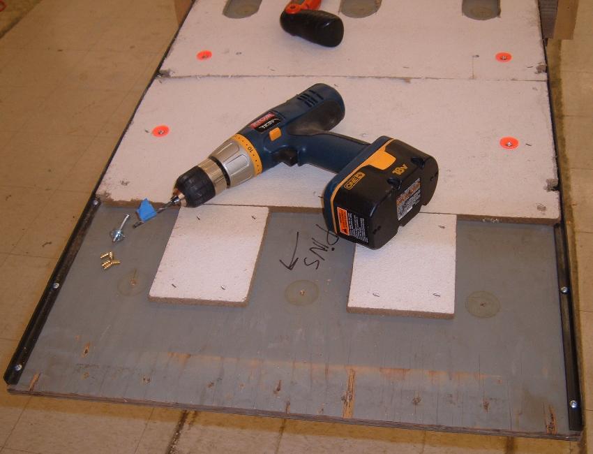
Adding a new Lane Frame Cross Member.
When I put it back together, I used a 2"x6" piece of solid oak or maple, the width of the lane deck (a little over 17 inches)...then drilled countersunk holes into it and used very coarse thread square-drive screws to pull the deck sections down against it tightly. Because it was as wide as the deck, it was in the way of the bolts, so I drilled holes through it edgewise, front to back, to allow the bolts to pass through. (They sat exactly on center with the thickness of the board, thank goodness!) I drilled them oversize to allow the bolts to float around inside the hole and not make contact anywhere (because that would transmit vibration and noise.) Did I really need to do that? I'm not sure - my other de-warping strategy actually worked amazingly well, and the original narrower plate might have actually been able to do the job at that point. (I kept it, and might just reinstall it to find out, next time the alley is disassembled for transport.)

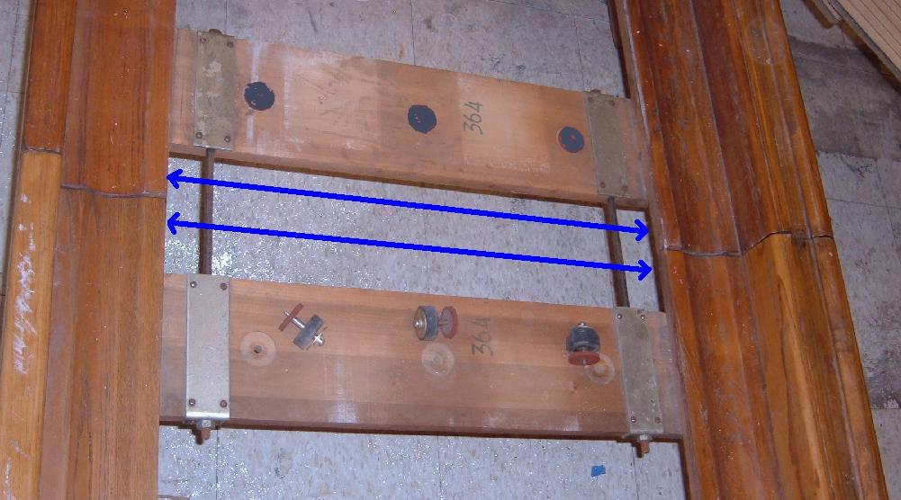
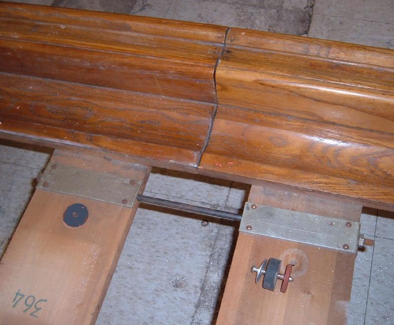
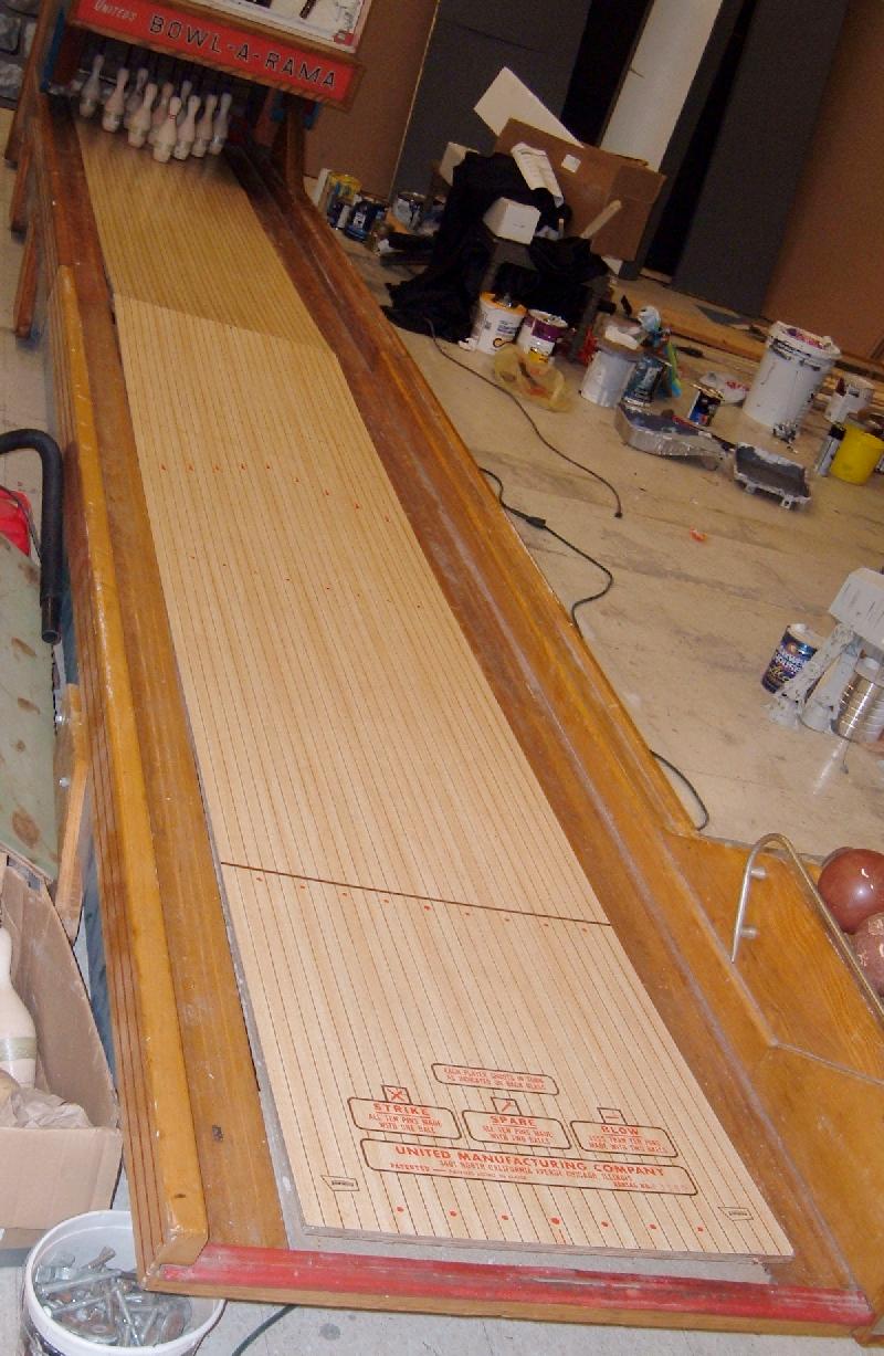
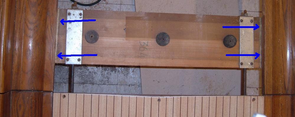
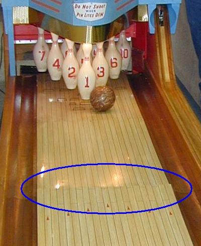
The "before" picture. The blue circle shows the lane warp
and the ski jump it created.

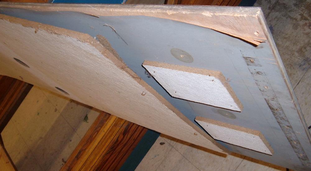
    Adding Angle Iron to the Lanes.
    Now for the main dewarping strategy. Like I said, the rearmost piece was actually quite flat since I retightened the screws on its oak braces. But the middle and front sections looked like swayback horses! To fix this, I purchased some 1/2"x1/2" by 1/8" thick heavy angle iron (they call it "weldable iron" and it's pretty heavy stuff). I got four 4' lengths, but Home Depot sells 3' lengths (which you can use, but 4' lengths would be more desirable). Along one face of each length, I drilled 11/64" holes every few inches, which will accomodate #8 by 1/2" long screws. For the front deck section, I used one 4' section on each side, placed front to back in such a way as to miss most of the cross braces. For the middle deck section, I cut them down to go the length of the section except for where my new oak plate went at the middle seam. Starting at one end, and butting them up against the tackboard insulation on the bottom of the deck sections, I firmly installed a #8 by 1/2" long screw into each hole, using coarse-thread screws that were not long enough to poke through the top of the formica deck. I alternated each side's bracket, too. So basically I was little by little pulling the deck up straight against the angle iron as I went. It's not perfect, but it definitely got it within a hair's breadth of being flat front to back.

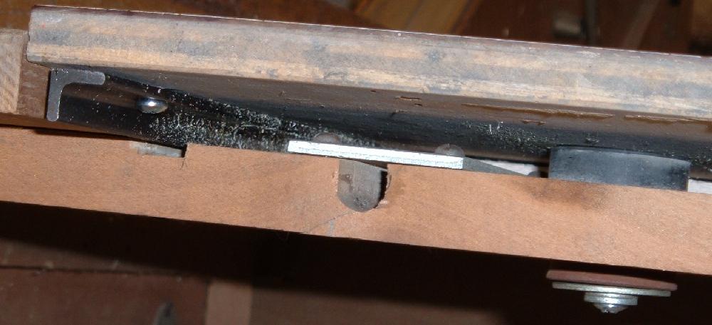
    Ah, but there's a problem - the 1/2" side to the angle iron is greater than the distance that the deck sections sit off of the cross braces!! Not only do they not make angle iron any smaller, but any smaller wouldn't have been strong enough to pull the warped wood straight. So I (brace yourself) NOTCHED the cross braces to allow room using a router with a 3/8" bit. I cut two 1/4" deep 3/8" wide slots centered on where each angle iron was making contact and then routed the wood out between the slots. This is one each side, on two cross braces (total of 4 routed slots in this otherwise pristine 1958 woodrail bowling alley). But it's all hidden when the thing is assembled. A router worked great (the slots are next to the gutters) to make clean looking slots.

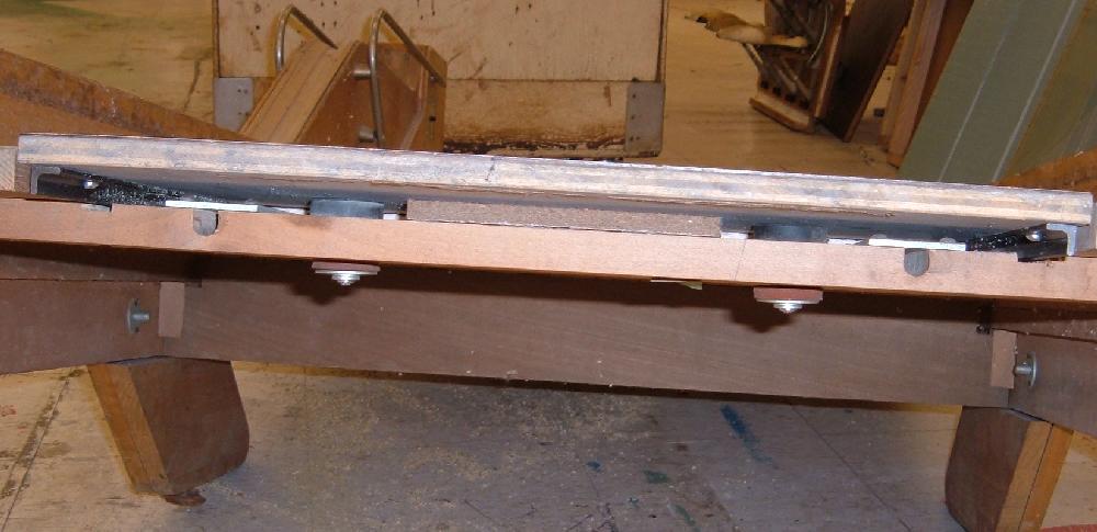
    With those slots now allowing clearance for how far the angle iron hung under the alley, I put everything back together, and cinched it down tight. Nice, nearly-flat alley decks, with the slight built-in lip at the middle seam. Perfect!

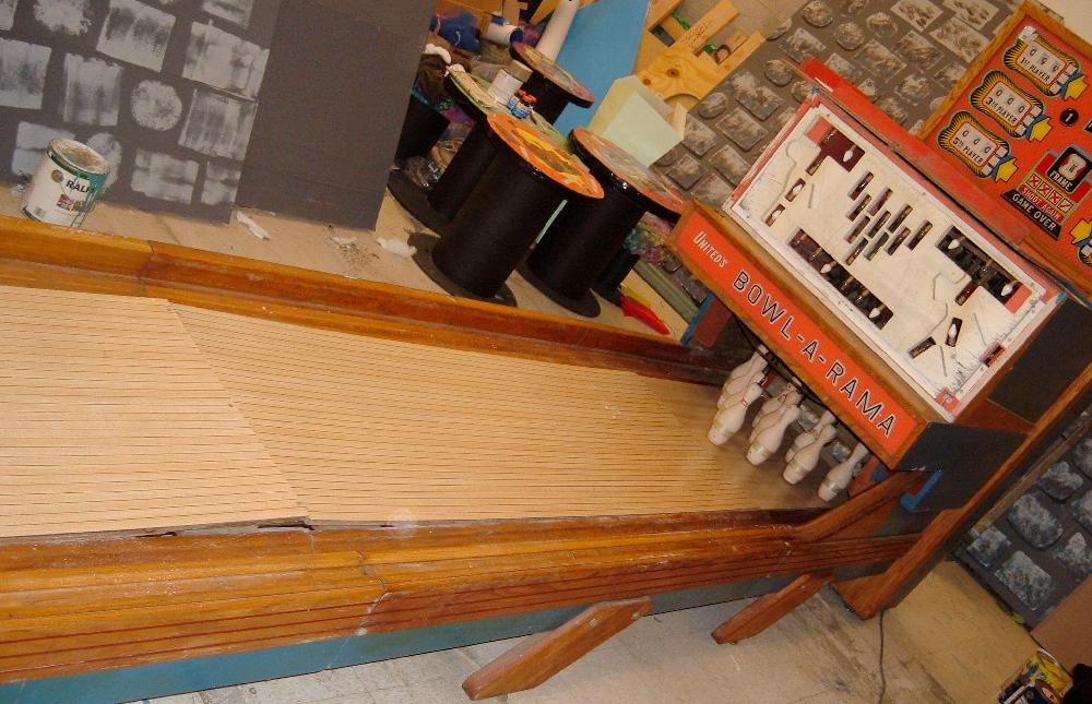
    The "before" picture was taken before I did this procedure. In that picture, the deck sections have just been layed back down in the frame and you can see how badly they are warped - notice the lip at the center seam!

Here's the Bowlarama deck not bolted down. The warp is obvious.

Here's the brass inserts which I installed into the lane plywood. This replaced the wood screws which go thru the brass tubing and rubber washers, mounting from underneath the lane frames and into the lane plywood, and hold the formica/plywood lane to the lane frame. With the brass inserts I could use 8-32 or 10-24 machine screws into these brass inserts to hold the lane plywood/formica to the lane frame. This was much more secure and re-attachable, as the wood was torn up from the wood screws, and would no longer securely hold the lane plywood/formica to the lane frame. Since the brass inserts are somewhat soft, I used this double T-nut arrangement to install the brass inserts into the plywood (otherwise the brass inserts were easily damaged). The new machines screws are two inches long.

Here's 1/2" by 4 foot long angle iron was added to the lane sections to help remove the warp. These were attached underneath the plywood/formica lane sections with multiple wood screws.

The sections of the lane frame needed to be notched (routed) slightly to accomodate the angle iron into the lane frame (blue arrows).

Here's the part of the lane closest to the player, which butts up to the other lane section. In these two pictures the angle iron, slot route, and new machine screws (which go thru the rubber discs) are all shown.