06/15/07. By cfh@provide.net
This information applies to all 1990s Capcom pinball games.
This document is a "work in progress", and is not complete.
Capcom "Classic" Boardset.
In Breakshot, which was intended to be a lower cost, simplified pinball
machine, Capcom used their "classic" boardset. This was different from
the other boardsets in other Capcom pinballs in a couple ways.
First the power supply, driver board and switch matrix board were a single board
(in the other systems, the power supply was the upper-most discrete board,
with the driver board below it, and the switch matrix board below that).
The switch matrix on the "classic" boardset was not buffered either,
unlike the more expensive discrete board system.
Also the sound board used just one custom square sound chip instead of two (but
two could be installed, just the second sound chip was not used).
The CPU board (mounted behind the dot matrix display) was the same on
all Capcom pinballs. The lamp power board (to the left of the CPU board)
is also the same on all Capcom pinballs.
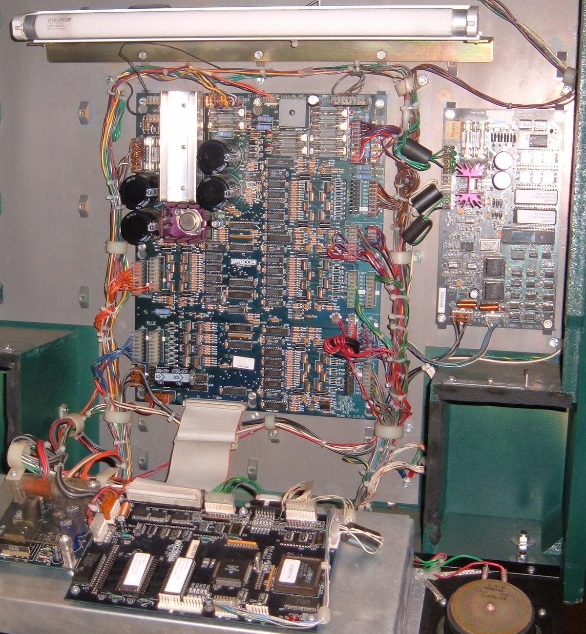
The Capcom "classic" boardset in a Breakshot.
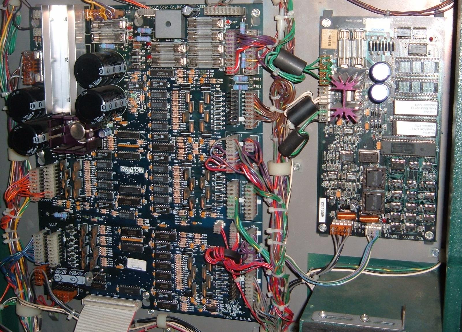
A close-up of the Capcom "classic" power supply/driver board/switch matrix board,
and the sound board at the right.
Game Resets.
A common problem with all flavors of Capcom pinballs are game
resets. This happens because the larger filter capacitors mounted
on the power supply board vibrate and crack their solder joints
(and often the plated-thru holes), giving intermittent connections.
Also the bridge rectifiers can develop cold solder joints too.
Power Supply Cap Problem - Game Will Not Boot.
First thing to check is the six (or four on a Capcom "Classic" boardset)
TALL electrolytic capacitors on the power supply
board. They are just too tall to be mounted on a vertically mounted PCB!
They weigh too much and develop bad connections (cracked solder joints) in the
long run. Note Williams used shorter, fatter caps to prevent this problem.
Resoldering these caps will fix many games that just will not turn on.
But the real solution is to install shorter capacitors (if they
will fit in the physical space).
Switch Matrix Reliability Problems.
Capcom had the great idea of not mounting a diode on each
playfield switch. Instead, the diodes were mounted on a long
skinny switch matrix board in the back box. This made switch
replacement easier for the operator.
In the case of all the other pinball manufacturers, they would run a single switch Row and Column wire to a playfield switch, and then daisy chain the rows and columns to each switch. Also each switch had its own diode. Also there was but one connector for the eight switch row, and one connector for the eight switch columns.
But in the case of Capcom, since each switch's diode was remotely mounted on the switch matrix board in the backbox, a two separate wires were needed for each of the 64 switches! This meant instead of two 8 pin connectors (16 wires total), on Capcom games there are 64 wires (plus ground wires). And of course this means there are way more connectors for these additional wire (all are the smaller .100 style connectors too). More connectors are bad, as reliability suffers (most Capcom connectors are the IDC type).
Capcom also uses SIP style resistor networks on the switch matrix board. As we learned from Williams' System11 games, this style of resistor often fails too. Make sure to check these. Individual components would have been nice, but take more physical space on the circuit board.
The switch matrix board also has another problem, the use of surface mount LM339 chips.
Surface mount chips makes the switch matrix board much smaller and cheaper to manufacturer. But surface mount in pinball is strickly a no-no. The problem is vibration. Eventually the switch matrix LM339 chips start to delaminate from the board, giving reliability problems.
The LM339 chips that are most problematic are the ones towards the edges of the switch matrix board. These are the ones that delaminate first. By "delaminate", I mean the solder cracks that holds the chips to the board (the chips don't actually fall off the board!) This makes the chips intermittent (or at worst, not work at all).
"Regular" pinball circuit boards use double-sided, plated-thru holes. This means the chips actually go through the board, and are soldered on both sides of the board (because capilary action sucks the solder through the circuit board's plated-thru holes). This is a much better design as the chips are held to the board with a better physical connection. Single side boards and surface mount boards don't have the same good physical bond, and will have reliability problems with age.
So what we have here is a switch matrix nightmare. And there is no easy way out of this. Oh and did I mention that the switch board is mounted very low in the head, making switch diagnostics very difficult!
In my situation (Pinball Magic), I had two (of the eight) switch connectors on my switch board that did not work. I knew it is a problem on the switch board; if I moved these connectors to another of the working switch connectors, the playfield switches worked fine! I had tested the SIP resistors (found one bad), so that's fixable. But now I had a problem with one (or maybe as many as four) of the LM339 surface mount chips.
Some other Capcom games I had also had the switch problem, most of the time, it's the two (or four!) LM339's on the left hand side . You'll find that the LM339 aren't really bad, but if you press them down gently with a screwdriver they'll make contact!! I've repaired a couple with a very thin, very light solder station by gently holding it very briefly to the unsoldered pins so they make contact again.
Diagnosing/Fixing the Switch Matrix.
My problem was the switch connectors J1 and J2 and all their switches
just did not work. I used a logic problem on the switch board connectors,
and they seemed to be working! But really the surface mount LM339 chips
had delaminated, as suggested above.
To test that the playfield was not at fault, I removed the plastic "keys" from the playfield plugs J1 and J2 going to the switch board. Then I plugged these connectors into the (working) switch board connector J3. All the playfield switches connected to either J1 or J2 now worked! (except for the one switch that plugged into the "key" pin on connector J3). So I knew the problem was not on the playfield.
Next I removed the switch board and put it on the bench. I then resoldered all the pins on one side of the first left-most LM339 surface mount chip. I was not careful at all; I used WAY too much solder, and adjacent pins were soldered to each other (I did this on purpose). Then I used some copper "solder wick", and layed that across all the resoldered pins. After heating the copper solder wick, it sucked up all the excess solder. This gave me newly soldered surface mount pins (I also checked the pins for shorts with my DDM). I repeated this for the four left most surface mount LM339 chips, and the two left most surface mount 74LS245 chips. This fixed the switch matrix problems in most (but not all) cases. Some times nothing short of replacing the switch matrix board would solve the surface mount chip delamination problem.
Capcom Opto Problems.
Capcom used optos for switches much in the same manner as Williams. Pinball Magic
for example uses optos not only in the ball trough, but also in the trunk on
the left side of the playfield. The trunk optos are important; if these do not
work right, the game won't load ball correctly for multiball. That and the
trunk will open and close repeatedly when the game is turned on (trying to
release balls, which are not there, to the ball trough). Due to vibration,
often the solder joints on the circuit boards holding the optos will crack.
Re-soldering the joints should fix that problem. But also check the switch
board up in the backbox, and those surface mounted LM339 chips! A problem that
seems like an opto problem could really be those delaminating LM339 chips.
The ball trough optos can also be problematic too. For example, Cliffy stated this about his Pinball Magic: "My Pinball Magic started kicking out two and then three balls from the ball trough, so naturally it's the optos in the trough (I had the game on for a half hour doing all the tests to confirm which side was causing the problem, emitter or receiver). Turns out I had to re-solder two receiver optos, but in test mode, the center opto would still blink in and out. I think I've found the problem and here's how to fix it.
Remove the two resistors that are located directly below the center opto transmitter, and mount them on the BACKSIDE of the circuit board. The heat generated by those resistors is incredible, and was affecting the transmitter sitting immediately above them. It's been on for over an hour now and not one problem. Luckily there is enough room for the resistors to clear the slot in the playfield and there is plenty of room for air under the apron. Also make sure to mount the resistors up and off the circuit board for airflow. (And yes I had re-soldered the opto boards completely before, so it's not just a solder reflow that fixed them.)"
As Rob B. reports, one point worth mentioning regarding Capcom concerns Flipper Football. Having had 2 (out of 2) straight out of the box give false goals in the middle of play. That is, you're playing and it's all a sudden the referee screams "goal" (when there was no goal) and the crowd fires up through the speakers and the flippers and coils die (because the optos trigger "ball's over" to the software). This is due to the eight sets of optos in the goal that sit behind the five drop targets. Long story short: pull the boards as all the optos need to be resoldered (transmitters and receivers), and the problem will disappear.
Replacement Capcom Optos.
Williams optos (receiver and transmitter) work well in Capcom games. It may
be necessary to replace both the receiver and transmitter, but I am not sure
about that. See the WPC repair guide
for more information on Williams optos. Capcom used the T1 3/4 type LED style
optos, as Williams used in their ball troughs.
Playfield Wire Gauge.
This I just can not believe. On my Pinball Tragic, the gauge
of wire used under the playfield for switches is really small.
I fixed lots of broken wires because the wires are
too "thin". The slingshots are notorious for this problem.
CPU Battery.
I hear alot of stuff about those batteries. Sometimes I read, "those
batteries will last forever",
and sometimes I read that the replacements are readily available
(original and aftermarket).
Fact is I never saw a CPU board needing one up until recently.
Now we all know batteries do not live forever. and we all know the damage leaking batteries can cause. So how did Capcom handle this? They use a "zeropower" RAM chip on the CPU board (instead of a remote mounted AA battery pack).
Essentially this is a 28 pin 6264 CMOS RAM chip with a battery mounted to the TOP of the chip. THE BATTERY IS NOT REPLACABLE! So when it dies, you just buy a new "zeropower" ram chip (which by the way, is NOT socketed!)
Zeropower RAMs will not be available forever. Really they are already obsolete (at least this style), and they have limited shelf life (that is, it's probably not a good to stock up on these RAMs and keep them forever). Since the battery is mounted right to the chip, it would be best to buy a fresh one when it's time for replacement.
The zeropower RAM's are still made by a couple companies and are available. They are widely used in the embedded controller market. There are two primary manufacturers: US company: Maxim (www.maxim-ic.com), French company: SGS Thomson (www.st.com)
The Maxim part is prefered by many (originator's of this battery built in part), but the ST part is easier to find. Both work equally well. For examples see the Mouser catalog.
Also Maxim makes these with a 'keep fresh' circuit (not sure about ST). As delivered from the factory, the battery is internally disconnected from the memory. As soon as you apply power to them for the first time, the battery is enabled permanently. This in theory gives them an unlimited shelf life if the part is never powered up. But it's still always best to install a "fresh one" instead of stocking up on these.
Another potential solution is to figure out a way to wire a remote AA battery holder, like so many of the other pinball companies use.
Capcom Dot Matrix Displays.
Williams and Gottlieb and DataEast/Sega/Stern 128x32 dot matrix displays will work
in Capcom games. But for the record, the dot matrix display voltage differences
between Capcom and Williams are (Williams in parends):
- -110 volts (-125)
- -98 volts (-113)
- +68 volts (+62)
- +5 volts (+5v)*
- +12v volts (+12v)*
But the problem with the Capcom displays is this: the display power supply is often faulty. There are a few diodes that must be replaced, as the original diodes do not switch fast enough. A known good Williams or DataEast/Sega/Stern or Gottlieb 128x32 dot matrix display may not work in a Capcom game, unless the display power supply is modified.
TECHNICAL SERVICE BULLETIN 95-017a
DATE: DECEMBER 26, 1995
TO: ALL DISTRIBUTORS GAME: PINBALL MAGIC
SUBJECT: HALF OF DOT DISPLAY GOES BLANK IN DIAGNOSTICS ONLY
AFFECTED GAMES: PM SERIAL NUMBER PB0001029 TO PB0001130
IF HALF OF THE DISPLAY GOES BLANK DURING DIAGNOSTICS MAKE THE FOLLOWING COMPONENT CHANGES ON THE DISPLAY POWER SUPPLY PCB (A0015502). THIS CONDITION IS IN DIAGNOSTIC MODE ONLY, AND DOES NOT EFFECT ATTRACT OR GAME MODES.
NOTE: ALTHOUGH IT IS NOT NECESSARY TO CHANGE THE COMPONENTS UNLESS THERE IS A PROBLEM, IT IS RECOMMENDED THAT THESE CHANGES ARE MADE BEFORE A PROBLEM OCCURS.
- CHANGE DIODES D4, D5 AND D6 FROM 1N4936 TO MUR160 (MOTOROLA). THESE ARE FAST RECTIFYING DIODES, AND WILL REDUCE THE POTENTIAL FOR THERMAL PROBLEMS WITH THE DRIVER.
- REMOVE CAPACITOR C6 (6800pF 100V).
- CHANGE RESISTOR R6 FROM 47KW 1/2 WATT TO 15KW 1 WATT.
PLEASE CONTACT FIELD SERVICE WITH ANY QUESTIONS. THANK YOU.
Wand Magnet on Pinball Magic.
Capcom changed the Pinball Magic ROM software for the Wand magnet because
they found the coil were burning prematurely due to over-activation.
Consequently, the Wand magnet only activates a maximum of
three times every five minutes.
What's Good About Capcom.
SOFTWARE: The internal software is pretty good. It's easy to navigate
and the diagnostics are nice. Very similar to williams' WPC
menu style. Variable coil power which is user selected. A
nice touch. Game tells you which lamps are burnt out.
But also tells you often a lamp is bad when it really isn't!!
LAMP MATRIX: There are NO "general illumination" lights in a capcom pinball. ALL lamps are CPU controlled. There are TWO sets of 64 lamps, an "A" and a "B" side (total of 128 CPU controlled lamps). This means the chances of burnt lamp connectors is nearly zero.
ASSEMBLY QUALITY: Overall, the quality of the under-the-playfield assemblies is pretty good. Stuff is well constructed and not "cheap". Cabinets are solid, though I am NOT happy about black metal side rails and lockdown bar (stainless steel is the way to go). Only the divertors break constantly. I repair them with Williams flipper links.
DRIVER TRANSISTORS: Driver boards use the same style of driver transistors as Sega/Stern (Apollo13 and later), Gottlieb system3, and Pinball2000. This is a good thing (less components, more robust).
CONCLUSION.
Dollar for dollar, feature for feature, Williams WPC games
from the same era seem ahead of Capcom pinball. I even
think (Apollo13 and later) Sega/Stern games are way more
servicable (but perhaps not as sturdy in their construction
as Capcom).
But if someone offered me a Big Bang Bar for a decent price, i WOULD definately buy that capcom! (even I can see good game design, though I may not agree with capcom's board design).
Well , there you have it! I used to be a big Capcom freak until I started having problems, not with all of them, but still with alot of them, always the same problems : Power Supply capacitors, switch matrix Lm339 coming loose, broken divertors, pins that freezes in the middle of a game if it's been on for a couple of hours giving me a U25 error (you guessed it: surface mounted problems!), etc.
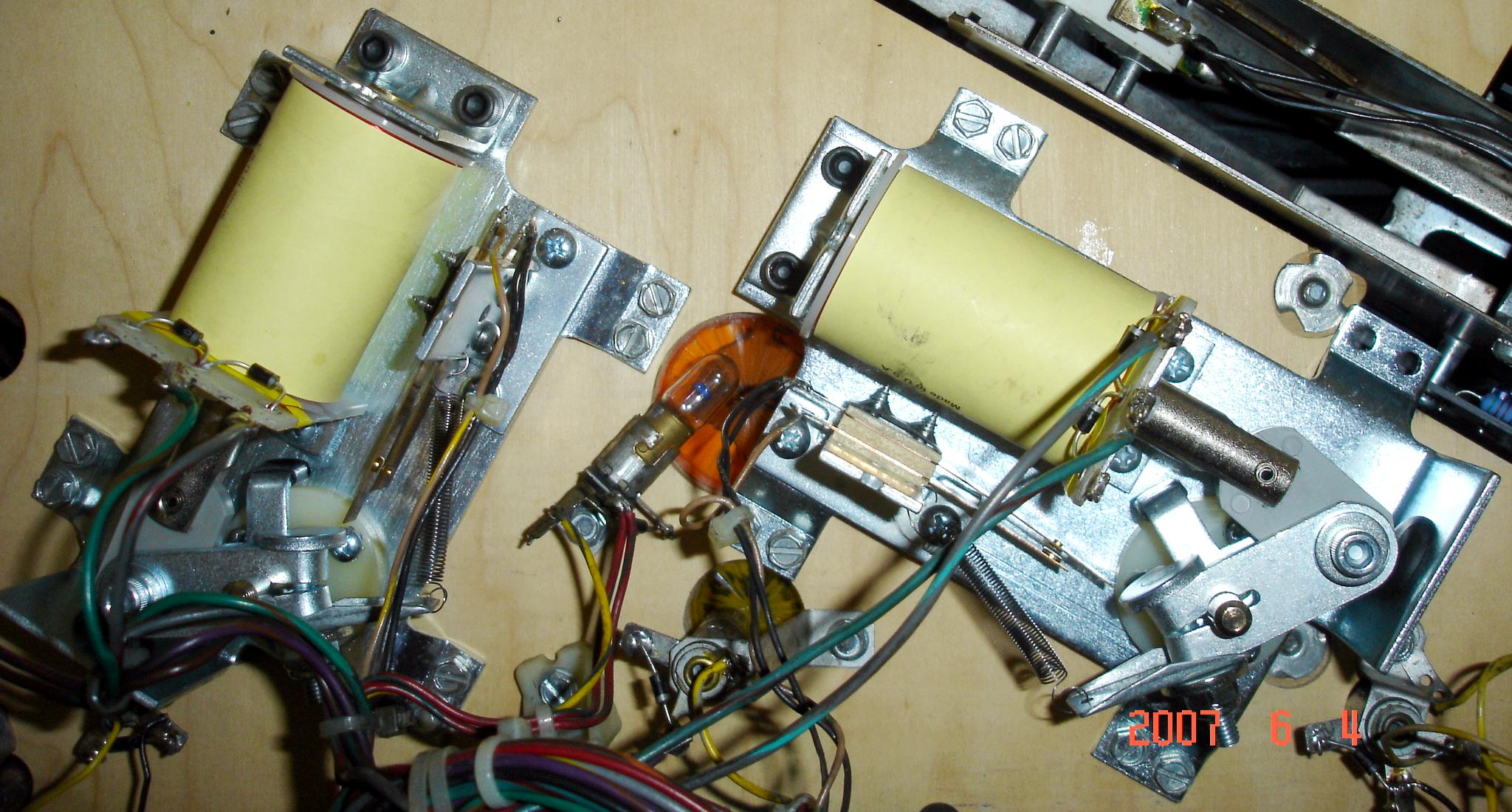
Williams Flippers on Capcom.
Due to the price of Capcom flipper parts,
some have converted to using (the much
cheaper and easier to get) Williams flipper
mechs. Rich Wiski sent me this picture
of Williams flipper mechs in his Pinball Magic.
Note the usage of Williams FL-11629 flipper coils,
with one lug going unused.