06/21/07, by cfh@provide.net
Ok I admit I'm not the best video game tech. But as a pinball hack, I find myself in a position where I need to occassionally fix video games. The single biggest thing that needs repairs in the "classic" coin operated video games (1980-1984) are monitors. Games like Pacman, Ms. Packman, Galaxians, Gorf, Galaga, etc. all used the Electrohome G07 monitor. Think of the ElectroHome G07 as a 30 year old TV set (though it's really not, but that would be a good analogy). And this one monitor was most popular during the "classic" video years of 1980 to 1984. Of all the video games I see, this and the Wells Gardner 4600 are the two that were used the most.
So anyway, I decided to put together a document on how to systematically repair the ElectroHome G07. Note this won't fix every problem, but it will fix most. The reason I use this approach is simple - I really didn't want to spend a boatload of time learning how to fix monitors, so a systematic approach was one that I could apply to the ElectroHome G07 and get it working 90% of the time.
Typical G07 Problems.
Most monitors I encounter are DOA. That is,
they are dead. (If they weren't dead, people
wouldn't be calling me.) The most common cause is that
the electrolytic capacitors in the G07 dry out, thus
reducing their capacitance. Think of an
electrolytic cap as electriconic jelly roll, and with
time and heat from the monitor, the jelly dries out,
making the caps deteroiate to basically doing just
short of nothing. This starts out with
a picture that is wavy or warping. But most people don't
fix this (with a "cap kit" as they are called, available
from many sources for about $10). What eventually happens
is the reduced capacitance stresses other parts, and the
monitor basically impodes.
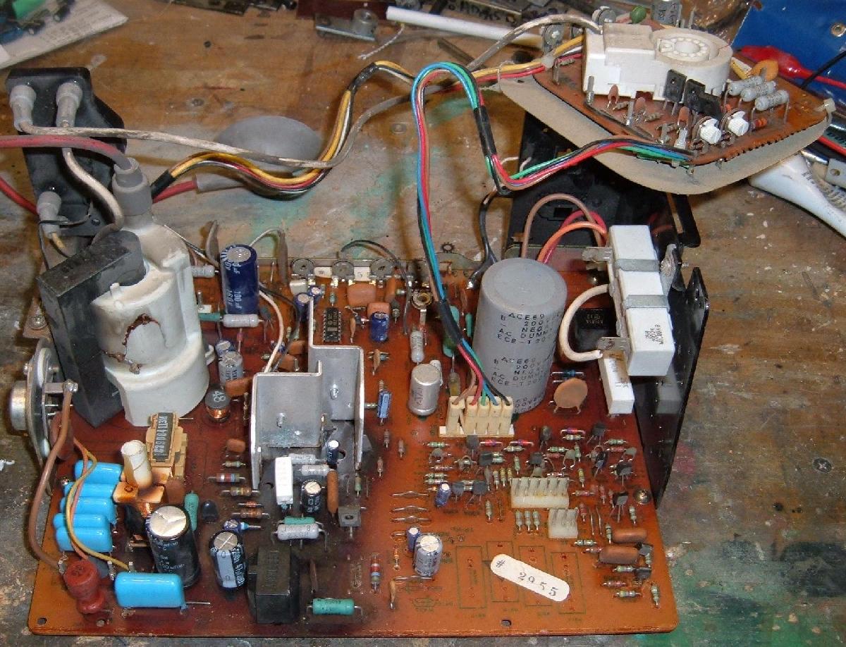
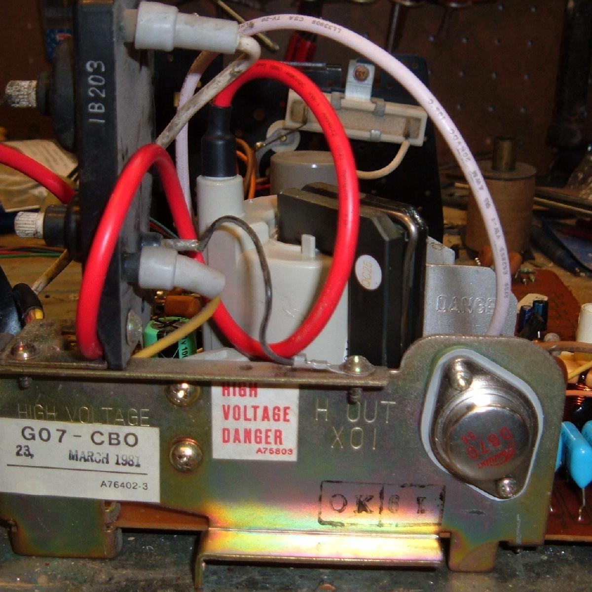
Below is a picture of one such G07, where the caps dried
out and the high voltage (HV) flyback transformer blew up. In
the process it also took out the Horizontal output transistor (aka H.O.T.).
Notice the HV flyback transformer has a huge crack along its side,
and goo has leaked out.
An imploded G07 monitor chassis and neck board removed and on the workbench.
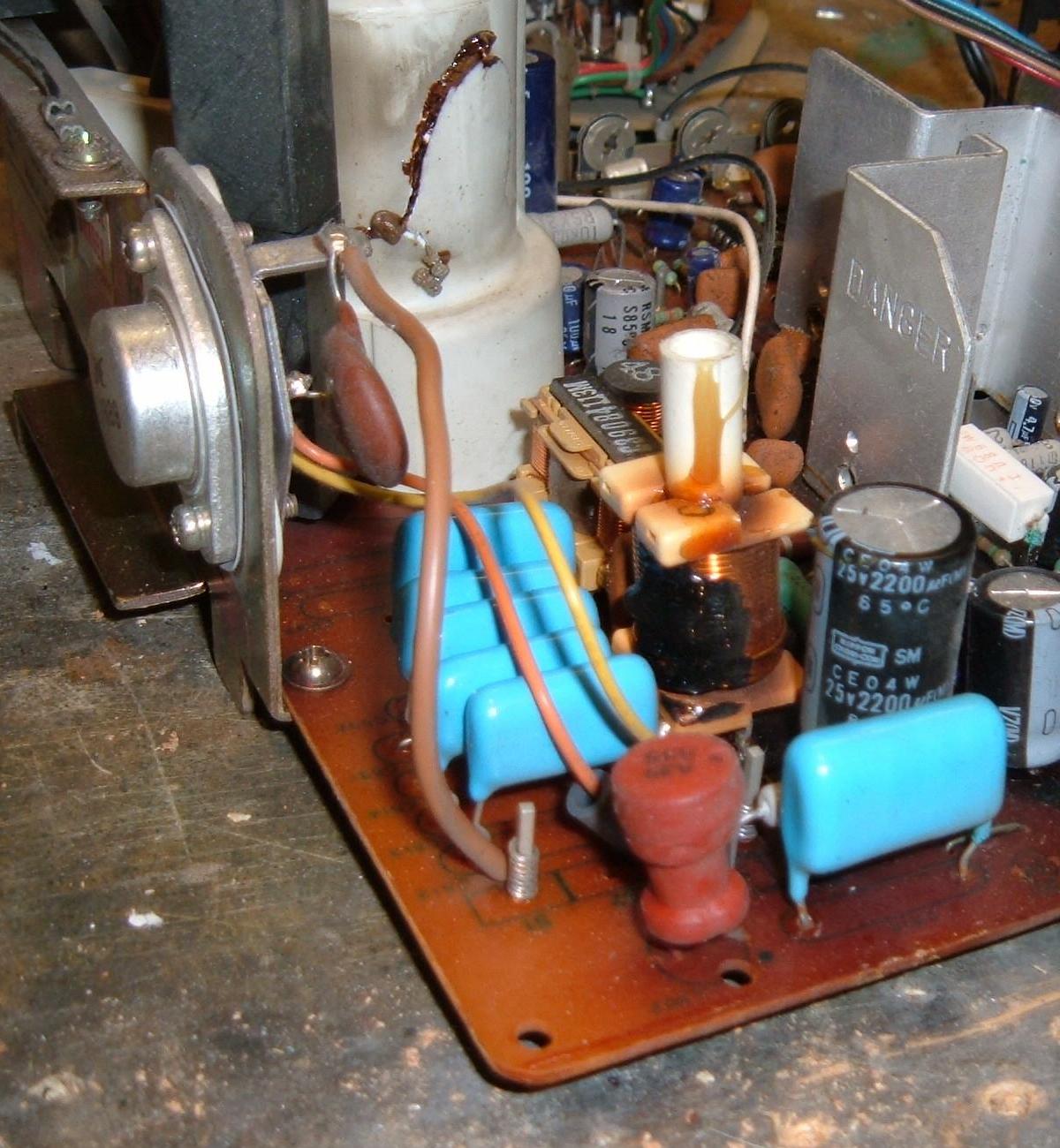
Close up of the cracked HV flyback transformer and the bad
Horizontal output transistor.
Note the cooked horizontal width
coil (even though it looks bad, it was actually fine).
G07 Monitor chassis Removal.
The first step in fixing the ElectroHome G07 is to remove
the chassis from the monitor frame/tube area. This is pretty
simple, at least at first glace. Two screws, about four connectors,
take off the neck board,
and removal of the big HV suction cup from the monitor tube.
But the tube and chassis MUST be discharged BEFORE REMOVAL.
-
HIGH VOLTAGE (HV) WARNING:
Remember those old worn out electrolytic caps I talked about? Well believe me, they ain't worn out as much as you might think. That is, they can still hold a charge. Caps are a somewhat mechanical device that store and discharge electrical current, many times per second. In the case of a monitor, this voltage is very high, like 20,000+ volts. Also, as goofy as it may sound, the picture tube itself acts like a large capacitor! That means it stores current too. All this comes together at the monitor Anode, which is connected at the monitor tube through the electrode beneath the suction cup on the side of the monitor tube. This anode needs to be grounded to discharge the caps and the picture tube. This needs to be grounded BEFORE DOING ANYTHING to the monitor (including trying to remove the monitor chassis).
Discharge the chassis & Monitor Tube.
Now there are many methods to discharging the electrolytic caps and
the picture tube. Frankly, if you don't know how to do this,
you SHOULD NOT BE DOING THIS REPAIR.
I'm not the one to teach you how to discharge
a monitor. Ok are we all clear on that? You can HURT YOURSELF BAD
with the shock coming from a monitor at the
HV flyback transformer anode. Trust me on this. I have done it.
I have literially be knocked on my butt off my feet from forgetting
to discharge a monitor, or by doing it wrong.
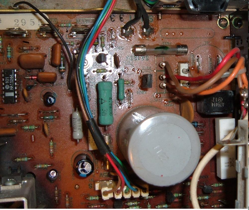
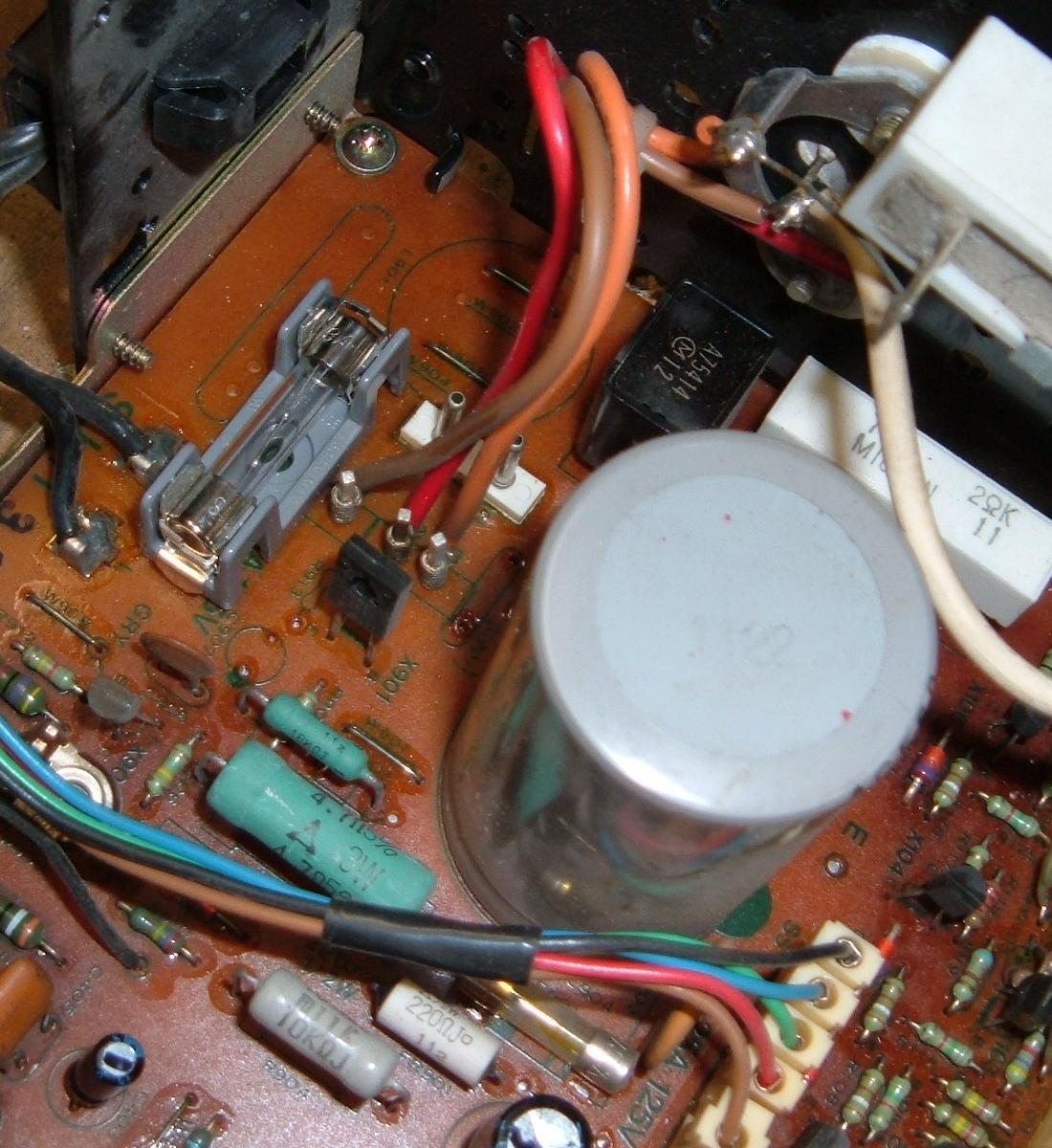
Blown or Missing Monitor Fuse.
Another caution should also be stated. That is,
most monitor chassis can be handled without shock after the
HV flyback transformer anode is grounded. But if the monitor
has a blown fuse F901 (right next to the BIG c904 cap)
or fuse F902 (behind the flyback closest to the back edge of the
monitor chassis), a charge could still be stored in the LARGE c904 cap
on the monitor chassis. So it's a good idea to use an alligator
clip across the F901 fuse (the fuse right next to the HUGE c904
cap, in case its blown), and then again
ground the HV flyback transformer anode. You can do this
before or after the chassis is removed from the monitor frame
(of course it's better to do it before).
If you don't do this, a stored charge in C904 could wreck
a DMM because of the stored current (not to mention it
could shock you).
If you have recently powered on the G07 chassis and the F901 fuse (closest to C904) was blown, then C904 has a nice fresh charge in it just waiting for you to provide a path to ground. Some caps hold their charge for years, while others dissipate in a matter of hours or weeks. So always discharge the G07 monitor chassis with F901 installed or with it jumpered with an aligator clip.
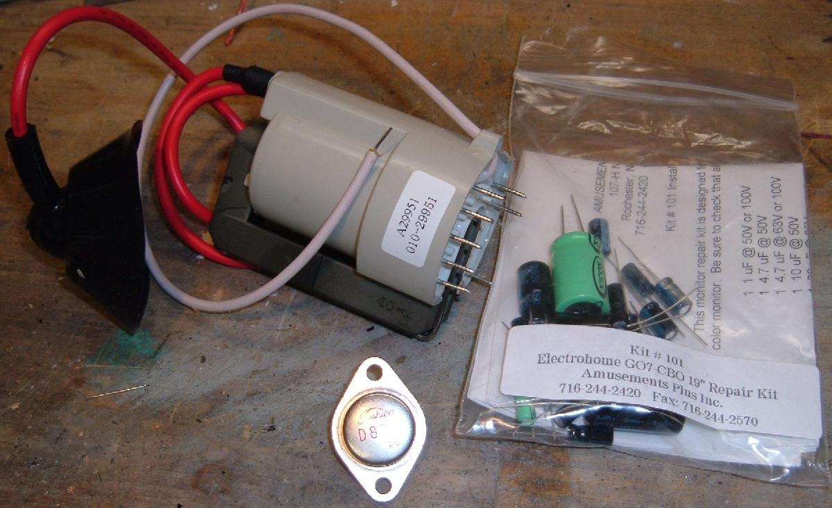
Stuff you'll need to buy for a typical Electrohome G07 monitor rebuild (flyback, 2SD870
output transistor, cap kit). You may need a new horizontal width coil, but I don't
replace that unless absolutely needed. Especially since they are hard to get.
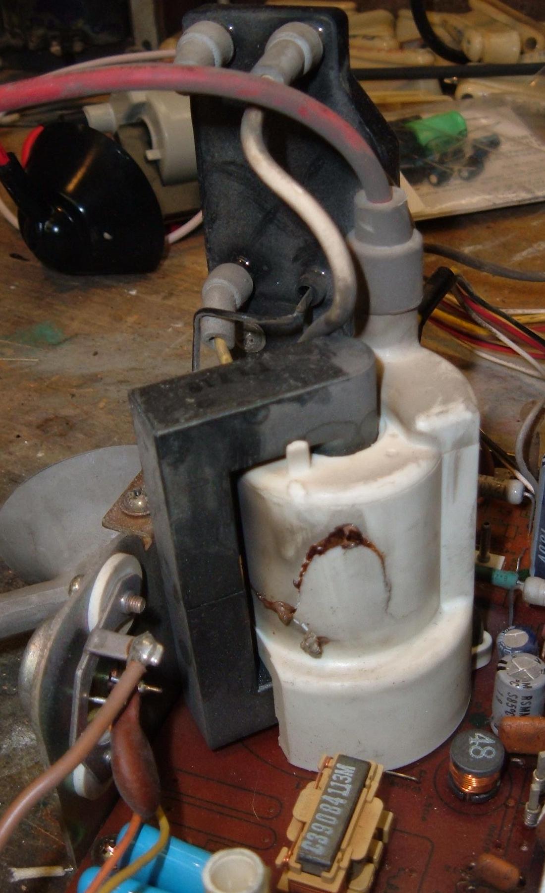
HV Flyback Transformer.
More and more dead G07's I am seeing have
their flyback transformer exploded. It's real easy
to identify this - just look at the picture above and you'll
know just what I mean. When the go, they go hard, with a big
crack down the side and some goo that oozes out. Obviously
this must be replaced.
Many people will, as a precaution, just replace the Flyback with a new one. They are not expensive, about $20. Frankly if you're going through all this work to rebuild a G07, you might as well install a new flyback. Because if the flyback implodes, it WILL take out several electronic parts with it. If usually takes out the F902 fuse, the Horizontal output and/or Regulator transistors, and perhaps an electrolytic cap or two in the process. Because of this, just replace the flyback and be done with it. Otherwise you'll be going through this whole G07 rebuild procedure again when the 30 year old flyback dies.
The dead flyback and horizontal output transistor.
Replacing the flyback is pretty easy. There are about eight solder points on the bottom of the monitor chassis that must be desoldered. And TWO screws on the side of the chassis that must be removed (which stablize the flyback). Don't forget to remove those two screws!
After the old flyback is out, don't put the new one in just yet. I do this dead last. Because it's a lot easier to do the all the other G07 chassis work with the flyback removed.
Testing the Output Transistors.
If the flyback imploded, chances are excellent either or both
of the large output transistors went with the flyback.
The horizontal output transistor (aka HOT) H-OUT X01 is closest
to the flyback, and almost for certain is shorted. This is
easy to test using a DMM set to the diode setting.
The horizontal output transistor X01, mounted by the
flyback. This is a 2SD870 transistor.
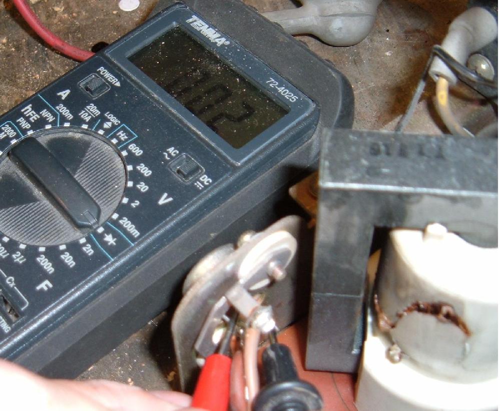
With a DMM set to the diode function, put the DMM leads on the two legs of the Horizontal output transistor (black DMM lead closest to the flyback). For the Regulator transistor C1106 on the other side of the chassis (furthest away from the flyback), put the black DMM lead on the transistor lead closest to the back of the monitor chassis. You should see a value between .150 and .600. A dead short will show as .010 or less.
Testing the horizontal output transistor mounted by the
flyback. This 2SD870
transistor here is shorted (.002 on the DMM).
Testing the Regulator C1106 transistor mounted on the
other side of the G07 chassis.
This transistor here is good (.546 on the DMM).

When replacing an output transistor, first unsolder the wires from the transistor's legs. Then remove the two screws that hold the transistor to the metal chassis. Make sure you don't rip the insulating gasket under the transistor. Yes it's needed, so just be careful and you can usually reuse the old one. These insulators can be polyimide (thin yellow plastic), mica (translucent white), or elastomer (gray flexible rubber). Sometimes a very thin layer of silicon insulator grease (heat sink compound, Radio Shack) is used, but personally I don't add any. The grease fills the tiny holes in the metal to help with heat transfer (that's why you use a very thin layer).
The new transistor will only mount one way (unless you force it!) Do a continuity check between the outside of the transistor's metal case and the metal frame it mounts to - there should be no continuity. If there is continuity, you must replace the rubber or mica transistor insulator. If you fail to do this, you will kill the new transistor (and of course the monitor will not work).
When resoldering the wires to the new transistor make sure you don't mix up the wires. Also solder the wires to the ends of the transistor legs so they don't short against the metal frame or metal retainer. And don't forget the round insulating ceramic discs that mounted on the inside between the monitor frame and the metal wire holder. These insulators keep the mounting screws from shorting the metal case of the transistor to the metal chassis frame. The screws actually need to connect the transistor case (the collector) to the isolated metal retainer (and NOT the metal monitor frame), where it is then fed to the primary winding of the flyback transformer.
Note do not touch either output transistor while the monitor is powered on as there is high voltage there!
Resolder the Male Connector Pins and Large Resistors.
Another common failure point for these monitors are the .156"
male connector header pins on the monitor chassis board. Since
the chassis board is a single sided circuit board (only traces
and solder points on the bottom of the board), there isn't a lot
of contact area for things to be soldered. This encourages
cracked and/or cold (dull gray) solder joints, which mean
intermittent connections.
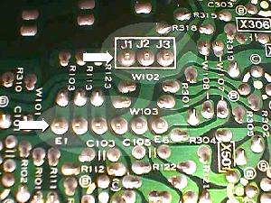
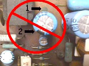
The two headers W102 and W103 are very important to resolder They are the negative sync (3 pins, top arrow in pic below) and the video & positive sync (6 pins, lower arrow in pic). If these pins are loose or the solder joints for the pins cracked, this is will cause a video sync problem, or missing color(s), or lack of vertical or horizontal sync, or any combination of these. If only one of the two grounds is connected, you will have nothing on the screen but a negative picture that cannot sync.
Some of the male header pins on the solder side
of the board. These are the video and sync headers.
Picture by Bob Roberts.
The video and sync male header pins and large resistors that need to be resoldered.
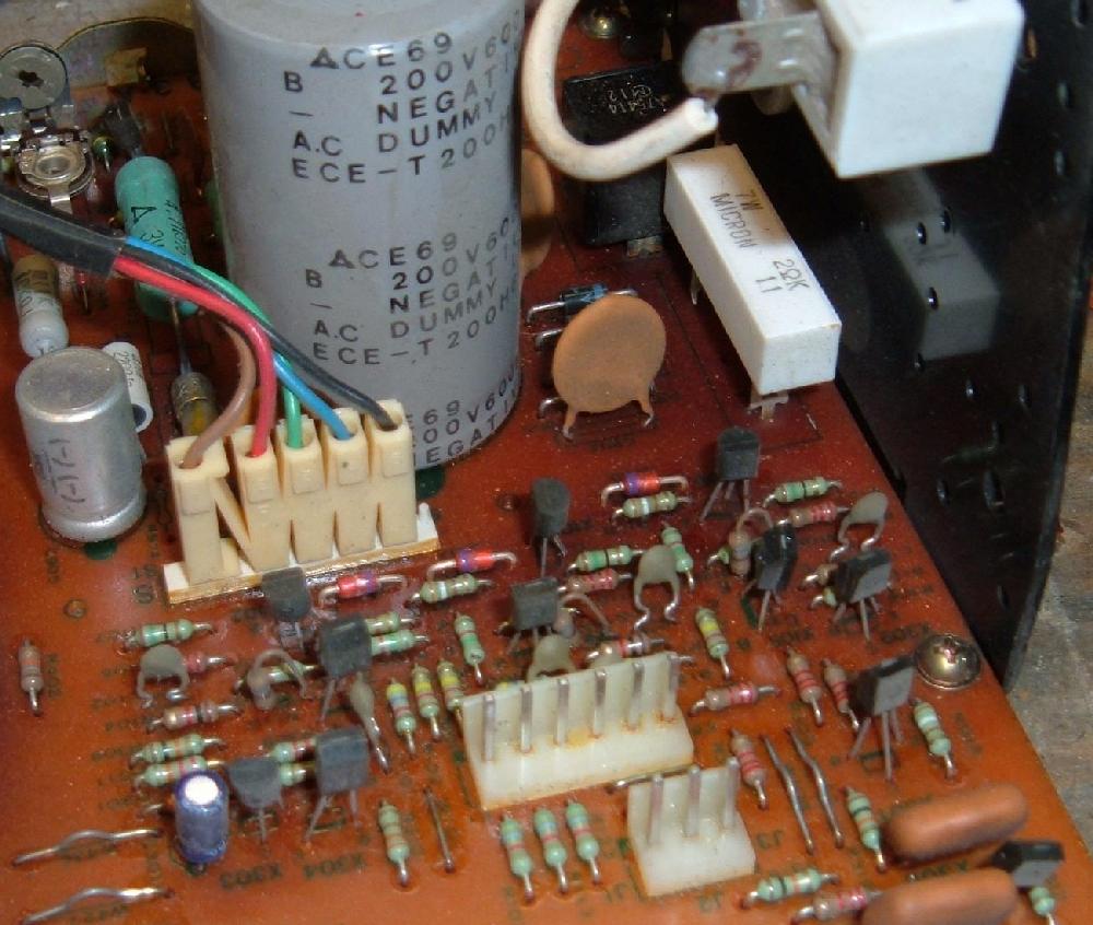
Also any large resistors (1 watt or larger) can get cracked and/or cold solder joints, and need to be resoldered. These are scattered along the monitor and neck board. A quick visual examination should locate any of these. And lastly check the neck board for cold or cracked solder joints.
The absolute best way to resolder these connections is to first remove the old solder. I use a cheap solder depullit device (Radio Shack) and desolder the contact points. Then I resolder them with new fresh solder.
Check the Fuses.
There are two fuses on the G07 monitor chassis.
The one that usually blows (especially when the flyback
implodes) is the fuse mounted at the back edge of the
chassis board, fuse F902. This is a solder-lead style
fuse. I don't suggest using that style. Instead replace
it with a PC board mount fuse holder. You can check the
fuse with a DMM set to continuity (monitor power off
obviously).
The F902 fuse at the back edge of the chassis board.
This fuse is most likely to be blown,
especially if the flyback died.
The F902 fuse at the back edge of the chassis board,
after replacement with a fuse holder.
Horizontal Width Coil.
The horizontal width coil is something that often looks
burned up and broken, but usually really isn't. All this
coil consists of is a ferite core and wire wrapped around
it, mounted in a plastic frame. The plastic often cracks
and looks damaged, but the coil is usually Ok. You can
replace this if you wish, but generally I do not. It's
nice to be able to adjust the horizontal width, but
since the enemy of good is better, I tend to leave this
part alone. Also replacement Hwidth coils are hard to
find, as they appear to be discontinued.
Warning: If you have the monitor chassis upside down to solder the bottom of the board, often the Horizontal Width coil acts like a "leg". This is obviously not a good thing, as the coil could be easily broken. Be careful, as even a burnt looking Hwidth coil is usually fine, and replacements are hard to come by.
Installing the Cap Kit.
Installing the cap kit is the least fun of any
of these tasks. The caps MUST be installed correctly,
or you will certainly blow up a reversed cap (and maybe
some other components to boot). So don't get this step
wrong.
A capacitor's longer leg is the positive lead. Negative on the cap is also indicated by a band on the body of the cap, usually with a "�" sign. On the G07 chassis board, negative is indicated on the parts side of the board as a solid dot on the circle indicating where the cap installs. There is often a dot on the solder side of the board too, again indicating the negative lead of the cap.
Note the C302 cap has the polarity INCORRECTLY screened on the SOLDER side of the board. Interestingly the C302 polarity on the parts side of the board is correctly marked (just to confuse you).
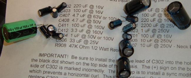
The G07 cap kit should include the following capacitors:
- C506 - 25v 33 mfd
- C403 - 25v 100 mfd
- C517 - 25v 100 mfd
- C701 - 25v 100 mfd
- C302 - 25v 220 mfd *Note* polarity is incorrectly marked on solder side
- C518 - 25v 220 mfd
- C521 - 25v 2200 mfd
- C504 - 50v 1.0 mfd
- C408 - 50v 4.7 mfd
- C303 - 50v 10 mfd *Optional* see note below
- C407 - 63v 4.7 mfd
- C412 - 160v 3.3 mfd
- C511 - 160v 47 mfd
- C411 - 160v 100 mfd
- C523 - 250v 1.0 mfd
- C107 - 250v 10 mfd (Neck board)
- C905 - 250v 10 mfd
- R908 - 47k 1/2 watt resistor
Occasionally cap kits may substitute a higher voltage cap than indicated above. Higher voltage rated caps are fine, but using a lower rated cap is a bad idea (though some kits will do this, because they know a lot more about this monitor than me).
Note that EVERY ELECTROLYTIC CAP EXCEPT THREE get replaced on the G07 monitor chassis board. The only caps that don't get replace are C301, C520 and C904 (the big cap).
When I get a cap kit, I organize the caps into the installation
sheet to help aid me
in their installation.
After you have installed all the caps, VISUALLY CHECK from the parts side of the board that you did not install any backwards! I can't stress this enough - installing a cap backwards will cause an explosion (yes the cap explodes), and this will kill all of your enthusiasm in doing this project.
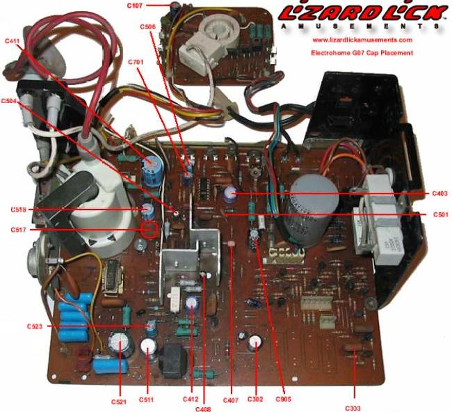
B.Roberts has a nice tip for checking cap orientation. If you look at a G07 Cap Map you'll notice that a majority of the negative cap lead "bullets" on the monitor board are facing the front of the chassis or toward the flyback. There are only four that deviate from this pattern, and three of those are under the metal protection shield (missing in all these pictures) and out of sight.
The caps with black "X" marks on them are what get replaced.

A chart of G07 cap positions from Lizard Lick Amusments.
A chart of G07 cap positions from B.Roberts. Note the perspective is
horizontally reversed compared to the above two pictures.
There is an optional C303 upgrade. Personally I never do this upgrade (and frankly find no need for it), but some claim it helps with screen "curling" problems. Here are the steps for that modification.
- Remove C501 and discard.
- Remove C303 and install it where C501 was installed.
- Remove the solder from the hole that is in the middle of the two holes where C303 originally resided, and fill the C303 hole farthest from the board's edge with solder.
- Insert new cap (10 mfd 50v) in the cleaned holes, with the positive lead closest to the edge of the board (to the collector of X305).
- After installation, you may need to adjust the Horizontal Hold. Hole you don't have to, as the HHold coil is usual pretty fragile from heat stress. Leave it alone if at all possible.
Check or Replace Resistor R908.
The resistor R908, a 47K ohm 1/2 watt resistor
(right next to the F902 fuse at the back of the chasis),
is often way out of spec. This especially happens
if the flyback transformer died. The added strain
of a failing flyback puts a lot of stress on this
resistor. So at minum check the resistor, or just
replace it. Many cap kits come with this resistor
just in case.
Install the Flyback.
Now that all the work is done on the chassis board,
it's time to install the flyback transformer. Don't
forget the two screws that hold the transformer in place.
The one wire coming off the flyback (not the suction cup)
needs to get attached to the focus/brightness knob tree.
I cut the old wire off with about a 1/2" to give, butt
solder the new one wire to the old stub, and then put
the new wire hood over the butt connection. A dab of
silicon will keep the wire hood in place.
Check the Neckboard RGB Transistors.
There are three transistors on the neck board that
control the Red-Green-Blue guns inside the monitor
tube. If one of these transistors is bad, the monitor
will be missing that color (and look really bad).
These three transistors are easy to check using a DMM
set to diode setting. Replace any questionable transistor.
Double Check all Capacitor Installations!
from the parts side of the monitor chassis, give a good
look at all the caps and the dots on the board. The dots
should line up with the negative band on the caps. A
backwards installed electrolytic cap WILL blow up, spewing
bits of goo and aluminum all over the place.
A MIS-INSTALLED cap on a G07 chassis.
The black line on the cap should be next
to the green dot on the circuit board.
Picture by Bob Roberts.
Clean Up Your Solder Work.
If you're not a soldering ace, I would highly
suggest taking some dollar store alcohol and
a small wire brush (available at Home Depot in
the welding department), and clean off all
excess flux and other solder junk. This will
make inspection of your work much easier.
And then you can look for...
Lifted Solder Pads.
Broken solder pads are another typical problem on G07
monitor boards. Since this is a single sided board,
the pads lift REALLY easy. This can isolate a freshly
installed capacitor from it's connecting trace. Not a
bad idea to use a DMM set to continuity to check
all cap pads to make sure they buzz out to their
nearest component.
Isolation Transformer: REQUIRED.
This applies to all monitors of this vintage.
An isolation transformer (primary 120 volts,
secondary 120 volts) IS REQUIRED. You can NOT
plug the power cord of a G07 monitor directly
into wall 120 volts, it must go through an isolation
transformer first. If you power
up one of these monitors without an isloation
transformer, you are asking for trouble!
If you're lucky, the only damage will be one of the diodes
at D901 to D904 is shorted (these are acting like a
bridge rectifier). If it got
past the bridge, look at the voltage regulator X04 next and beyond
(schematics needed).
All Done!
Now re-install the chassis and neckboards into the Electrohome
G07 monitor frame. Don't forget all the connectors (including
the ground wire going to the neckboard) and the
HV flyback electrode. When you power up the monitor for the
first time, do it while watching the back of the monitor and
the monitor chassis. This way you can see if anything "pops"
when power is applied, and quickly unplug the monitor!
The new flyback will require you to adjust the focus
and brightness knobs mounted to the flyback. The focus
is the top most knob (furthest away from the circuit board).
Note sometimes the picture can be "weak". This is another
problem with a 30 year old monitor. You need a tube rejuvienator,
which is a whole other subject, which won't be covered here.
(What happens is the color guns inside the monitor get covered
in crap, and won't give a good strong picture.)
Return to the Marvin3m.com fix-it web page.
Contact the Author.