LED Skull Pile Eyes Upgrade

    Introduction.
    This procedure will add LED eyes to your Deadhead "skulls" on a Scared Stiff pinball. Originally this was incorporated into the sample games, but was removed from the production games to save money. This modification will add the LED eyes back to your production game. There is one operational difference between this modification and the sample game LED's; the eyes will trigger off the games six different "tales", opposed to the rollover targets (which is how the sample games were originally set up).

    The six tales as shown on the playfield of Scared Stiff.
    The playfield lights used here will also light the skull's
    LED eyes.

    1b. LED Skull Eyes: Necessary Parts and Tools

      You will need the following parts for this modification:
      • (12) Water clear red 5mm LED's. Colored LEDs can also be used. In this case, two each of Amber, White (clear, white light), Blue, Yellow, Green and Red. Formerly Hosfelt part# 25-349, $0.35 each (current part number unknown).
      • (6) 1/4 watt 100 ohm resistors. Hosfelt part #1/4W-100, $0.03 each.
      • (6) 1N4004 diodes. Radio Shack or Hosfelt part# 1N4004, $0.07 each.
      • (2) Molex 9 pin .062" connector plug, with detent only. Hosfelt part# 03-06-2092, $0.56 each.
      • (5) Molex male .062" crimp-on pins. Hosfelt part# 02-06-2103, $0.09 each.
      • (3) feet of 1/8" Heat shrink tubing.
      • (9) feet of red wire.
      • (9) feet of yellow wire.

      Tools you will need for this modification:

      • Soldering iron and solder.
      • Connector cripping tool, Radio Shack or Hosfelt part# W-HT-1921, $12.95.
      • Phillips head screwdriver.
      • Masking Tape.
      • Thick style Super Glue or a Hot Glue Gun.
      • Molex pin extraction tool (optional), Radio Shack or Hosfelt part# W-HT-2285, $12.95.

      Hosfelt's phone number is 1-800-524-6464.

    1c. LED Skull Eyes: Assembly Procedure

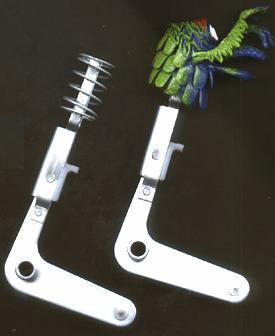
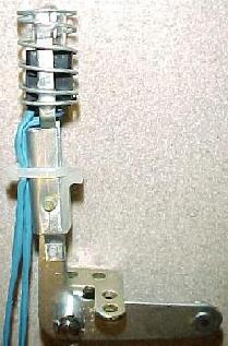
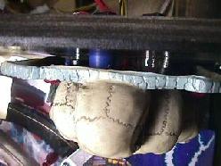
    Step One: Remove the Skulls.
    After removing the playfield glass, lift the playfield about eight inches and pull it back. Using a phillip head screwdriver, remove the two screws holding the skulls to the black back wood support. Be careful not to lose the two small black plastic spacer that the screws go through.

Left: the two screws holding the skulls in place.
Right: view from the top, showing the two small plastic spacers.


    Step Two: Assembly the LED Assemblies.
    There are two sides to each LED (light emitting diode); the cathode and the anode. These are identified by the "flat side" on the LED's. You'll have to look closely to see it, but you will need to identify the "flat edge".

This picture shows the "flat edge" of the LED's.

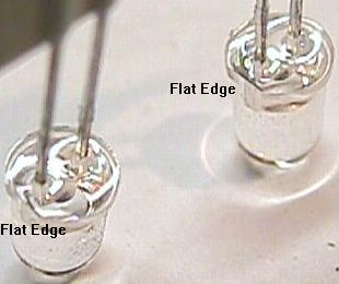
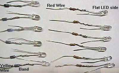
    To assemble one "eye" worth of parts, do the following:
    • Solder the BANDED side of a 1N4004 diode to the ROUND side of one LED.
    • Solder a 100 ohm resistor to the FLAT side of another LED.
    • Connect the unsoldered leads of the LED together. Twist the two unsoldered LED ends together.

    At this point, *TEST* your LED/diode/resistor installation to make sure it works. I suggest lifting the playfield, and test connecting the modified LED eyes to one of the "tales" light sockets under the playfield. If the eye LEDs do not work, the attached 1N4004 diode and resistor are "reversed". To fix this, connect the banded side of the 1N4004 diode to the FLAT side its LED, and solder the 100 ohm resistor the ROUND side of the other LED. Then retest. I bought my diodes from Hosfelt, and it turned out they were mis-manufacturered and the flat side was mis-labeled! So always best to assemble one and make sure it works before doing all the others.

    To be honest, the 1N4004 diodes are probably not really necessary. The LEDs themselves are essentially diodes anyway. So adding a 1N4004 diode is redundant. But I added them anyway. The resistors though are necessary!

    After the installation of the resistor and diode is confirmed and verified, solder a 1.5 foot length of YELLOW wire to the other NON-BANDED side of the 1N4004 diode. And solder a 1.5 foot length of RED wire to the other side of the 100 ohm resistor. Also solder these two twisted LED leads together.

    Finally put a length of 1/8" diameter heat shrink tubing over the diode and lead of the LED, and heat shrink the end so it doesn't move. Also put a length of 1/8" diameter heat shrink tubing over the resistor and lead of the LED, and heat shrink the end so it doesn't move.

    Now repeat for the other five sets of eyes.

Shown are the diodes and resistors soldered to each LED.
Note the (flat or round) side of the LED matters! If you
do this step incorrectly, the LED's will never work! Also
note the banded side of the 1N4004 diode goes toward the LED.

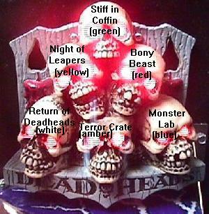
    Step Three: Insert the Paired Eyes into the skull.
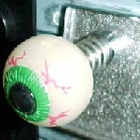
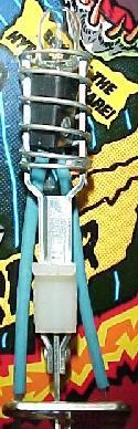
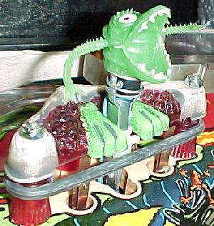
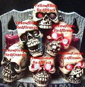
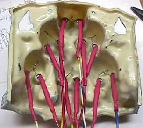
    Insert each pair of LED eyes into the skull; they should slip in fairly easily. You can secure the LED's with a hot melt glue gun or some thick-style super glue if desired. After installing, use some masking tape and label each of the two wires coming off the eye pairs. Label them top, middle left, middle right, bottom left, bottom middle, bottom right as appropriate. Which LED goes to which wire DOES matter (kind of). The order shown below in the picture used here works well, and makes the attract mode look better.

    If using different colored LEDs, here is a good suggestion for order.

    • Amber=Terror from the Crate
    • White (clear, white light)=Dead Heads
    • Blue=The Monster's Lab
    • Yellow=Night of the Leapers
    • Green=Stiff in the Coffin
    • Red=Bony Beast

Left: The skulls and which wires in the lamp matrix they connect.
Right: The eye pairs as installed into the skulls. Note the two non-component LED leads are soldered together. The red heat shrink tubing hides the diode or resistor that is soldered to the legs of each LED.

      Step Four: Add the Yellow Wire Connector Plug.
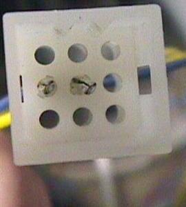
      Take the three bottom row yellow skull LED wires and tie them together. Put a single crimp-on male .062" molex pin on these wires. Plug this pin into the very center hole of the molex connector plug. This connects to the column lamp matrix's yellow/green wire.

      Take the top, middle left, and middle right yellow LED skull wires and tie them together. Put a single crimp-on male .062" molex pin on these wires. Plug this pin into the connector plug's middle row, left hole (as facing the connector pins, as though you are the other connector). This connects to the column lamp matrix's yellow/blue wire.

    The yellow wires' Molex plug connector. The
    bottom three skull LED's go to the center plug.
    Note the "w" edge across the top of the plug
    connector.

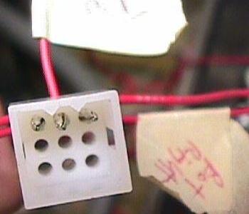
      Step Five: Add the Red Wire Connector Plug.
      Take the left bottom row and left middle row red LED skull wires and tie them together. Put a single crimp-on male .062" molex pin on these wires. Plug this pin into the connector plug's top row, left hole (as facing the connector pins, as though you are the other connector). This connects to the row lamp matrix's red/orange wire.

      Take the top and bottom middle row red LED skull wires and tie them together. Put a single crimp-on male .062" molex pin on these wires. Plug this pin into the connector plug's top row, left hole (as facing the connector pins, as though you are the other connector). This connects to the row lamp matrix's red/black wire.

      Take the right bottom row and right middle row red LED skull wires and tie them together. Put a single crimp-on male .062" molex pin on these wires. Plug this pin into the connector plug's top row, right hole (as facing the connector pins, as though you are the other connector). This connects to the row lamp matrix's red/brown wire.

    The red wires' Molex plug connector. The left bottom row and
    left middle row skull LED's go to the left connector pin. The
    top row and bottom middle row skull LED's go to the center
    connector pin. Note the "w" edge across the top of the plug
    connector.

      Step Six: Install the Skull back into the Playfield.
      With the skull LED eyes and connectors in place, install the skulls back into the playfield. The new skull LED wires go down to the playfield and through the large existing hole there. Don't forget the small black plastic spacers that go on the two screws that hold the skulls in place.

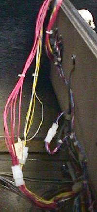
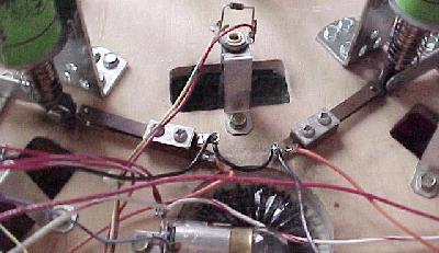
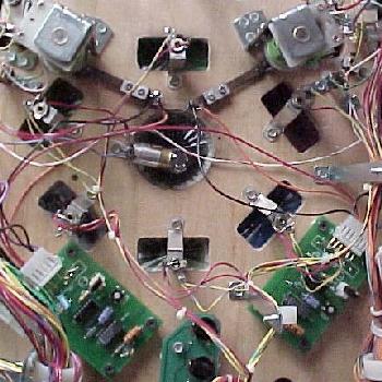
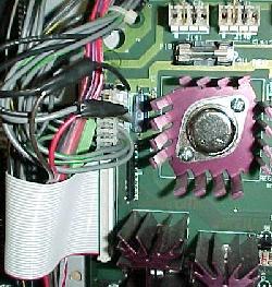
      Step Seven: Connect the New Plugs to the Wiring Harness.
      The two new connector plugs should plug right into the wiring harness at the back of the playfield. There will already be two lamp matrix plugs there. Note one connects to a set of red wires, and one connects to a set of yellow wires. Connect the new yellow wire plug into the wiring harness' yellow wire connector. Likewise, connect the new red wire plug into the wiring harness' red wire connector. Also beneath the playfield there is a white plastic wire guide that the existing wiring harness passes through. Put your skull wires in the wire guide too to relieve strain on the LED's.

    Left: The new connector plugs attached
    to the existing wiring harness at
    the back of the playfield.
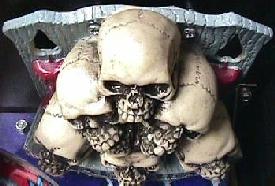
    Right: The new skull LED's installed
    and turned on.


    Eyeball Shooter Upgrade

    Introduction.
    On the original Scared Stiff prototype game, the manual ball shooter had an eyeball on the tip of the shooter. For some reason, this part was replaced with a normal Williams shooter with the round gray ball end.

    A new "eyeball" shooter.

    2b. Eyeball Shooter: Necessary Parts and Tools

      You will need the following parts for this modification:
      • Rubber Eyeball. These are actually 1.25" superballs. Available at http://www.jrousek.com/balls0.htm, part# 893, 50 for $12.95 (sorry, can't buy just one!) or pre-made and assembled from http://www.geocities.com/Area51/Shire/2747/kiteye.html.
      • Shooter Shaft. This is the standard Williams part used on all their pinball games with manual shooters, part# 20-9927-1. You can also use your existing shooter.
      • 3/8" Drill bit and drill.
      • Epoxy glue (24 hour dry type).
      • Hammer.

    2c. Eyeball Shooter: Assembly Procedure

      Follow these steps to make your eyeball shooter:
      • Using a hammer, break the plastic end of your new (or existing) shooter shaft.
      • Drill a 3/8" hole in the back side of the rubber eyeball, opposite of the eye's iris. Drill the hole 3/4" deep.
      • Mix up some epoxy and put it in the drilled hole in the eyeball.
      • Insert the shooter shaft into the drilled eyeball hole. Wipe off any excess expoxy with a rag.
      • Let the epoxy dry 24 hours.
      • Install the new eyeball shooter shaft into your pinball game.


    Frogs Replacement Parts

    3a. Frogs: Necessary Parts and Tools

      The frogs ("leepers") on the Scared Stiff pinball can become damaged. Fortunately, they are replacable.

      To install a new frog, you will have to drill the bottom of the frog with a 1/8" drill bit and insert the activator into the hole.


    Boogie Men Modification

    Introduction.
    The original boogie men in Scared Stiff were attached to the slingshot kicker arms in the preliminary sample games. During boogie man mode, the software energizes the slingshot kickers on beat with the boogie man music. It makes the men "dance" to the beat. A very nice touch!

    Sample game style slingshot kickers, used to
    make the boogie men "dance".

    During testing of the sample games, Williams noted the boogie men self-amputated their arms from the slingshot kickers. To "fix" this problem, they made the boogie men stationary in the production games. But even the latest version of the game software still makes the slingshot kickers "kick" during boogie man mode.

    You can make the slingshot extensions though. For example a guy named "dirtrider" made them using 1/2" copper pipe, flattened in a vice, and then cut out with a Dremel cutoff wheel. Check out his pictures below, it looks like a nice idea.

    You can't buy the parts to make the boogie men dance. Since these parts are essentially unavailable, I came up with another idea to make the boogie men "dance".

    Another idea is to add flasher bulbs to the slingshots. Now during boogie man mode, the slingshots will still kick (assuming you have this option turned ON in the software), AND a flashlamp will light too. This gives the boogie men more "flash".

    Since I have no way to re-write the software to activate the new flashers, I used hardware instead. A switch is added to each of the two slingshot kickers. When the kicker is energized, it closes this new switch. Each switch is tied to its own Gottlieb "pop bumper driver board" (PBDB), which activates a flash bulb.

    Note that someone has made the original sample game style slingshot kicker parts, to make your boogie men really "dance". See http://www.geocities.com/Area51/Shire/2747/kitbm.html for more information on these.

    4b. Boogie Men Mod: Necessary Parts and Tools
    You will need the following parts for this modification:

    • (2) Pop bumper driver boards (PBDB). These are available from Pinball Resource for about $25 each. You can also use Gottlieb System 80 pop bumper driver boards too, which are availble used for less if you can find them. Both these boards have the same connection configuration, and either will work fine, and are plug compatible (if using Gottlieb PBDB's, make sure you modify them as outlined at http://www.marvin3m.com/sys80/index.htm#popbump).
    • (2) Molex 6 pin female .156" connector housings, part# 09-50-3061 ($0.39 each, avaiable from Hosfelt, 800-524-6464).
    • (2) Molex crimp-on .156" connector pins, part# 08-50-0106 ($0.06 each, available from Hosfelt, 800-524-6464).
    • (2) Lamp Sockets, Williams part# 24-8776. These are pop bumper lamp sockets used in newer Williams WPC pinball games.
    • (2) 12 volt flasher lamp bulbs #194 (small 555 style).
    • (12) inches of 3/32" shrink wrap tubing.
    • (2) Leaf style switches. I got mine from a used parts playfield, but Pinball Resource probably sells these too.
    • Mounting screws for the lamp sockets, leaf switches, and driver boards.
    • About 20 feet of 24 gauge wire.
The "Finger Frights" available from Funforalltoys.com.
These are exact boogiemen replacements.

    • (2) transparent Boogie men, available at http://www.funforalltoys.com (877-332-7697), part number "FFA 239" (Finger Frights), two for $1.00. These are exactly the correct boogie men, and are transparent enough so they work well with an internal lamp.

      You can also get similar boogiemen from http://www.jrousek.com/fpuppets.htm, part# 340, 72 for $7.95 (sorry, can't buy just two!). And they are also available from http://www.smilemakers.com, part# FP, 72 for $9.95. These are the style of boogie men as used on the 1989 Bally pinball "Elvira and the Party Monsters". This transparent style of boogie men work well because you can mount a #194 flasher bulb right inside the transparent boogie man's head.

      Non-transparent, Scared Stiff boogie men (not exactly like the sample games, but good replacements) are available from Smilemakers, part# MFP, 72 for $9.95. If you have sample game style moving boogie men, you should have spares as the boogie men do tend to get damaged easily (their arms amputate). Note these boogie men don't work with the following lamp modification because they are not transparent.

Left: Boogie men as used in "Elvira and the Party Monsters", 1989, from Smilemakers.com. These allow light to shine thru their body, and work great with a flash bulb mounted inside their body.
Right: Similar boogie men as used on the sample game of "Scared Stiff", from Smilermakers.com. These are not exactly the same as the sample games, but are decent replacements. Unfortunately, these are opaque and do not allow any light to shine through their body.

    4c. Boogie Men Mod: Installation Steps
    1. Remove the balls from the game, and lean the playfield against the backbox.
    2. Screw the pop bumper driver boards to the bottom of the playfield. I located them just below the "tales of terror" playfield inserts (see picture below). Be careful not to use screws that are too long as they could break through the top of the playfield!

    Installation of a PBDB's under the playfield under the "tales of terrior" light inserts.

    1. Screw the leaf switches under the playfield near the slingshot kickers. The plunger on the slingshot should OPEN the switch while it's in the resting position (see picture below).

    The leaf switch should be normally open while the slignshot kicker is
    at rest. When the slingshot is activated, the switch will close.

    Both slingshot kickers with their switches installed.

    All the parts installed under the playfield. Shown are the two
    PBDB's and their corresonding leaf switches (which are activated
    by each slingshot kicker). Also shown is the existing #89 flasher
    in the center of the "tales of terror" lamp inserts. This is where
    +20 volts is connected to each of the two new lamp sockets.

    1. Remove the slignshot plastic covers from the top of the playfield.

    Left: The new transparent boogie man mounted on it's original metal bracket. The lamp socket and #194 lamp are inside the boogie man's head. The socket is secured to the bracket with electrical tape. The socket leads are encased in 3/32" shrink wrap tubing.
    Right: The socket and #194 lamp installed in the sample game style kicking boogie man bracket. Again, the socket leads are encased in 3/32" shrink wrap tubing.


    If using the stock boogie men production setup, do this:

    • Remove the metal bracket holding the boogie men from the playfield.
    • Unbolt the old boogie man from the metal bracket.
    • Using a razor blade, cut a hole in the new transparent boogie men in the back of their head. Then install the new boogie men on their metal brackets, with the bolt through the back of their head. Add a washer so the new boogie men don't tear, and tighten the lock nut.
    • Install the #194 bulbs in the new lamp sockets.
    • Straighten the new lamp socket leads, and put 3/32" shrink wrap tubing over the metal leads. Cover the entire length of the leads (about three inches).
    • Put the #194 lamp and socket up and into the head of the new boogie men. Use some black electrical tape to secure the socket to the metal bracket.
    • Re-attach the boogie men and their metal bracket to the playfield. The socket leads should protrude through the playfield.

    Left: The pop bumper lamp socket and #194 lamp installed on the sample game style slingshot kicker. Note the position of the nylon tie, and the "knot" on the nylon tie.
    Right: The sample game style kicker and lamp socket installed.

    If using the Sample game style kicking boogie men, do this:

    • Straighten the new lamp socket leads, and put 3/32" shrink wrap tubing over the metal leads. Cover the entire length of the leads (about three inches).
    • Remove the current boogie man and put the new socket and #194 bulb inside the spring on the kicking assembly.
    • Using a nylon tie, secure the new heat shrunk socket leads to the slingshot kicking arm. The "knot" of the nylon tie MUST be on the BACKSIDE of the kicker assembly (see picture). The nylon tie should be located above the nylon piece that contacts the slingshot rubber.
    • Install the sample game style slingshot kicker in the game.
    • Slide the boogie man back onto the spring.

    A stationary, production game boogie man with a #194 lamp and
    socket inside his head.

    1. In the backbox, splice two 10 foot wires into the current wires at connector J101 on the power driver board. Any of the black wires on this connector are Ground. Any of the grey wires on this connector are +5 volts. You will need to run these wires through the backbox and down underneath the playfield, and up to the pop bumper driver boards.

    Connector J101 on the power driver board.
    The black wires are ground, the grey wires
    are +5 volts. Splice into these to get power
    and ground for the under-the-playfield pop
    bumper driver boards. You can see the spliced
    in red and brown wires.

    1. Run a wire from the factory installed #89 flasher bulb (in the center of the "tales of terror" insert) +20 volt lug, to one lead of the two newly installed lamp sockets. The power lug on the factory installed lamp socket is the lug with the two red wires. This provides power to your two new flash lamps.

    The following steps connects all installed parts to the PBDB. The pin numbers for the connector on the PBDB are this: 6 5 4 KEY 2 1.

    1. Connect the +5 volt wire (from connector J101 in the backbox) to pin 5 of each PBDB.
    2. Connect the Ground wire (from connector J101 in the backbox) to pins 2 and 6 of each PBDB, and to one lug of each of the installed leaf switches. I did this by running the ground wire to the PBDB pin 6, then jump the wire to pin 2, then jump the wire to one switch, then jump the wire to the other switch, and then jump the wire to pin 6 of the second PBDB, and finally jump the wire to 2 of the second PBDB.
    3. Run a wire from the other lug of each switch to pin 4 of its corresponding PBDB.
    4. Run a wire from the unused lead of each newly installed lamp socket to pin 1 of its corresponding PBDB. This provides ground to your new lamp sockets when the slingshot kicker is energized.

    With this modification, anytime the slignshot kicker is activated (either by a pinball, or by the software in boogie man mode), the newly installed flasher will light (even when the game is in attract mode). Note the coin door MUST be CLOSED for all flashers to work!


    * Go to the Pin Fix-It Index at http://marvin3m.com/fix.htm
    * Go to Marvin's Marvelous Mechanical Museum at http://marvin3m.com