by cfh@provide.net, 06/16/01.
Copyright 2001 all rights reserved.
Scope.
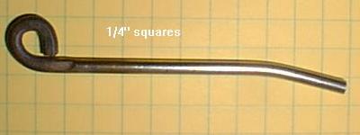
The 1993 Bally Twilight Zone slot machine playfield switch gets bent
from collision with the pinball.
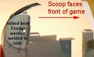
This allows the metal slot machine
ball scoop to be hit by the ball, splitting and breaking. If the
scoop breaks, this can only be fixed by welding.
Also, as the switch bends back, this can cause "air balls" when the pinball
hits the switch (the bent switch acts like a ski jump).
This causes broken playfield plastics (which are no longer
available from Williams). Reinforcing
the slot machine switch so it does not bend, prevents these problems.
|
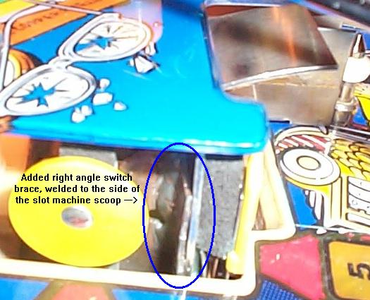
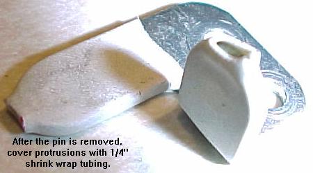
The problem slot machine switch and slot machine scoop on the Twilight Zone playfield. In this picture the slot machine switch has bent back, allowing the ball to hit the side of the slot machine scoop. This in turn has broken the weld, releasing the top metal part of the scoop. To fix this, the scoop will need to be re-welded. The bent switch will also need to be fixed, or the problem will happen again. The plastic above the switch has also broken, because the bent switch acts like a ski jump, launching the ball into the air and breaking the above plastic. |

|
-
Table of Contents
Some of these ideas were originally conceived by Jonathan Deitch. He has a nice Twilight Zone "fix it" web page at http://personal.atl.bellsouth.net/atl/j/d/jdeitch/tz-fixit.html. I have been collecting many other people's ideas on this modification too. So most of this stuff is not "my idea". This is an accumulation of lots of TZ Slot Machine switch modifications I have seen.