10/15/07, by cfh@provide.net
-
Overview.
- 4 Player Bowling Alley
- Amazing Maze
- Blue Shark
- Boot Hill
- Checkmate
- Clowns
- Datsun 280 Zzzap / 280 Zzzap / Midnight Racer
- Desert Gun
- Dog Patch
- Double Play
- Extra Inning
- Guided Missile
- Gun Fight
- Laguna Racer
- M-4
- Phantom II
- Road Runner
- Sea Wolf
- Shuffleboard
- Space Encounters
- Space Invaders
- Space Invaders Deluxe
- Space Invaders II Cocktail
- Space Walk
- Top Gun
- Tornado Baseball
The three games Sea Wolf, Space Invaders, Gun Fight all share the same Midway 8080 boardset. There are some minor differences in the boards for different games, but for the most part they are the same "L" shaped boards. It's a simple black and white system, and often the games have color cardboard or molded backgrounds to give color to an otherwise black and white system. Here's the list of Midway games that are alledged to use this board system:
Typical problems with these boards relate to the ROMs used. Midway had about 10 different styles of ROMs they could use. But today the best approach is to use 2716 EPROMs instead of the original ROMs. In order to do this, some jumper modifications will need to be made to the boardset. They are pretty minor modifications. Also all the ROMs need to be combined into 2716 EPROMs.
Other typical problems with this boardset relate to the 40 pin socket used for the Intel 8080 CPU chip (this socket almost always will need to be replaced).
Also the RAM chips often die on these boards. These can be tested though with a program that plugs into the board with a 2716 EPROM (which is another reason why the boardset needs to be converted to 2716 EPROMs.)
The last issue with these boards is the power supply. It gives +5, +12, -5 volts DC to the main boardset and sound board. But the power supply does more than that. There is a delay reset circuit on the power supply. If this reset circuit is bad, the boardset (even if good) will not boot. This is why it's difficult to change the original power supply with a switcher. The reset circuit provides a delay, so the 5 volt supply can statablize. On newer games (1980 and later), this delay is built into the CPU board, and is not part of the power supply. But on these older Midway games, the reset delay is part of the power supply. So even if the +5, +12, -5 volts is good, if the reset circuit is bad, the game won't boot.
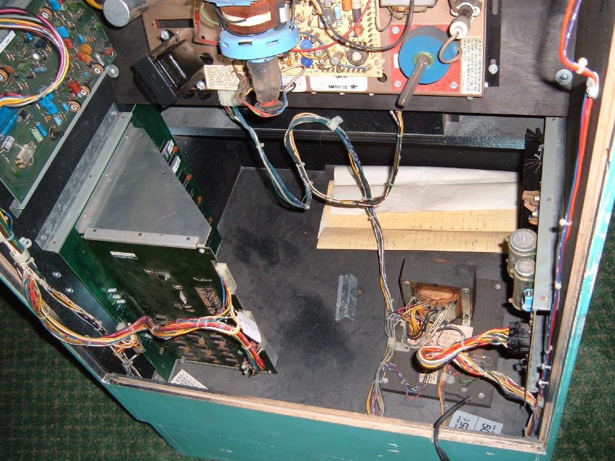
the Power Supply is not working.

here's the power supply (right side), transformer (bottom board), the "L" CPU boards
(lower left side), and sound board (upper left side) mounted in the back of a Midway
Sea Wolf upright game. Top center is the black & white motor chasis.
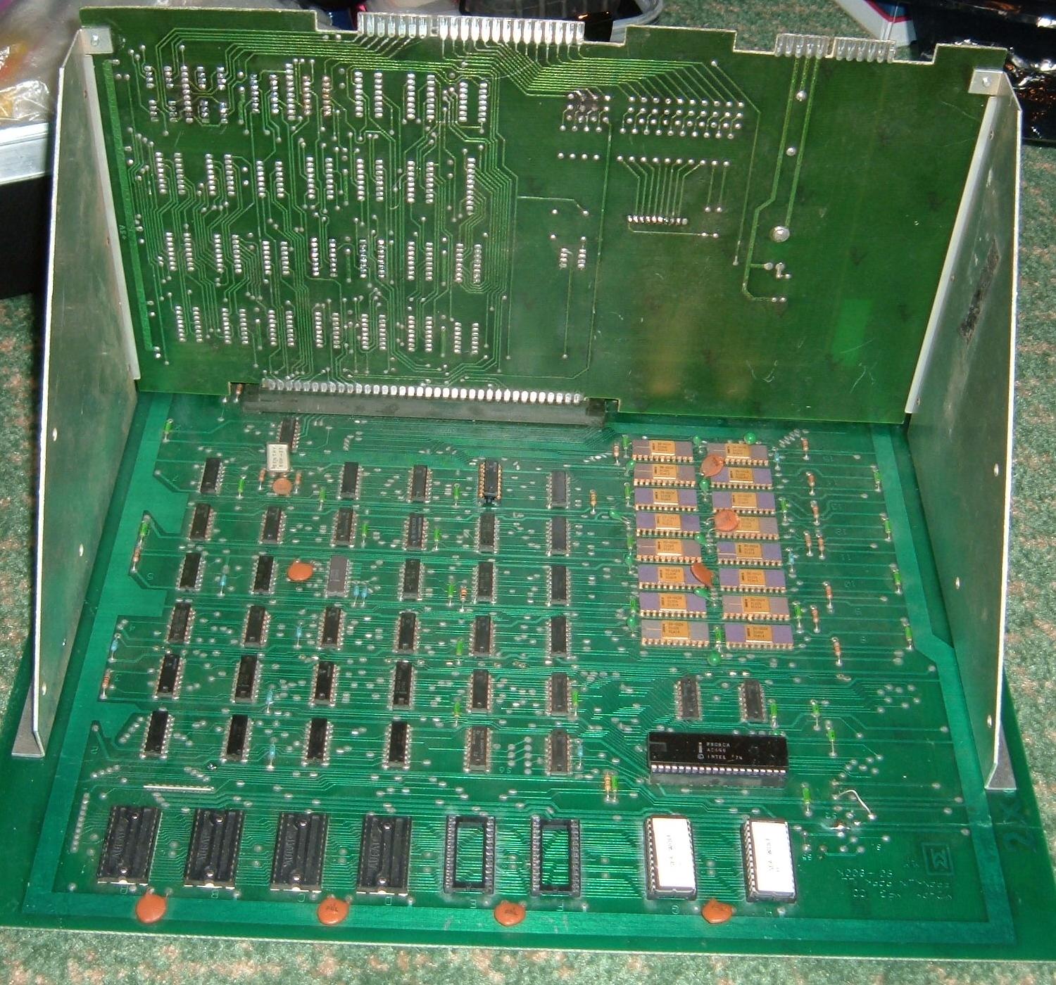
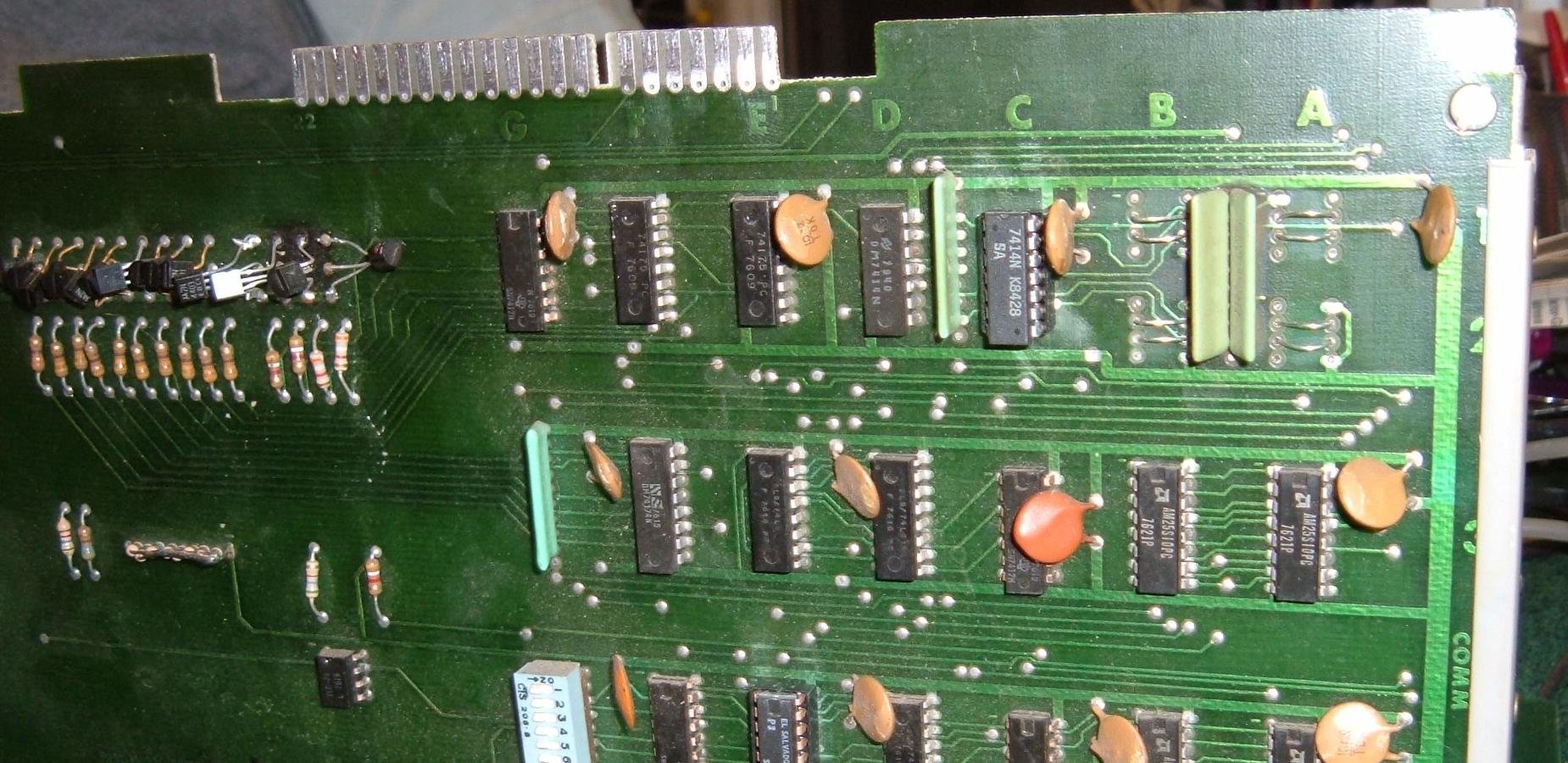
The "L" shaped CPU board used in Midway Sea Wolf, Space Invaders, GunFight.
This particular unit is from Sea Wolf, and has been modified to take two 2716 EPROMs
at ROM locations G and H. This replaces EIGHT 512 byte ROMs with two 2716 EPROMs.
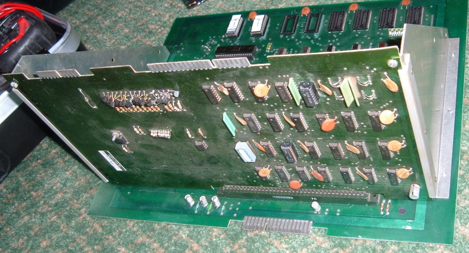
Here's the backside of the upright portion of the "L" shaped boards.
-
Modifying the CPU board for EPROMs.
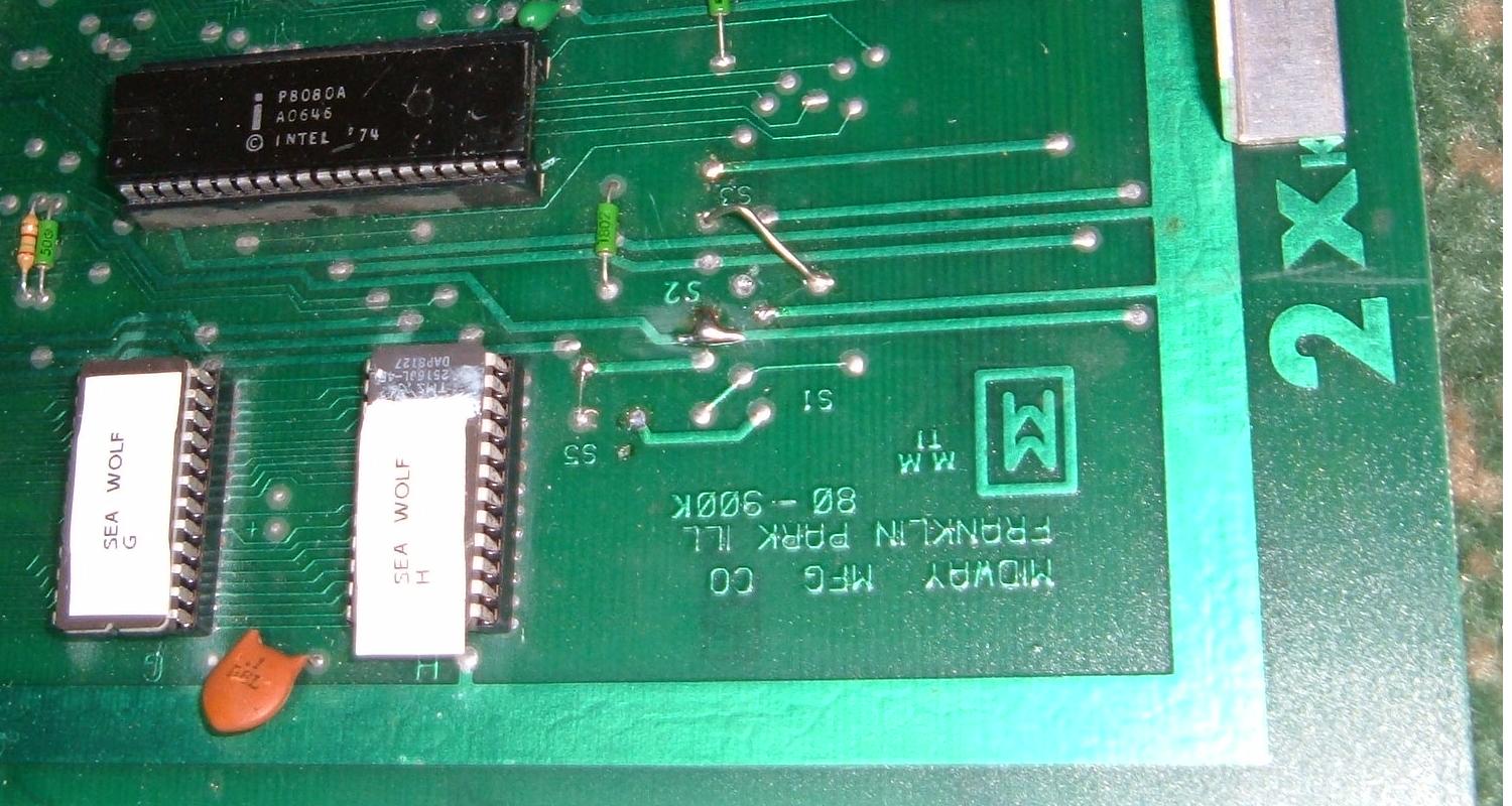
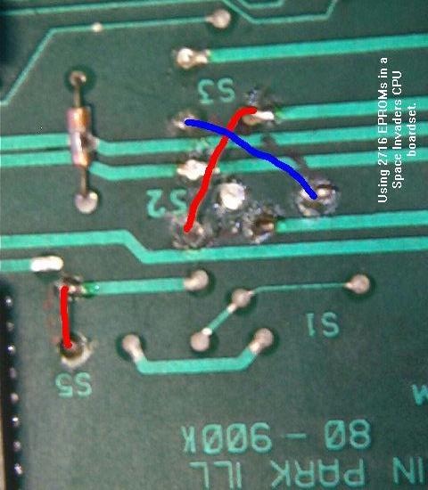
Midway gives about 10 different ROM jumper setting on this boardset. Unfortunately none of them are documented for the 2716 EPROM. Below are two pictures of this EPROM set up. Note Seawolf originally used four 2708 style masked ROMs, where Space Invaders used a 2716 style masked ROM. I'm not sure what Gun Fight uses. But you can't just plug in 2716 EPROMs and expect them to work, as the board needs some jumpers changed for EPROMs.
The jumpers needed for 2716 EPROMs on Sea Wolf. Note the soldpad jump at S2.
Also note the jumpers at S2 and S5.
Here's someone else's approach to EPROMs on a Space Invaders board.
This approach is nearly the same as above, except for the upper red jumper.
-
Opto Isolators.
Another potential problem is on the vertical part of the CPU board. At positions A and B across the top of the board there are two opto isolators. What these do is protect the boardset from bad or high voltage inputs on the control panel (like someone sorts higher than 5 volts to the control panel switches). If this happens, the ipto-isolators blow, saving the rest of the CPU board from damage. Great idea, but these opto-isolators are no longer available. Then can however be replaced with jumper wires, as shown in the pictures below.
Opto-isolators replaced with jumper wires at positions A and B.
Note the 2N3905 transistors at the top left of this board. These control
the periscope inputs on Seawolf. Often these transistors go bad and burn.
-
Power Supply
The power supply is critical to this game. Not only for the input voltages of +5, +12 and -5 volts DC, but also for the reset circuit on the power supply board. Below is a Space Invaders power supply, which will work in Sea Wolf and Gun Fight. The only difference is the Space Invaders power supply has pots to adjust the +12 and -5 volt power, where Sea Wolf only has a +5 volt adjustment.
Space Invaders power supply, component side.
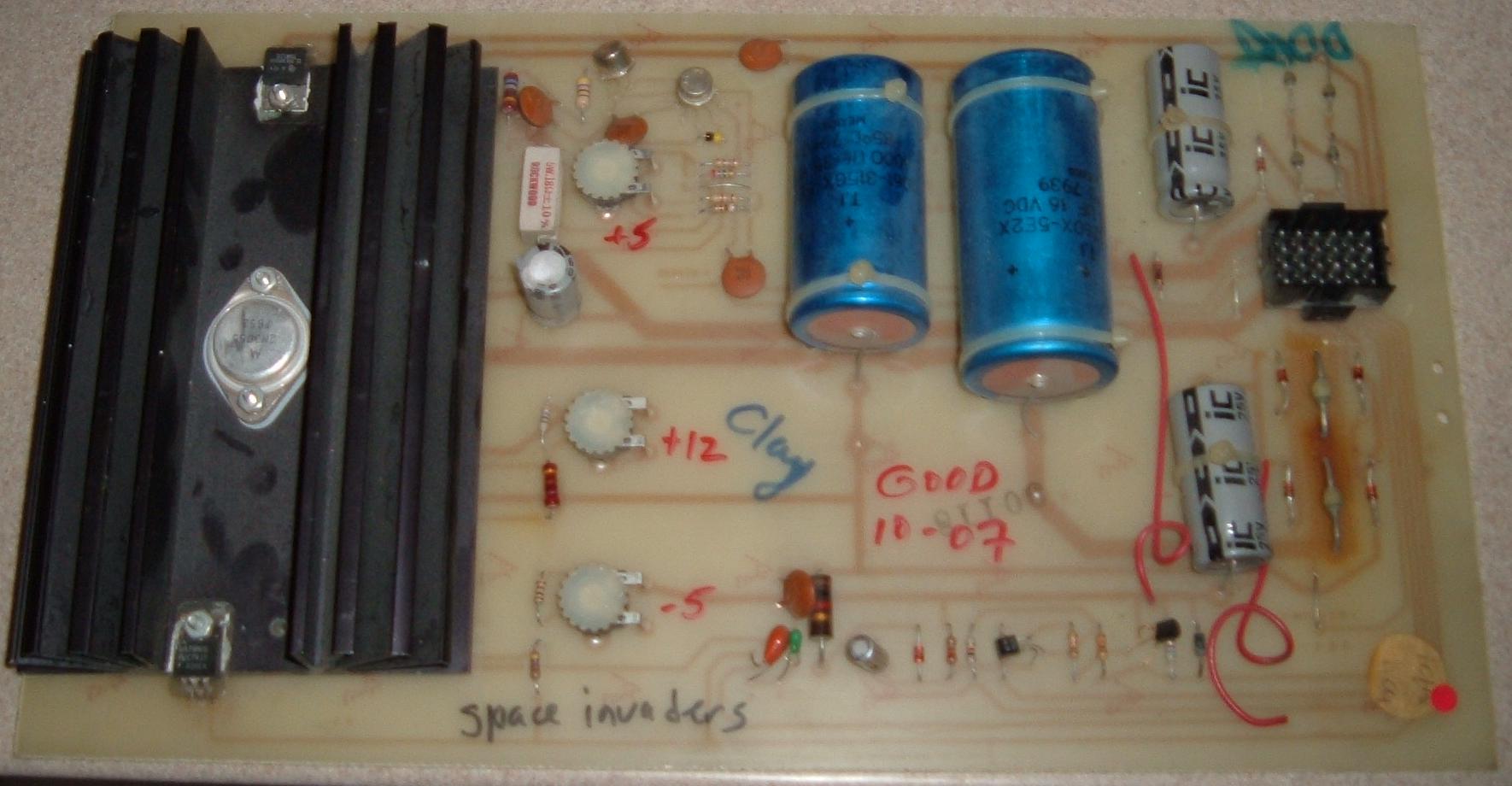
Space Invaders power supply, solder side.

-
Test ROM.
- sitest_716.bin = Location ROM H, size=2716 (chksum 461A)
- sitest_732.bin = Location ROM H, size=2732 (chksum 8C34)
There is a Space Invaders test ROM available here:
Depending on the strapping of your Space Invaders PCB, use either the 2716 ROM or the 2732 ROM. The 2732 ROM is simply a doubled image of the 2716. The Test ROM can be placed in location "H" without having to remove the other three ROMS. This can also be used in a Sea Wolf of Gun Fight game for testing its RAM.
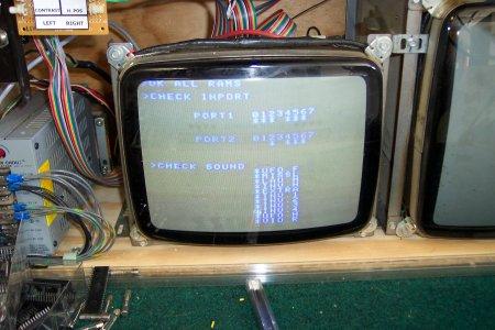
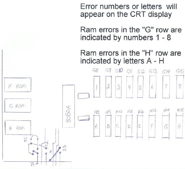
Once the Test ROM is installed on the game board, the Game goes through a small power up test somewhat like Galaxian but much shorter. If all RAM are good, a screen will be displayed stating "OK all RAMS", followed by another line stating "port 1" and next to it the numbers "01234567". Under that is "Port 2", and next to it "01234567". Port 2 appears to be the dip switch settings. An "x" can bee seen under the numbers for a switch that is on.
At the bottom of the screen there is a section that says "check sound" and an icon can be seen going down a list of 11 different sounds. A picture of the test screen is included below.
It is unclear if this ROM was intended to be used on the original Taito board, but it has been confirmed to work on the Midway PCBs. The ROM may work with the factory Midway board tester, but that has yet to be confirmed.
A monitor showing the test ROM running.
This chart shows the RAM error codes.
Return to the Marvin3m.com fix-it web page.
Contact the Author.