Description: Midway Table Tennis Wall Game, 1972.
Return to the general specifics for all Midway wall games here.
Please contact me if you have a Midway Table Tennis for sale at
cfh@provide.net
The following information pertains to the 1972 Midway Table Tennis in particular. Though this info can be applied to the other Midway wall games too. But I have personally added the following modifications to the Table Tennis model, so I know it works on that game.
Of all the Midway wall games, I would rank Table Tennis as the best of them. The Bullseye dart is the most popular by sheer manufacture numbers, but Table Tennis plays the best (with Golf Champ behind it, since it's different than that oh so common Bullseye dart game.) The trick to Table Tennis is accuracy. If you hit the ping pong ball just right, it returns the ball at super speed to your opponent, making it difficult for them to hit. It really makes for a super competitive interactive game (much more than the dart games, which lends itself to be more of a casual drinking game.)
Midway Table Tennis specifics.
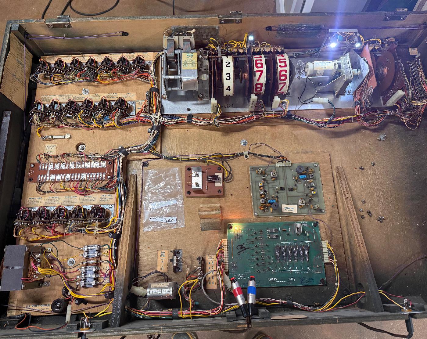
The Midway Table Tennis wall game is a bit different than the other Midway wall games.
One big difference is the use of a Motor Speed Control board. The other games do
not have this board. And if your Table Tennis game is missing this board, the
game will not operate.
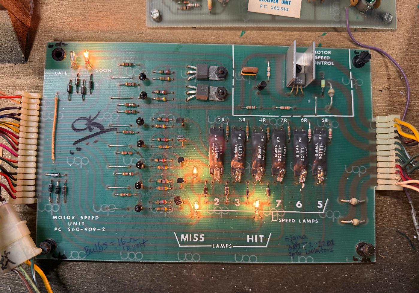
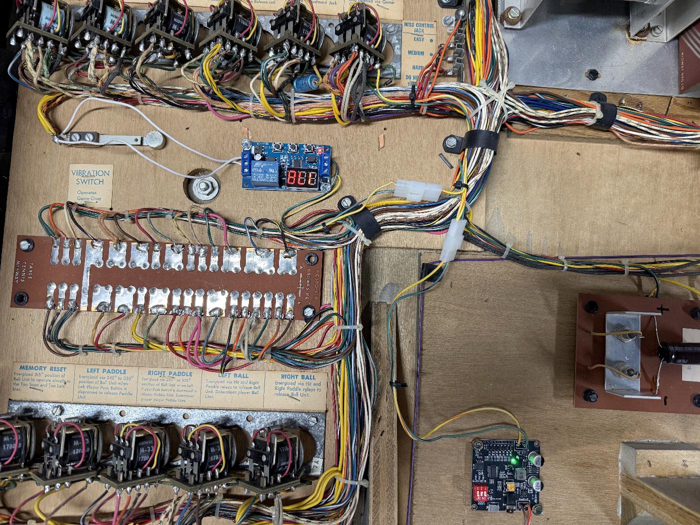
The motor speed board is very unique, using 2n5061 and c106 SCRs (like Bally -35 pinball games.) But the weird thing used is the Sigma 301T1-12B1 opto isolator. There are six of these, and they work in step with eleven 12 volt T3 style miniature incandescent light bulbs (about 16 ohms each.) Often these builbs either break at the solder point or burn out. If this happens, the game will not play properly. The light bulbs work with the Sigma 301t1-12b1 devices to trigger the SCRs, and varies the motor speed. This changes the ball volley speed in the game. If the board is missing or not working correctly, the game will not play.
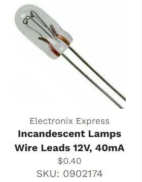 |
Note I have replaced the original 16 ohm lamps with new 28 ohm lamps from Electronix Express/RSR, part number 0902174. This incandescent lamp has wire leads and is 12v and 40mA at about $0.40, sku 0902174. This lamp is a nice size and easily fits onto the Table Tennis motor control board, and works nicely as a good replacement to the original lamps (where I can not read the original bulb number, and the schematics do not specify the bulb number.) If the original bulbs are not burnt, they often have the wire lead(s) broken, so they won't function. Bulb replacement is required if you want a working game. I tried to find a similar sized bulb with 16 ohms, and this is the best I found. But I'm sure other bulb(s) will work too, as long as they are 12v and have similar resistance. |
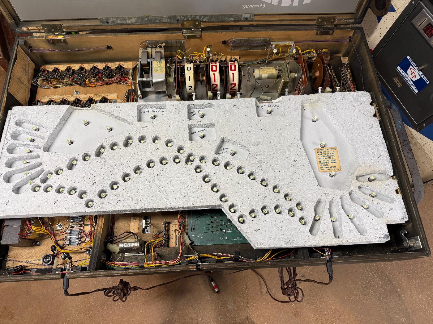
Using LEDs.
For the display lights mounted in the game's insert panel,
I converted to LEDs. Unfortunately pinball retailers do
not sell 12v LED bulbs in the 44/47 style bayonet format. Had to buy automotive
style LED bulbs instead. Which is fine, but they do not have a bridge rectifier installed.
Which means they are polorized. And unfortunately Midway did not pay attention to
how the lamp sockets were installed. Power needs to go to the base of the lamp socket,
and the "tit" needs to go to the control line. I had to reserve the wiring on
about 30% of my sockets so the non-polarized LEDs would work. But in the end, it
was worth it. The backglass lighting during play is much easier to see.
Replacing the Remote Controls.
These games often come up for sale, but are nearly always missing the
two remote controls. Also sometimes inside the game the RF receiver board
that reads the original remotes is missing or damaged. But no worries, for
about $30 you can make a new set of remotes.
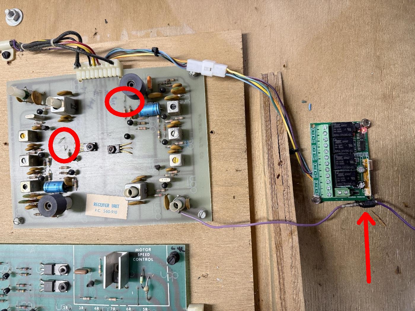
Amazon sells 12 volt Relay Wireless RF Remote Control Module with two 433Mhz Transmitter key fobs. With some wiring this can be used, and it works well. The original remote receiver board can be removed.
Note these new remote boards have four relays, but for Table Tennis, you only need the A and B relays. Train the keyfobs to your new receiver board (instructions included with the remote board.) Then connect the new receiver relay board's ground supply to the middle relay lug of the A and B relays. A seperate wire is then connected to each of the Normally Open A and B relay contacts. All this wiring (four wires) is connected to the existing original Table Tennis receiver board connector. I soldered the new remote wires to the back of the original receiver board. If you do this, should cut to the two 12v power jumpers on the face of the original receiver board, since you do not want any confusion between the two (possibly competing) receiver boards (new and orginal.) Also I routed the original purple antenna wire through the small coiled antenna wire on the new receiver relay board. This really seemed to help with keyfob reception!
For the wiring of the new receiver relay board, I used the original connector going to the original receiver board. It was just easier to tap into the game this way. On the original receiver board connector, the center yellow wire pin5 is ground, the two outside black wires pins1/9 are +12 volts. The A relay (left player) wire goes to the left player black/yellow wire (pin6), and the B relay (right player) wire goes to the right player red/white wire (pin4). Now when the game is played, the keyfobs are the players' triggers. You can mount them is a larger box, which is a nice touch (see below), because playing this game with a keyfob kinda sucks (and they are small enough to loose easily.)
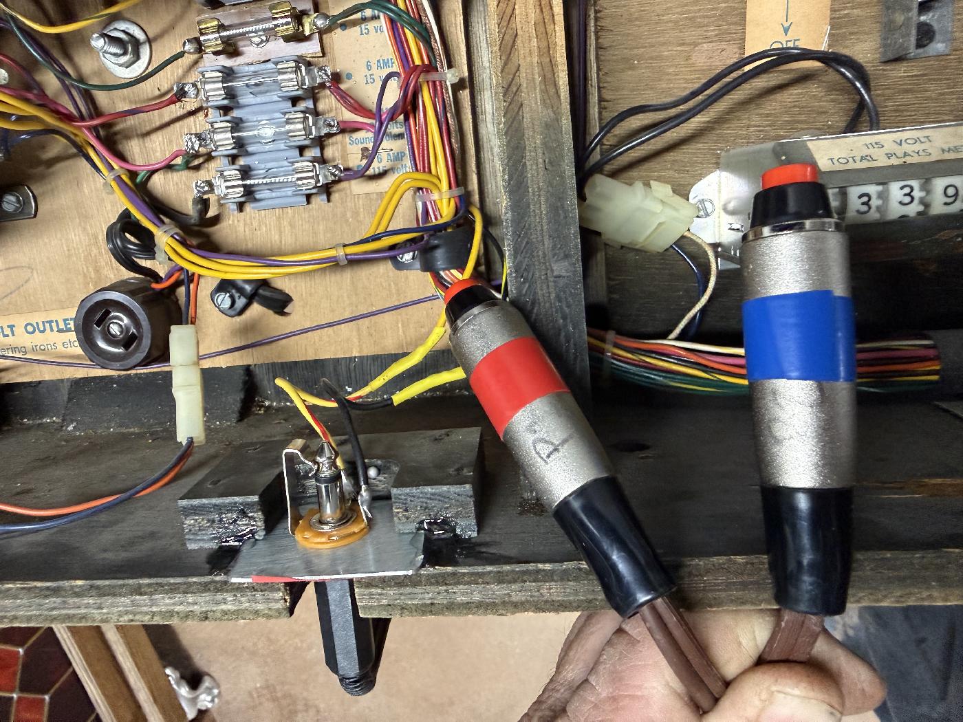
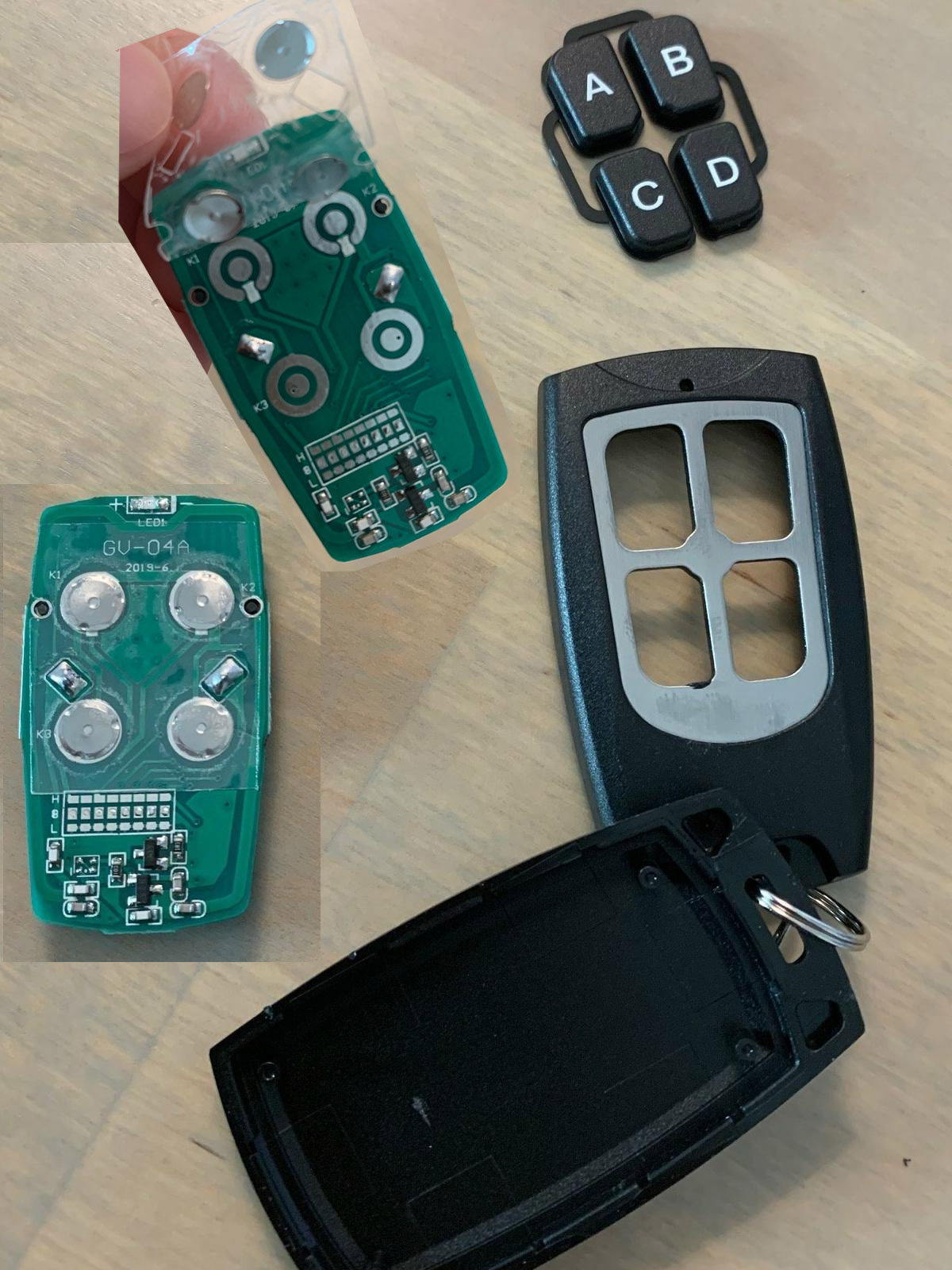
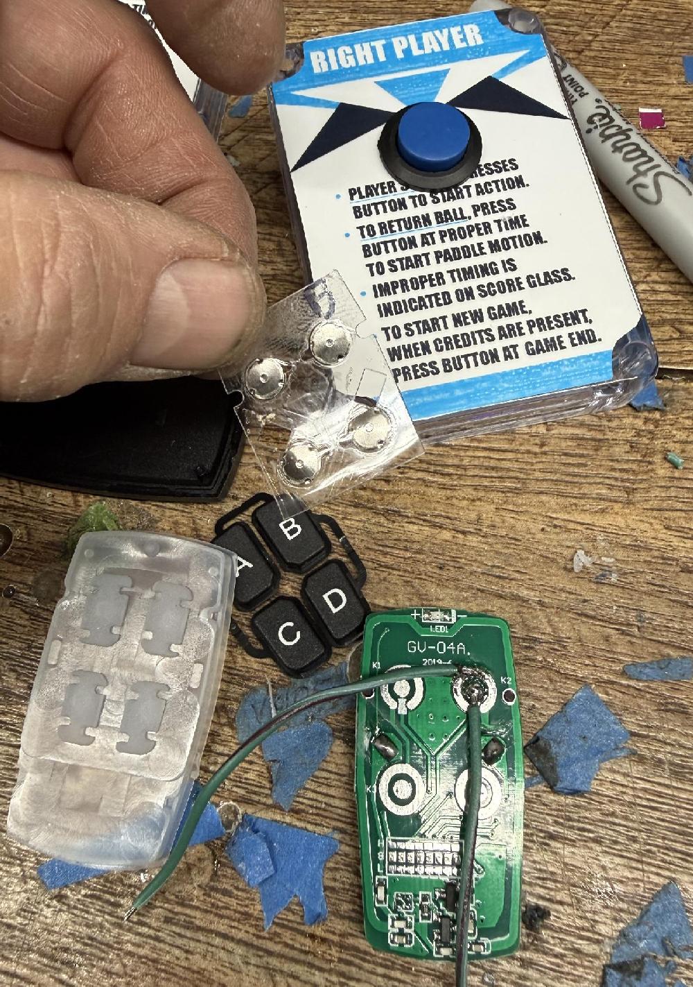
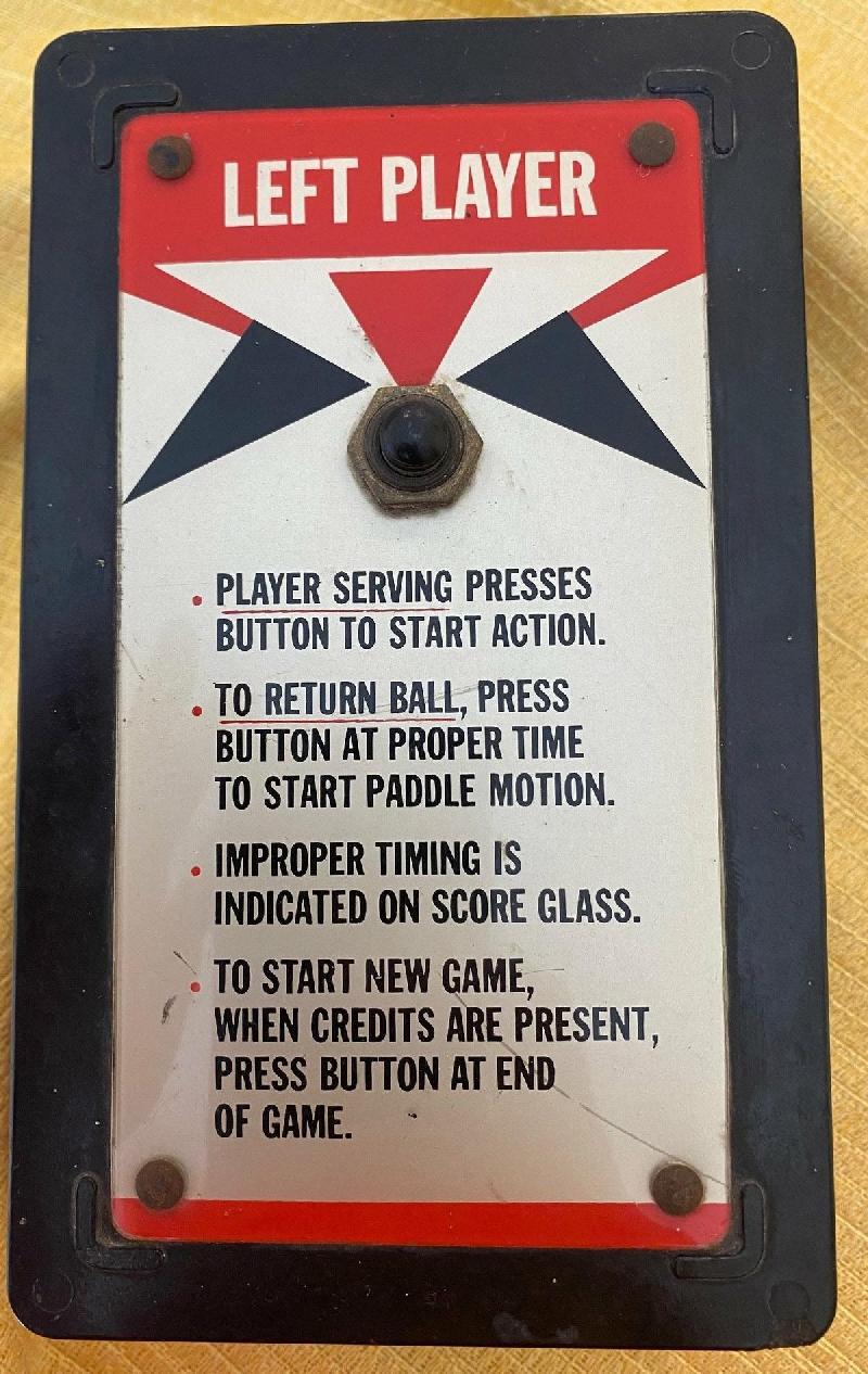
Remote boxes can also be purchased on Amazon. Drill a hole for a momentary switch in the face of the box (drill slowly, the boxes can crack if you drill too aggressively.) Take the remotes apart, remove the metal button film from the remote circuit board (it's taped in place), then solder two wires to the "A" contacts (for Left player), and the "B" contacts (for Right player.) Mount the remote boards in their respective boxes and you now have two new player remote controls for the game. I have also created some Photoshop graphics for the Table Tennis remote boxes.
On this game (and only Table Tennis from what I have seen), the Left and Right player buttons *also* triggers a new game (assuming the game is over and there are credits, which if you did the free play mod, there are.) Hence if power to the remote receiver board is always on, pressing either the left or right tennis button will start a game. That's why I did not use the Lock relay power setup for the new remote board (which only provides power during game play.) But if you don't want that feature (that is you want to force the players to press a 'start' button), wire the remote board to the Lock relay power (instead of using the original receiver board yellow/black wires for power.)
Adding a Timer.
One of the problems with these Midway games is if someone starts a game,
and walks away, the game keeps running forever, and the score reel motor keeps spinning.
With non-Midway games or pinball games,
that's generally not a problem. But on these Midway games, the score motor will continue
to run. And it could get hot and burn. Replacing/rebuilding a burnt motor is time consuming
and frankly a lot of work. I have tried installing a thermal
switch on the motors, which is a good idea, but that's not the best solution.
Another better idea that is more elegant is adding a timer board.
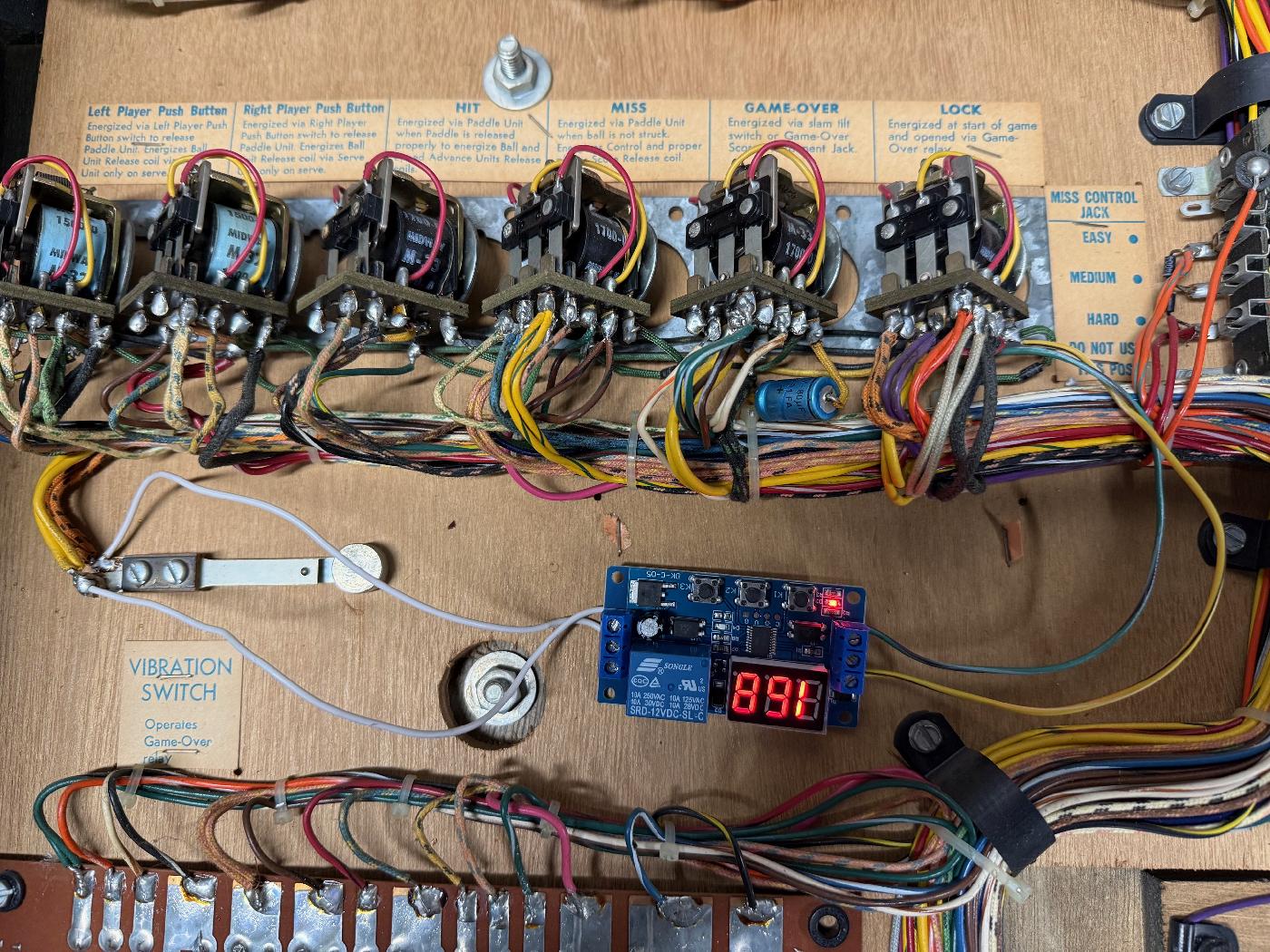
I bought a Timer Board on Amazon for less than $10 and found it works quite well. It powers at 12 volts (or 4vdc to 20vdc.) The timer board use the power stream from the Lock relay power. This way, the timer board turns on right when a game is started, and counts down. After the set time, it Slam tilts the games, turning off power to the timer board, and of course ends the current game.
I tried a couple different timer boards, and the one i liked best was more programmable and had a nifty countdown LED. This way could program the board to 180 seconds. Then after this set time, or to the specified number of points to win (Midway Table Tennis selectible from 4 to 8 points), the game ends. The timer relay's Normally Open switch is connected to the Vibration Slam switch. After 180 seconds, the timer board's Normally Open relay switch closes and slam tilts the Vibration switch, which ends the game. This works really well. The COM and CK leads of the relay are just connected to the slam switch lugs. And the VCC goes to the Lock relay's banded diode lug (12v), and GND to the Lock relay's non-banded diode lug.
I have found that two minutes is a bit short, and set it to a three minute game. This timer addition is a great way to avoid risk for 50+ year old motors. Because someone starts a game and walks away, these Midway games can self destruct. And repairing/replacing those motorized score reel motor(s) is a job that no one should want to do.
Adding an MP3 background sound track
This is obviously completely optional. But I like having a background sound (the only stock sound
is the knocker coil hitting when a volley is completed.) The other advantage to a background sound
is making it more obvious a game has started. Because Table Tennis has the ability to start a
game by pressing either Left/Right player switches, it just makes it obvious a game is starting.
Because this game uses 12volt DC as it's main power source, the MP3 player used must also be powered by 12vdc. I found the best/cheapest solution to be a Pemenol GY16922 (DY-HV8F) mp3 player (documentation available here.) Using the Lock relay's power buss (much like we did for the timer board), the mp3 player will start playing as soon as power is applied (a game is started.) But we need to set the mp3 player to autoplay a 00001.mp3 pingpong sound, or also 00001.mp3 popcorn sound. These are over 3 minutes long since the timer board is set to 3 minutes. The sound files are saved on the mp3 player's onboard RAM, and are added to the board much like a USB stick (you'll need a cable connected from the mp3 board to your computer's USB port.) There's a DIP switch which should be set to standard mp3 mode of "on off on", with the single sound file named 00001.mp3. This way the board will power up and start playing 00001.mp3 song (or any mp3 song you desire.) Obviously you'll need to add an 8 ohm speaker somewhere in the game. And upon game start, just like the timer board, the game will play the background sound, and turn off sound at game over.