Repairing Electro-Mechanical (EM) Pinball & Coin Operated Games to 1978
Part Two
All text and pictures copyright by cfh@provide.net (Clay Harrell),
01/30/25. Copyright 1998-2025, all rights reserved.
Scope.
This document is a repair guide for Electro-Mechanical (EM) coin operated
games made up to about 1978. This includes pinball games, pitch and bats (baseballs),
bowlers, gun games, etc. Though pinball is stressed the most in this document, this information
applies to most EM arcade games made from the 1930s to 1978.
Electro-Mechanical (EM) means the game uses relays and switches,
and does not use a computer CPU.
This document is geared towards complete beginners.
No experience is assumed, though basic electrical knowledge is
helpful. The document should be read "top down" and in
its entirety. (Well at least up to, but not necessarily including, part 3.)
Updates of this document are available at
http://www.pinrepair.com
if you have Internet access. This document is part two of three -
part one is here,
part three is here.
2a. Before Turning the Game On: Check the Fuses and Fuse Holder
Seems like such a simple thing, yet many of us forget to do it.
Before you even turn the game on, check the fuses. Not only look for
blown fuses, but over-fused circuits. For example, is there a 25 amp fuse
where there should be a 10 amp?
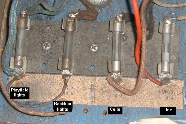
There are at least four fuses for any EM pinball game.
One for the line voltage, one for the solenoids, one for the playfield
lights, and one for the backbox lights. There may be more (depending on
the game). Often there are fuses located else where too, like on the
bottom of the playfield. There's usually a fuse for the
the reset bank, and sometimes elsewhere for other features
like a fused bridge for AC to DC power conversion for pop bumpers.
Testing Fuses: the Right Way.
Don't depend on eyes or sense of smell to check fuses. A perfectly
good looking fuse could be open, it happens all the time. Fuses can
go open because of age (fatigue) too, and not just from shorts or
over current. Use a Digital Multi-Meter (DMM) to test fuses.
First remove the fuse from its holder.
This is important, and applies to Solid State games too. Don't try
and test the fuse installed! The reason? When removing the fuse you're testing
the fuse's structural integrity and you're also testing the fuse holder.
So remove the fuse from its holder.
Now Set the DMM to "continuity", put a lead on each
end of the fuse, and buzz out those fuses. No buzz means fuse is bad.
(This of course assumes your DMM has a buzz continuity feature, which most do.)
Side Note: a "buzz" on the meter means zero resistance. If no
"buzz" is heard, either the circuit is OPEN, or the resistance is 100 ohms
or greater. If the meter doesn't have a continuity function, just use
the lowest resistance setting. A good fuse will measure zero ohms.
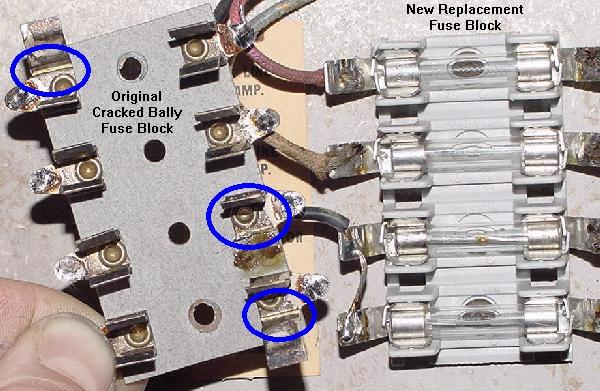
Fuse block on a Bally Fireball. Bally fuse holders often need to be replaced
as the metal clips fatigue and crack.
Left: a Bally fuse block with cracked fuse holders. The stress cracks can be seen.
Right: a new replacement fuse block.
Fuse Holders.
Often the fuse holders on EM games are tired and have lost their "spring".
This will cause a bad power connection. Symptoms include missing all lights
on the playfield or backbox, all coils don't work, or a game that just
won't power on. This is very common on Bally games. Often
the fuse holder's tabs can be bent for a better connection, though sometimes the tabs
will break doing this. Keep a stock of new fuse holders around and replace when needed.
Also clean the fuse holder. These can be so dirty, the fuse won't
make contact to the holder. Dirty fuse holders can also cause resistance,
and the heat generated can cause the fuse to open (blow).
Use a small wire brush to clean the fuse holders.
What Causes a Fuse to Blow?
The first thing to figure out is what does the blown fuse
control? Is it the 6 volt lighting fuse? (Note sometimes there
are two 6 volt fuses, one for the backbox, and one for the
playfield.) Is it the solenoid fuse? (Usually 30 or 50 volts.) Or is it
the 120 volt line fuse? Also on some EM games there is a
selenium or bridge rectifier or diode(s) and an associated fuse for
that (this is common on 1970s Williams and Bally pinball games and
1950s Genco games).
The first thing to do is clean out all the lose parts in the bottom of the cabinet by hand and save it.
Then vacuum all the crap out of the inside
of the game. It amazes me what you will find inside an old game,
and often when the game was moved, this junk can lay across some
wires or contact points and cause a blown fuse.
So vacuum the bottom of the game (but
save all the parts you find, including loose nuts and bolts).
Once you know which fuse is blowing, it makes things a
bit simplier as you only have to look at that circuit
to find the short.
120 volt line fuse blowing: look for a shorted power cord
or a shorted transformer (rare.)
6.3 volt backbox or playfield lighting: usually two fuses
for this (backbox, playfield). Sometimes
bulbs short (rare, but it happens). More often it's a playfield
light fuse, as a bulb holder gets bent and shorts.
30/50 volt solenoid voltage: this is the most commonly
blown fuse. It powers all the coils and the score motor.
If a coil is locked on, this fuse will often blow. Or on games
with AC to DC power conversion for the pop bumpers, the bridge rectifier
has shorted.
Use a Small Circuit Breaker.
As shown in the Tools to Have on Hand
section, a small circuit breaker is really needed to diagnose
any blown fuse problems. Otherwise you might as well buy
stock in a fuse company while you diagnose this problem!
Fixing a Failed Lamp Fuse.
If the game is blowing a 6 volt lighting fuse, that is often
caused by a shorted light bulb or light bulb socket. Or a wire
for the GI (general illumination) is touching the metal frame
of the game. This will of course blow a fuse, and these problems
can often be hard to find.
Look under the playfield for a lamp socket that
has the "tit" bent over accidentally and is touching the
"base" of a lamp socket. This is common on lamp sockets on the
edge of the playfield, because the playfield can be accidentally
lowered at a slight angle bending a lamp socket. Also if you
took all the parts off the top of the playfield to clean it,
check all the lamp sockets in case something metal fell inside
a socket.
As described in the "tools to have section" of this document,
the easiest way to find a light short is to make a "cheater" using
a small circuit breaker. Take a blown
glass fuse, and solder the small circuit breaker to the ends of the fuse.
Now insert the fuse into the game
and turn it on. If there is a short, the breaker will 'blow' and can be
reset. This makes finding the short in the GI
circuit A LOT easier (and cheaper since you're not replacing the
fuse multiple times.
Now to find the short.
It's a good idea to do a visual inspection of each lamp socket. Remove
all the light bulbs too (you were going to replace them all with
new #47 bulbs anyway, right?) If the fuse stops blowing with all
the bulbs removed, then there was a shorted bulb. Replace the
bulbs one at a time with the game turned on to find the culprit (or just
install new bulbs). Sometimes flashing #455 bulbs can short too.
If the light fuse still blows with all the bulbs removed, there is
either a shorted socket, or maybe a short at a connector (see the
section below on connectors).
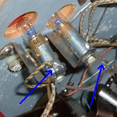
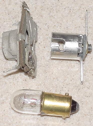
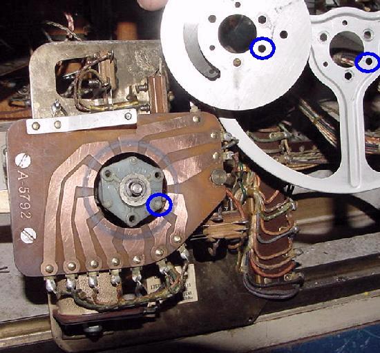
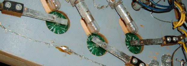
Here's an example of a shorted lamp socket. The socket on the left
(shown by the left blue arrow) has the "tit" connection shorted to
the frame of the lamp socket. The bulb on the right shows a lamp socket
with a correct configuration.
Now I break the circuit down into sections. That is
I cut the GI wires as they enter the playfield (in the case of a playfield
short, with the playfield standing up and against the backbox, cut the GI circuit
at the first set of sockets at the "bottom" of the playfield.)
Now power on. If the fuse does not blow, I add 10% to the string
and re-attach and re-cut (adding some more bulbs.) Keep doing this until the short is found.
Again having the circuit breaker tool is mandatory for doing this,
unless you have a infinite supply of fuses.
Yes this takes time, but there really isn't any other way.
Solenoid Fuse Blowing.
If the 30 or 50 volts solenoid fuse is blowing,
this can happen from a
low resistance EM coil (please see
that link for more information). Also on pinball games,
if the flipper coil's EOS (End of Stroke) switch is not adjusted correctly, this can
cause the solenoid fuse to blow. See the
flipper coil explanation section above
for a description of how the flipper coil and EOS switch work
together (but basically the flipper EOS switch should open when
the flipper is fully energized; if it doesn't open, a burned flipper coil and/or
blown fuse will result.)
Check the playfield switches and make sure none are stuck closed.
Then examine all the coils for any burnt coil wrappers
(a sign that the coil has been on for too long). You can
use a DMM and measure the resistance of any suspect coils (see
low coil resistance for details
on this). Most often bell, chime, knocker, flipper and 00-90 unit coils seem
to be most problematic in this regard.
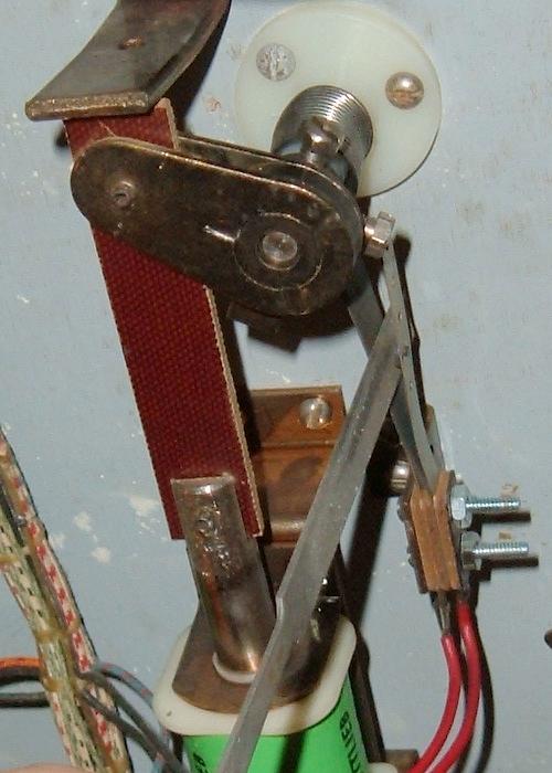
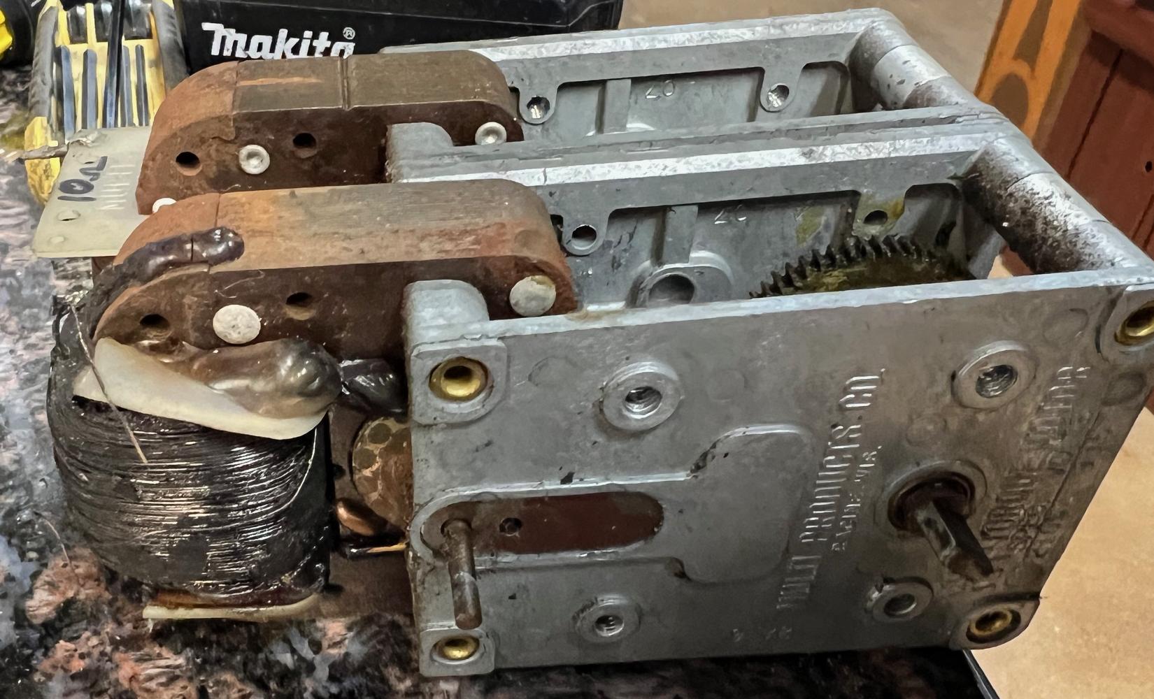
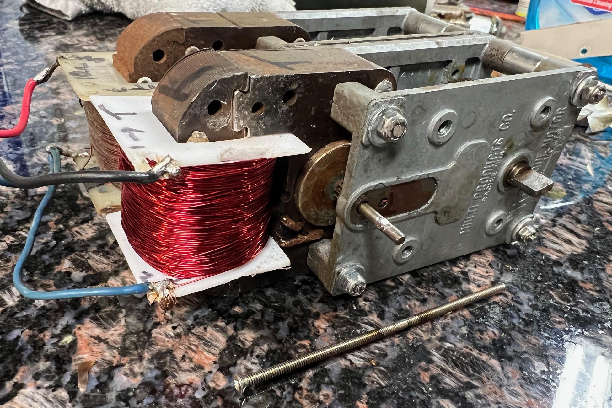
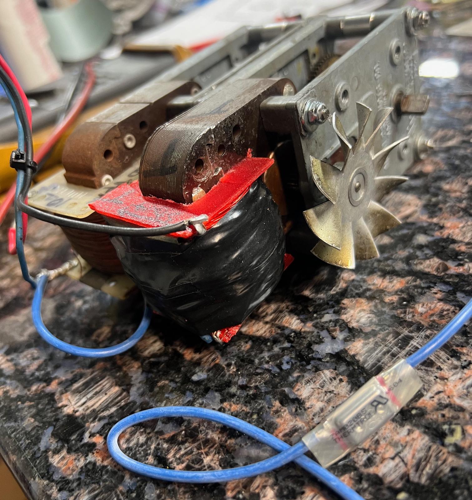
Here's a heat stressed flipper coil. This often happens due to a mis-adjusted
EOS (end of stroke) switch on the flipper assembly. The resistance of this coil
should be checked before re-installing.
Check Coil Resistance.
Low resistance coils will blow the solenoid fuse.
Any coil that looks heat stressed (has a charred wrapper) should either be replaced
or at least have its resistance checked. I have a table of common
coil resistances in this document here.
But usually anything below 2 ohms is a bad coil. Just put your DMM
set to low ohms and put the DMM leads on the lugs of a coil. This
will give you the resistance. Three lug coils are a bit more involved
to check, as they are two coils in one package. But usually the middle
lug is "common" and the outside lugs can be checked. (Note on a 3 lug
flipper coil the EOS switch needs to have a piece of paper between the
switch contacts to get a good flipper coil resistance measurement.)
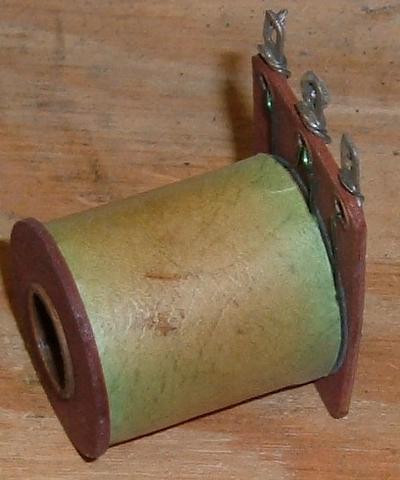
Bally Fireball's "Lock" relay coil, which is obviously heat stressed.
This relay coil is not bad, but it's on the way to self destruction.
Relay coils should also be checked for resistance.
In particular the "Lock" coil on EM games loves to burn,
as it's on all the time. Also the coin door lockout coil
(which is not needed unless you're running money through
the game) also likes to burn. (I recommend disconnecting
the coin door lockout relay as you'll be running your
game on free play, so it's not needed.)
Gottlieb coil door lock out relay. These almost always burn, and should just
be disconnected. They return the coin to the player if money is inserted into
a powered off game, or a game that has the credit unit maxed out.
Other Fuses.
Also on (primarily 1970s Williams and Bally) games with
selenium or bridge rectifier or diode(s), these can short and
blow its accompanying fuse. Starting in 1972, Williams changed their pop
bumper and slingshot kickers to operate on DC voltage.
Bally also made this change in 1976.
To do this, Williams and Bally used a silicon Bridge Rectifier.
Unfortunately, sometimes the bridge shorts internally, and
will blow the solenoid fuse when a game is started or when
a pop bumper/slingshot coil fires. Please see
When things go wrong for more
information on fixing this.
Gottlieb also used 1 or 2 amp slow-blow fuses to protect the reset
coil(s) on large (under the playfield and bottom panel)
reset banks.
2b. Before Turning the Game On: Jones Plug Connectors Cleaning & Dim/Bad Lamp Sockets
Over the years, I have seen the EM game connectors (aka Jones plugs) get worse
and worse in condition. In the past my response to cleaning them has been,
take 400 or 600 grit wet/dry sandpaper
and dry sand the circumference of the male side of each pin of the plug. This is
the area that the female plug bites in to. Wrap your sand paper around
each pin, and rotate a few times. They don't have to shine like a new
penny; just get the major crud off.
Unfortunately, as time has marched on, this technique is proving to be
less viable. The connectors are just getting worse in condition, and simple
sanding is perhaps not enough.
A Gottlieb pin style connector after a quick cleaning.
This pin style connector is the most common EM connector.
Alternatively a small stainless steel wire brush can be
used (both in the long and short directions of the male connector pins) to
shine up the male pins. (Personally I use a wire brush instead of sand paper
as it's quicker.) This works really well. Wire brushes are available for about
$2 at Home Depot in the welding department (get the stainless steel variety,
not the brass brushes.)
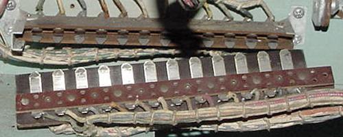
This flat style of connector is usually just seen on some Williams games.
These are real easy to clean, but generally this is not as robust of a
connector as the pin style.
More Elaborate Cleaning.
Some Jones plugs, over time, need extreme measures to conduct
consistently. Usually you can just look at the male pins and see
bad corrosion. Sanding or a wire brush won't cut it. Instead using
a variable speed Dremel with a stainless steel brush is the best
course of action.
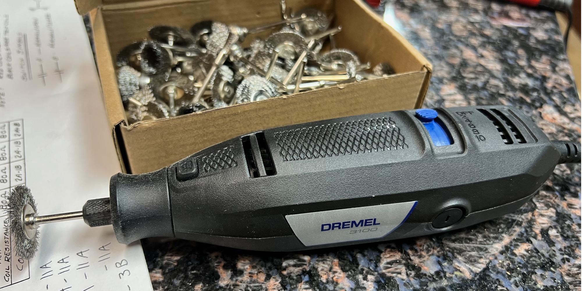
Speed kills with a Dremel and a stainless steel brush! I like the Dremel 3100
variable speed model, and going as slow as possible, to clean the male Jones plug connectors.
But be careful when using the Dremel. You *must* have a variable
speed Dremel, and you must run it at the lowest possible speed
that gets the job done. Why? Because speed kills with a Dremel.
It will throw the metal stainless steel hairs, and if one hits you
in the face or eye, you will be sorry. The metal hairs stick to
your clothing too, and frankly they hurt. Also the metal Dremel
brush are not cheap, and will kill themselves quickly if you use
too much speed.
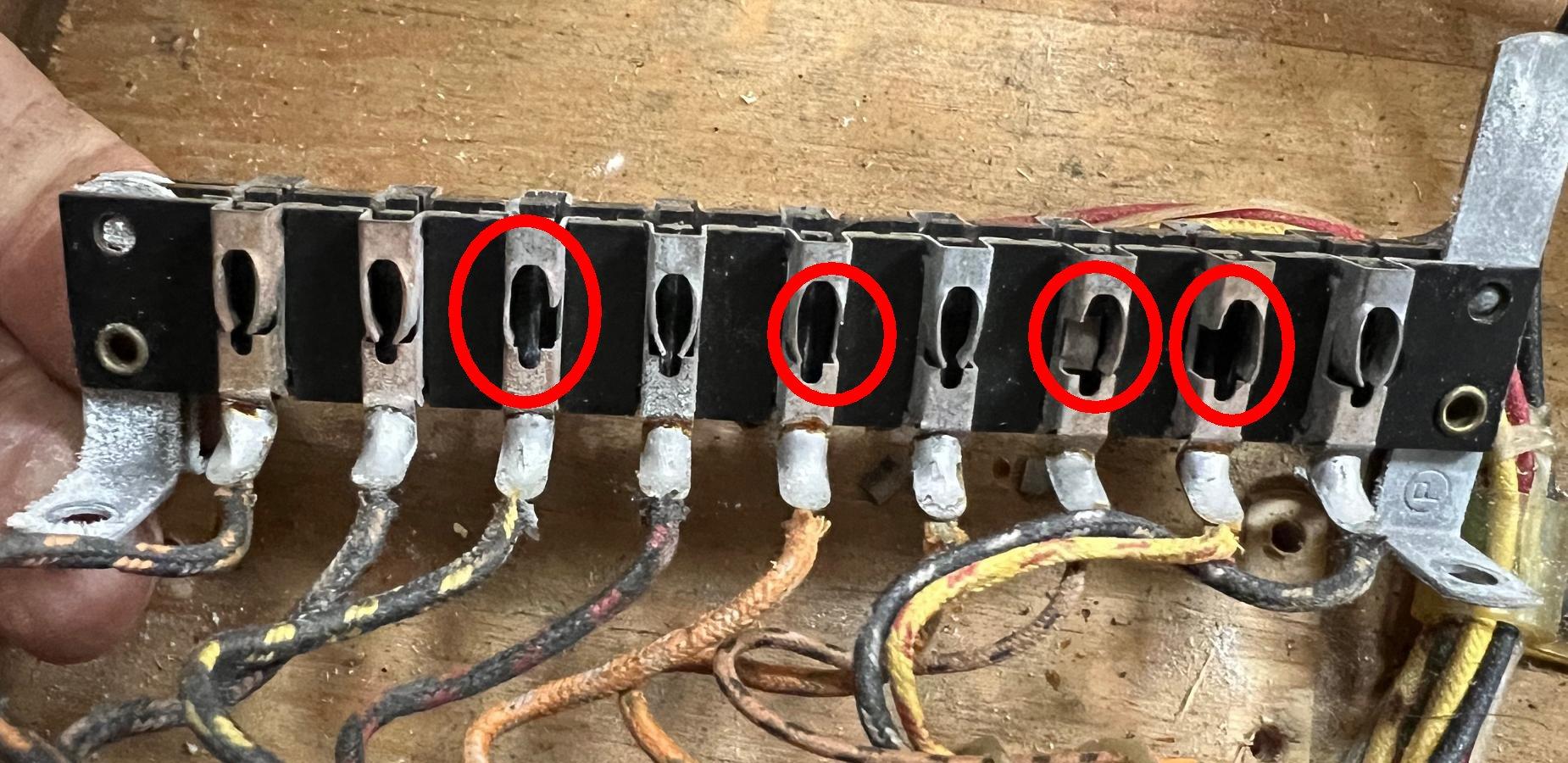
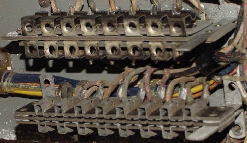
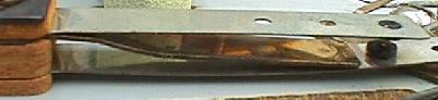
The female Jones plug connector on a 1964 Williams Heat Wave. Total collapse of
the contact points, where they have just broken. This connector is not saveable.
The only alternative is replacement with another used female Jones plug. Unfortunately
new Jones plugs are not available...
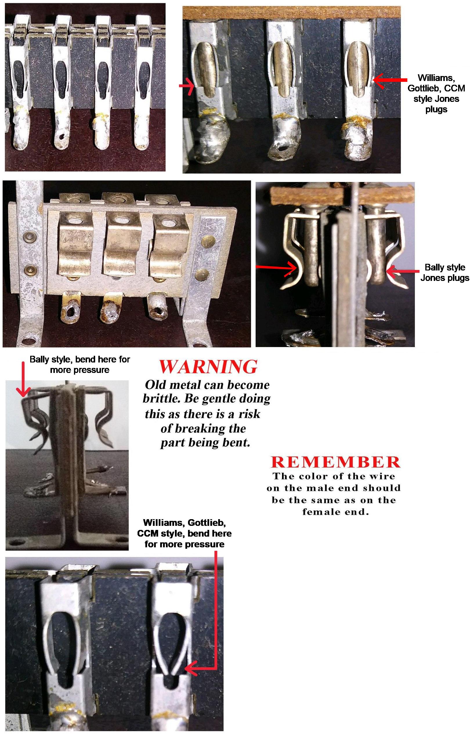
Only clean the male side of the Jones plugs with the Dremel. I have
seen some people trying and clean the female side, but often that
ends in damage to the connector. A better approach on the female
Jones plugs is to retention the female side. See the picture below
for help with this. But on Bally male Jones plugs, the contact points
are on the *outside* of the male pins. On Williams, Gottlieb, CCM
the contact points are on the *sides* of the male pins. Make sure
you pay attention to this, because cleaning the wrong areas does not
help your cause!
The Jones plugs used in Bally games are different than those in Williams, Gottlieb, CCM games.
The contact points are different. Make sure you clean the male pins in the right places,
and retention the female side correctly too.
Examine the Male Connector Insulation (that has pushed back.)
Often the insulation on the wires going to the male connector
pins has shrunk or is pushed back. This can cause the bare wire to
short against an adjacent connector pin or wire. If this happens,
a blown fuse is the likely result (in addition to some function
of the game not working). To fix this, the
tip of the connector pin will need to be heated
with a soldering iron, and the wire
pushed further inside the pin (add some solder to the wire end of
the connector pin too). Also check for broken wires on the male plug.
And finally look at the bakelite material that holds the pins.
Sometimes these crack and break. If this happens, there isn't
much that can be done except for replacement (though sometimes
the bakelit can be reglued with Super Glue and some scrape pieces of
bakelite glued to the flat areas.) Bottom line, just don't break them!
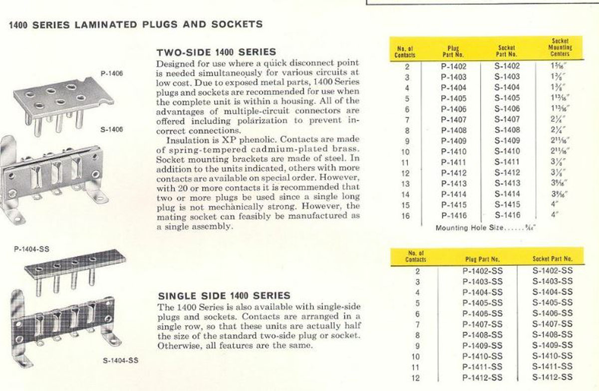
Jones connectors sales data from long long ago...
Bally Connectors.
Bally connectors are particularly troublesome. For some reason,
Bally decided to make their own connectors, instead of buying them
from an established connector company. Hence Bally connectors are
low quality in comparison. This causes particular problems, as
the female portion of the connector can metal fatigue, not providing
proper tension to the mating male pins (or worse yet, the female
tension pins can break). The male portion of the Bally connector is fine,
it's just the female part that breaks. For this reason, I don't suggest
"reseating" Bally connectors in an attempt to fix a problem! Each
"cycle" of a Bally connector is one step closer to connector death.
Fortunately only Bally connectors are fragile; Gottlieb and Williams
used better connectors with less problems.
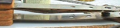
Top: a Bally female pin connector.
Bottom: a Gottlieb/Williams female pin connector.
The only way to repair a broken female Bally connector is to
replace it. Since these connectors are not available new,
an old Gottlieb or Williams parts game can be used as a donor,
and the female Bally part replaced.
Another common problem with Bally connectors is the tilt assembly
mounted connector. This brings 6 volts from the transformer to the
fuse block on Bally EMs that have the fuses mounted under the left
flipper button. This connector (as used on Captain Fantastic, 1976)
just loves to burn, causing the GI (general illumination) for the
playfield and/or backbox to not work. There isn't much you can do
to fix this - just cut the wires on the male and female side of the
connector, and splice them together. This connector is pretty useless,
and isn't needed to disassemble the game (or even to remove the coin door.)
So going around the connector to remove the burnt GI connector pin is
an OK idea.
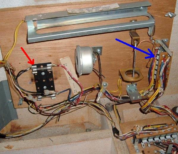
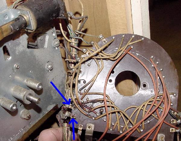
Bally Captain Fantastic: the connector mounted on the tilt assembly
is particularly troublesome on Capt. Fantastic. This connector (blue arrow)
brings the 6 volt GI (general illumination) circuit to the fuse block, and then
back out to the rest of the game. Often this connector burns, causing all
the GI lamps for the backbox and/or the playfield to not work. (On this game
you can see the fuse block was modified, making the GI problem worse, red arrow.)
Gottlieb Coin Door Connector.
It's also a good idea to clean the connectors that attach to the bottom
panel of the game, and the coin door connector. Gottlieb coin door
connectors are especially important - If this connector is not making
good contact, the game will refuse to work, or some feature will not work!
Dim and Failing Lamp Sockets.
Though bad lamp sockets aren't going to make a game not work,
they are really annoying. Lamp sockets are made of metal and
a fiber insulator. They are pressed together to form an air
tight seal against the parts. But as time marches on, the fiber
insulator shrinks, and air (humidity) gets between the parts. Corrosion
comes, and the socket becomes intermittent or doesn't work
at all. Often playfield lamp sockets can be repaired, but really the
best solution is to replace faulty sockets. Backbox sockets
(the lamps behind the score glass) can almost never be repaired,
and must be replaced.
Because there are so many different types of lamp sockets,
I personally try and repair them opposed to replacing them.
Also the price of lamp sockets has gone up dramatically in the
last few years (what was 20 cents is now approaching $1 each.)
Again I find repairing a socket is easier, faster, and cheaper than
replacing them.
Many people buy rubber "pencils" and use those to clean the inside
of the socket. I rarely find this to be a problem. The bigger problem
is the socket is "loose" (because the fiber insulator has shrunk.)
But if you do decide to clean the inside of the socket, if you put
that rubber "pencil" in a variable speed cordless drill, you can clean
the inside of a socket in about 5 seconds!
Some people like to use Dow Corning DC4 silicon grease inside dim (failing) lamp sockets.
Personally I do not like this approach, as you are trying
to fix a MECHANICAL problem with a CHEMICAL. I just don't think
it's a good idea. But in DC4's defense,
unlike general purpose grease, it has very low film strength and
keeps moisture and air from making contact with the metal to metal electrical
contacts.
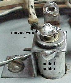
"Fixing" a playfield lamp socket.
The wire that powers the tip of the bulb
is moved directly to the tip of the socket.
The base of the socket is then soldered
together so it can not rotate. Be sure to
sand the parts before soldering, and to use
some Rosin flux on the socket.
Fixing Lamp Sockets.
To really "fix" a socket, you need
to repair it mechanically. Get some 220 grit sand paper,
and it's not a bad idea to have some rosin solder flux too (though I
rarely use it, it is helpful.) First I want to solder the round
tubular part of the socket (that holds the lamp) to its connector. These are usually
separate parts, and as the fiber insulator shrinks, they become
loose. Sand the sides of these parts and solder them together so they are
permanently connected. If they don't solder easily after sanding, use a touch of
rosin flux to help. Then I move the "tit" wire - sand the "tit"
on the socket, and move the wire directly to the "tit". Now the socket has
less moving contact points, and will last a good long time.
The worst offender in lamp sockets is Bally. Nearly all the other EM game
companies bought sockets from established lamp socket companies.
Bally made their own, and hence Bally sockets are bad quality.
Also Bally backbox sockets are a completely different design
than the other companies, and often need to be replaced.
2c. Before Turning the Game On: Check Coin Door Switches
On most EM games, if the coin door switches used to start the game when a coin is
inserted are molested (accidentally bent closed), the game will never reset.
This is a real common problem because many home owners try
to start a game "manually". This means some big sausage fingered owner
tried to add credits to the game without using a coin, and bent the
fragile coin switches together, sending the game into a non-operational mode.
Williams games are the worst when it comes to picky coin switches.
Bally is usually the best, since during the 1970s they used micro switches
instead of fine leaf switches (like Williams.) Gottlieb is somewhere in the
middle of the two, as they used longer and less fragile coin switches than
Williams (but not as idiot proof as Bally's micro switches.)
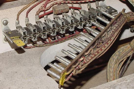
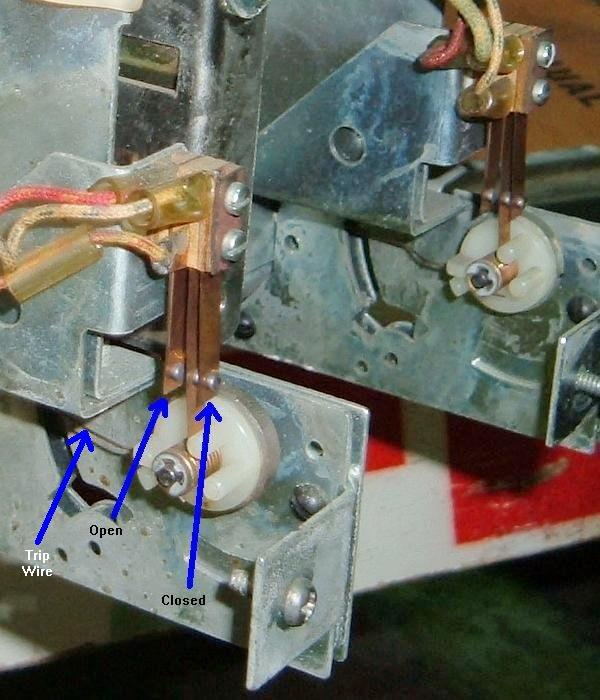
Williams coin door switches on a 1976 Grand Prix.
Note the make/break coin switches and how they are intended to look.
These Williams coin switches love to get mangled because they are light duty
and easily accessible by large sausage like fingers.
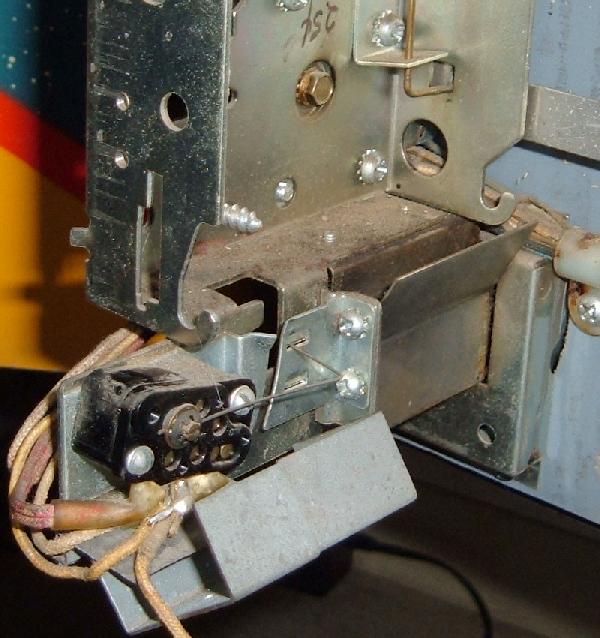
Bally coin door switch on a 1971 Four Million BC.
Here the coin switch protector is bent back, exposing the switch.
That's pretty typical, as someone wanted to add credits with their
fingers, so this is how the switch becomes "finger ready." (Or how the
switch gets damaged.)
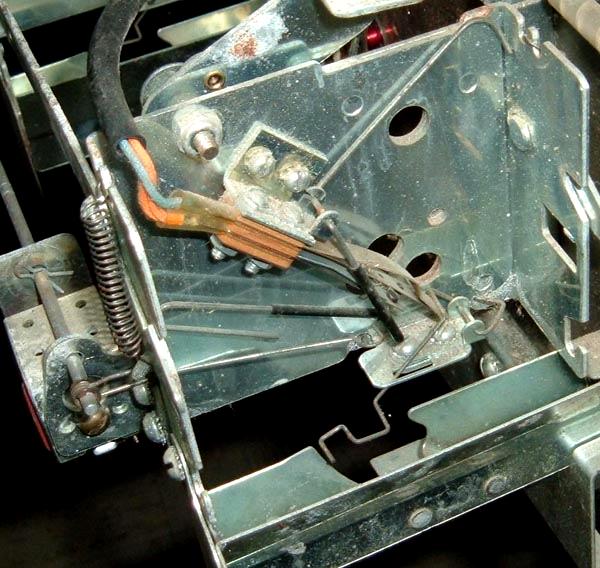
Gottlieb coin door switches on a 1971 "2001."
Gottlieb coin door switches are protected from abuse because they are not
easily accessible without removing the coin mechanism.
Because of the potential problems with coin switches,
I always recommend you make your game
"Free Play". This way you
don't have to deal with coin door switches. Check the coin door switches
so they are properly adjusted, set the game to Free Play, and play some
pinball!
I know some people want that romantic ability to "drop a coin" to start
a game. RESIST THIS TEMPTATION. I fix more games with coin door problems
and probably any other single problem. Jammed coins, bent coin switches,
strange coin door modifications can all cause a game to not work. It's
just not worth it. Put the game on free play and forget about dropping
coins to start a game. Trust me - your emotions will be much better
served playing pinball than putting a coin into a coin slot.
If coin door switches do get mangled, they usually get bent closed.
This will put the game into "max credit mode." Meaning the game will
keep adding credits until the credit unit maxes out. This often means
the game will jam the credit unit, locking the knocker coil on, and
often keeping the score motor running.
Before I fix any EM game, I always look at the coin door switches first.
It just takes a second to see if they have been molested.
2d. Before Turning the Game On: Stepper Units
The Biggest Problem in EM Games.
The most common failure point in EM games are the stepper units. Steppers
have at least one coil that "steps up" the mechanism, giving a different
bonus level or player number or ball number. Often these stepper
units bind or have other problems. If a stepper unit does not operate freely, the GAME WILL
NEVER WORK.
There are basically three kinds of stepper units:
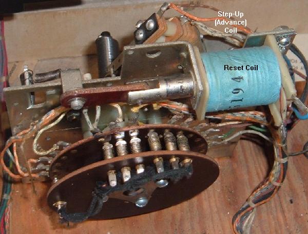
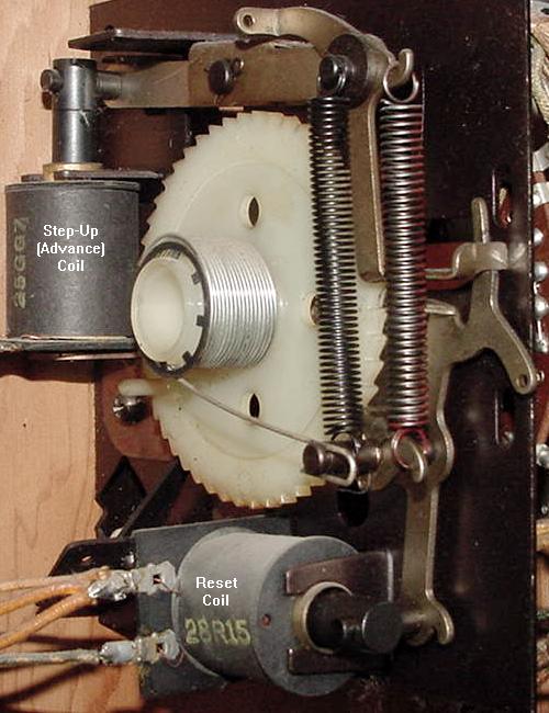
Step-Up/Reset units: AKA Total Reset steppers.
Have two coils- one coil for a step-up, and another coil that resets the
unit back to its home or reset position. The step up/reset units are often
used for the player unit, ball count unit, and coin unit. This is probably
the most common style of stepper unit.
Increment/Decrement units: AKA Single Step Reset steppers.
Have two coils- one coil for a step-up, and another coil that steps-down, one step at a time.
These are most often used for bonus counts. Note Williams sometimes combined a single step
reset unit adding a third relay coil to do a total reset
(bonus stepper units during the 1970s like on "Grand Prix.")
Continuous Rotation stepper units:
Only have one coil. For it to find its "home" position, it
must revolve all the way around (there is no reset coil). The continuous
stepper is often used for changing features of the game and for
the match unit. On woodrails often the 10,000 point stepper unit is a
continuous rotation stepper.
Stepper units are used for a variety of uses. If you have a 1950's
EM game, they are used for the lightbox scoring. There's a stepper
for each scoring range (hundreds, thousands, ten thousands, etc.).
Each stepper will have a step up coil, and a reset coil (to
reset the points to zero), which is a step up/reset stepper.
Usually the lowest scoring stepper
(like the zero to 10,000 point stepper) won't have a reset but
will just rotate around to the zero position (continuous stepper).
Stepper units are
also used extensively in score reel era games too.
Uses for steppers include counting bonus points, keeping track
of the current ball number, matching (at the end of a game), keeping
track of number of coins dropped, and keeping
track of the player number (for two and four player games).
A "working" stepper unit must step up correctly
and easily, and reset or step down to its "home" position easily
(assuming its not a continuous stepper). The "fingers" of the
stepper unit must make good contact with the bakelite plate
mounted rivets too. Often the grease used
to originally lubricate the stepper from the factory has turned
solid, and prevents the stepper unit from either stepping
up, or reseting. The grease on the coil activated levers
makes the levers "lazy" (not allowing the stepper to step up
or down correctly). Also the brass rivets and fingers that glide
over the rivets need to be cleaned. Years and years of
oxidation and crud prevents light and game
functions from working.
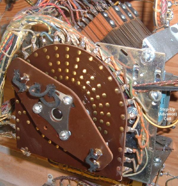
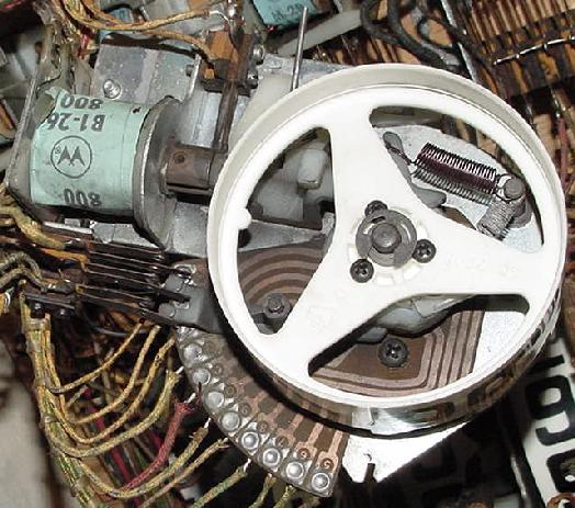
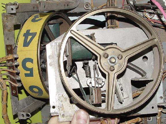
Bally Continuous Rotations stepper, with no step-down or reset coil. This
unit is known as a "00 to 90" unit, and is used for the match. Advances
each time the 10 point relay energizes to change the match number, and to
often change a set of playfield features (Bally "4 Million BC.") It also
has a mechanical "clapper bell" installed, thus reducing the need for
another assembly for 10 point sound.
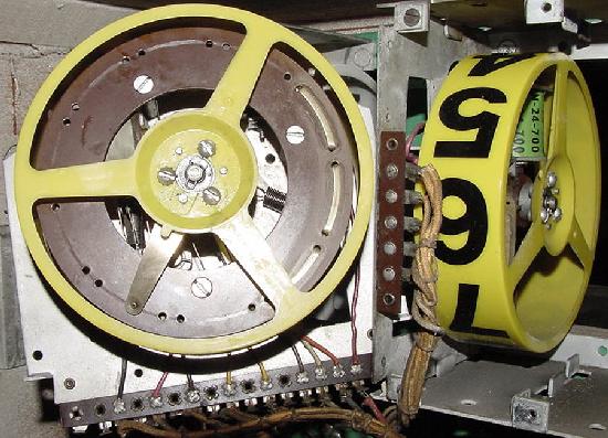
Back side of the Bally Continuous Rotation stepper.
Gottlieb Continuous Rotation unit. This is the Player unit, used on most
multi-player Gottlieb EMs from the 1960s forward. The switch stacks behind the unit
are more problematic than the "finger" contact points that rotate (Gtb Target Alpha.)
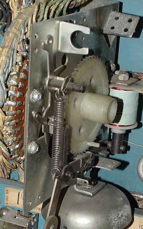
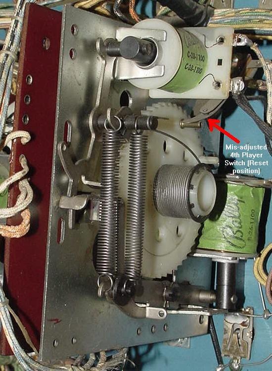
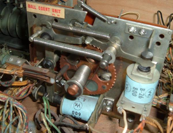
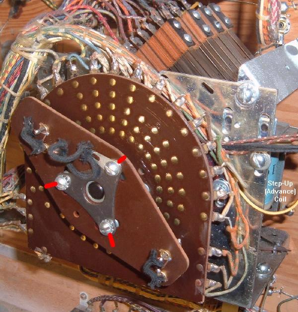
Bally Step-Up/Reset (aka Total Reset) Unit. There's a coil to step up the unit, and
another coil to reset the unit. Note the 4th player switch is MIS-ADJUSTED in this
picture. This is one of the most common problems seen on Bally Coin units.
(Picture shows the Coin unit in the "reset" position.) Bally "4 Million BC."
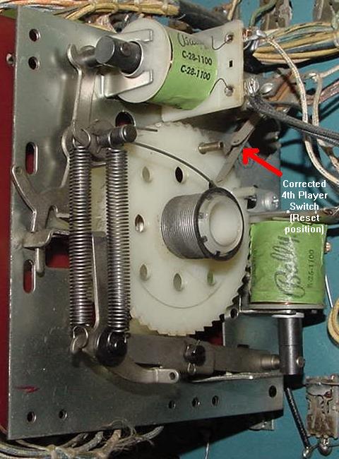
Bally Coin unit (4 Million BC.) Same Total Reset unit as the picture above,
but the 4th player switch is CORRECTED in this picture. This switch (red arrow)
should open when the 4th player is "coined up." (Picture shows the Coin
unit in the "reset" position.)
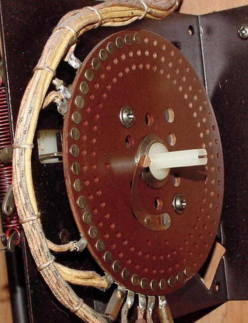
Bally Step-Up/Reset (aka Total Reset) Unit. This is the Coin unit,
bakelite side. (Again Bally "4 Million BC.")
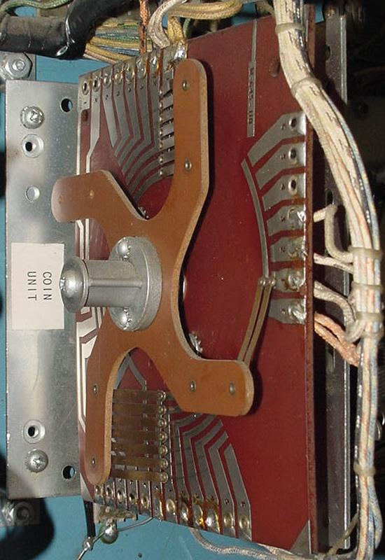
Gottlieb Coin Unit. This style unit used from 1975 to 1979 (when the reset bank
was abandoned on Gottlieb EM games). Located right in front of the chime box in the
lower cabinet, this unit tells the game how many players will be playing (coins
inserted) for the current game. This is a Total Reset stepper (Fast Draw/Royal Flush),
but interestingly Gottlieb also used a Step Up/Step Down style unit for the coin unit
instead in 1977 on many four player games (like Target Alpha.)
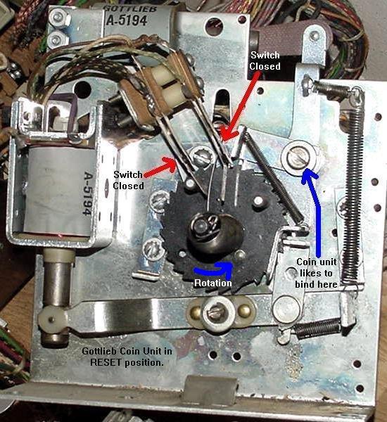
Gottlieb Coin Unit. This shows how the switches are positioned when the
game is reset and ready to play for ONE player.
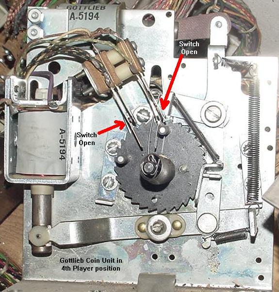
Gottlieb Coin Unit. This shows how the switches are positioned when the
game is ready to play for FOUR players.
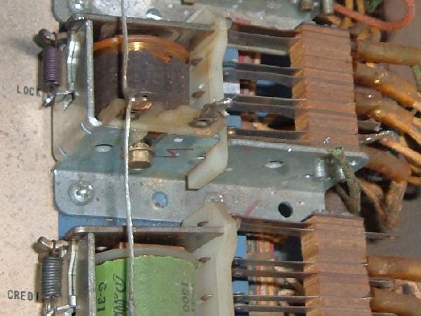
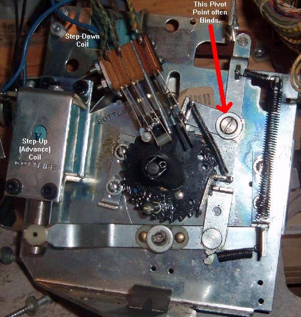
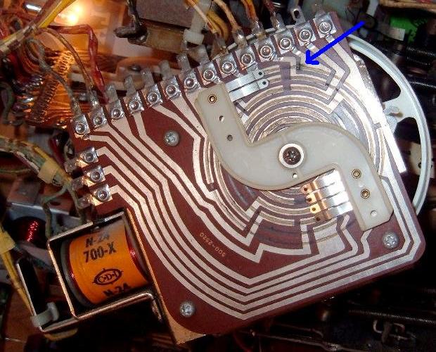
Gottlieb Credit (Replay) Unit in the backbox. This is a Step-Up/Step-Down
(Single Step Up Reset) style unit. The common binding point is shown here,
preventing the unit from stepping down (or up) properly (Gtb Target Alpha.)
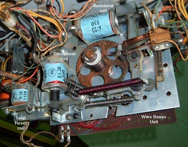
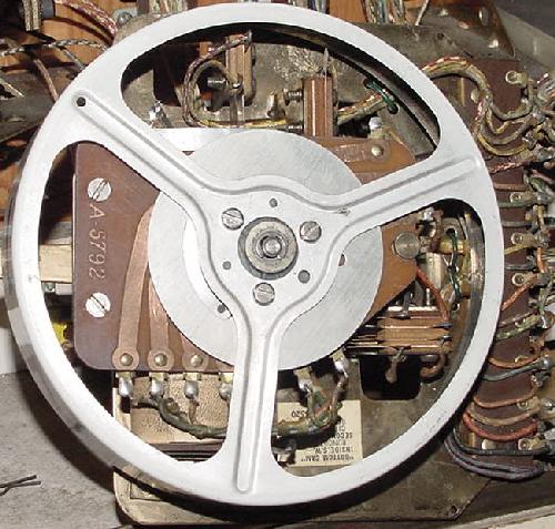
Williams Bonus unit. This is a Step-Up/Step-Down (Single Step Up Reset) unit
conbined with a total reset coil. Notice the small relay coin at the left side
of the picture. When pulled in with the decrement coil, this will do a total
reset of the unit. This speeds up a unit reset, instead of it slowly single
stepping down to the reset position.
Each and every stepper unit in any EM game needs to be examined, cleaned and
manually tested for proper operation. Common problems associated with
stepper units are:
Game cannot be started.
Score motor continues to run when a new game is attempted.
Game credits not added or taken off, or too many are taken off.
Current ball number in play never changes (always stuck on ball 1 for example).
Can't change number of players on multi-player games (only 1 player allowed
or won't reset back to 1 player).
Bonus points don't score, or count up or down correctly.
Match number always the same.
Score won't reset to zero (1950's games with lightbox scoring).
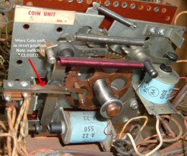
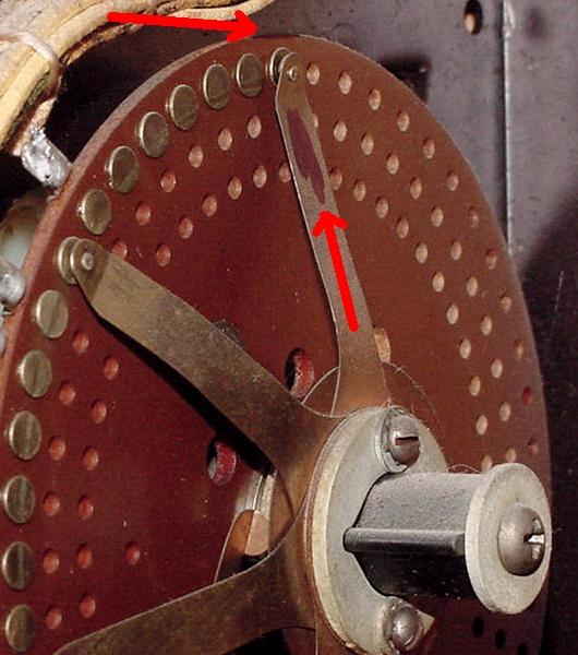
Williams Coin unit shown in reset position. Note switch is closed (1974 Fantastic).
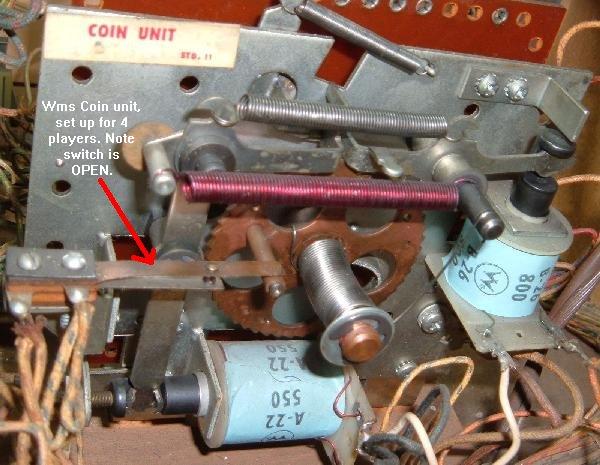
Williams Coin unit shown in 4 players position. Note switch is now open (1974 Fantastic).
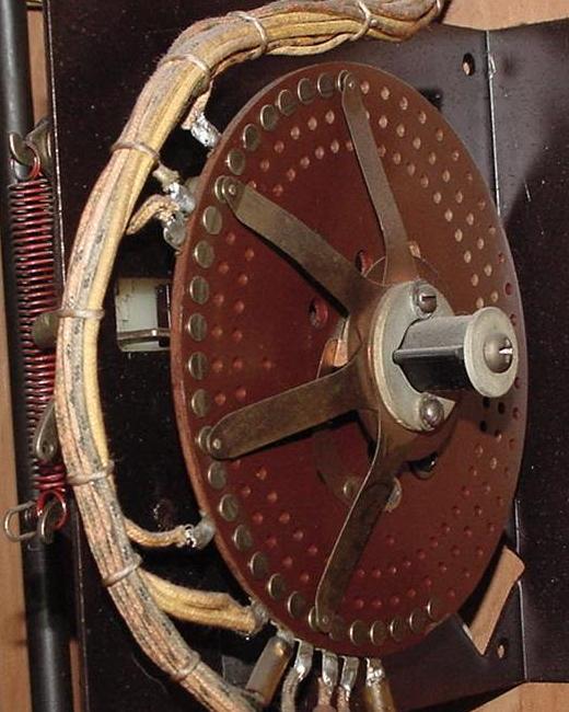
Williams Ball Count unit, in reset position with switches open (1974 Fantastic).
Note the metal wiper "fingers" on each stepper unit. These wiper fingers
determine the path the electricity takes for each step of
a stepper unit. The wiper fingers move across a series of brass
rivets or across a printed circuit board. These rivets or circuit board
must be clean for good contact.
Cleaning a Stepper Unit.
To clean a stepper unit, you will need a few tools. A phillips and flat head
screwdriver, a small adjustable wrench, some Isopropyl Alcohol (or for really seized
stepper units, Brake Part Cleaner), some 400 or 600 grit sandpaper (or
a 3M green pad), paper towels, and some Teflon Gel Lube. Do NOT use steel wool for
anything in an EM game, especially a stepper unit! (Those little steel wool "hairs" like
to hang around and later catch on fire.) Here's the procedure:
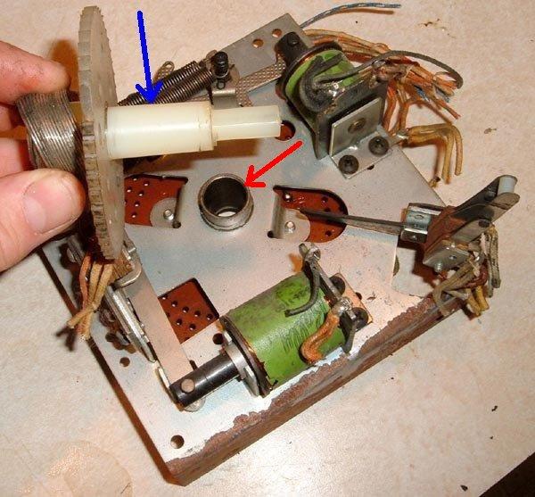
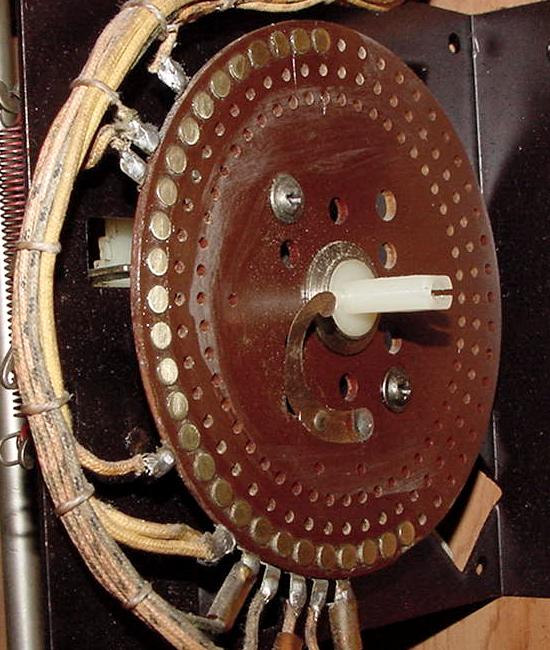
This is a Reset Stepper on a 1959 Bally All-Star Bowler that we will be using for
this cleaning example. This is a typical Total Reset stepper unit, as found on Bally,
Williams, United, Chicago Coin, and other manufacturers. Gottlieb Steppers usually
look a bit different, but functionality it's the same, as is the cleaning procedure.
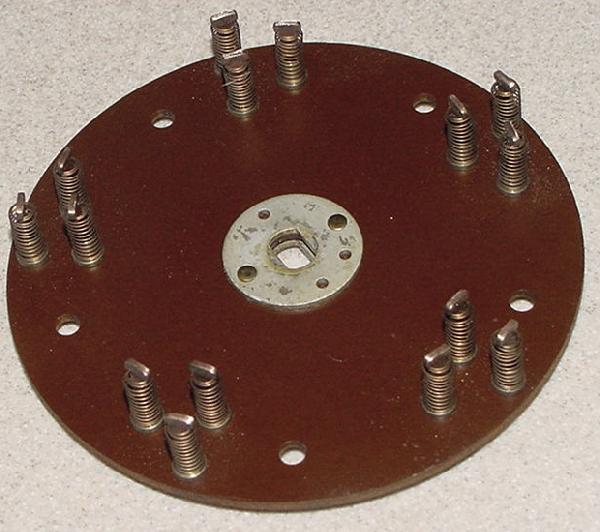
This is the rivet side of the stepper unit we'll be working with.
Turn the power off to the game.
Set the unit to the reset position. This is only necessary
on steppers that have two coils (a step-up coil, and a step-down
or reset coil - continuous rotation steppers with just one advancing coil
don't need to be marked.) Use a "Sharpie" pen and mark the zero
position on one of the wiper fingers and on the edge of the bakelite board
right by the mating brass rivet the finger touches
(for future reference, otherwise you could
assemble the unit 180 degrees in reverse!) So what if the
stepper is so gummed up you can't get it into the reset
position? Well mark a finger and it's rivet position
as the stepper currently sits.
With the Stepper in the reset position, mark a finger and it's related rivet
location using a Sharpie pen. Mark the bakelite board on the EDGE, not on the
rivet. You will see why in a moment.
Check the fingers/rivets for proper alignment. Best to do
this now, before taking anything apart. With the stepper
in the reset position, make sure the fingers rests squarely
and centered on the rivets. If they do not, the stationary
bakelite plate's attachments screws may be loose, and the
bakelite plate shifted. (This can cause some really weird
game behavior!) Best to check for this now. If the
fingers are *between* two rivets, you need to figure out
which way to rotate the bakelite plate to fix this problem,
and then tighten the bakelite disc screws.
Carefully remove the fingers from the stepper unit. Note on
some units (like the Gottlieb Player Unit) this step may not
be required, because the rivets are easily accessible without
removing the finger disc. This assumes that the unit is not
excessively binding and can be manually advanced.
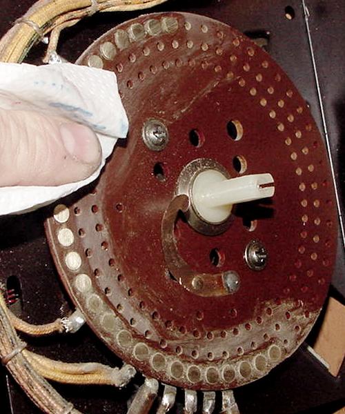
Gottlieb Player Unit. On this Continuous Rotation style unit the finger disc
does not need to be removed to clean and polish the rivets. Of course this
assumes the unit does advance without too much difficulty (Target Alpha).
The player unit is a nasty beast to disassemble, so not having to take
this unit apart will save your sanity. If a Gottlieb finger disc does need
to be removed, note the red marks showing alignment of the finger disc
relative to the mounting screws.
For most units, the finger disc will need to be removed. On a Bally
stepper, this means removing a phillips head screw, and then pulling
the finger disc off the stepper shaft. You will have to hold the
nylon cog on the other side of the stepper unit to prevent it from
turning while removing the phillips screw. On a Williams stepper, there is a 7/16" nut which holds
the finger disc in place. To remove this nut, on the opposite
side of the stepper, put a small screw driver into one of the large
holes in the stepper cog to prevent it from turning. On a Gottlieb
stepper, often just removing two or three slot head screws will
remove the finger disc.
Here's the Bally stepper with the finger disc removed.
Now try spinning the cog on the cog side of the stepper.
If the unit is in the reset position, it should spin clockwise
(as looking at the cog side). On some steppers you may have to
hold a coil in the energized position to get the cog to spin.
Does the cog spin freely? If so,
that's good news, as you can skip the following steps 5a to 5g.
(On most games you will be able to skip steps 5a to 5g - 1950s
United games will usually require steps 5a to 5g.)
If the cog does not spin freely, you will have do some more work:
The cog side of the Stepper Unit.
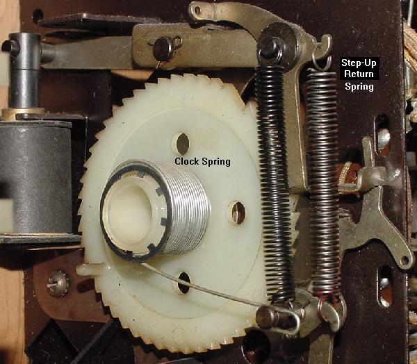
Step 5a. Remove the SPRING that winds the unit. This is sometimes
called the "clock spring". This is
only necessary on steppers that have two coils (single coil continuous
stepper won't have a clock spring). When
releasing the spring, COUNT the spring windings as the spring
is unwound. Write the number of spring turns on the stepper unit
itself with a Sharpie pen (usually this is three or four).
Step 5b. Now the shaft/cog will pull out from the cog side. Sometimes a switch stack will
prevent this - just remove *one* screw (the one closest to the switch
contacts) from the switch stack, and rotate the switch stack out of
the way. (Often the other stack screw may need to be loosened.)
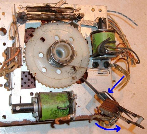
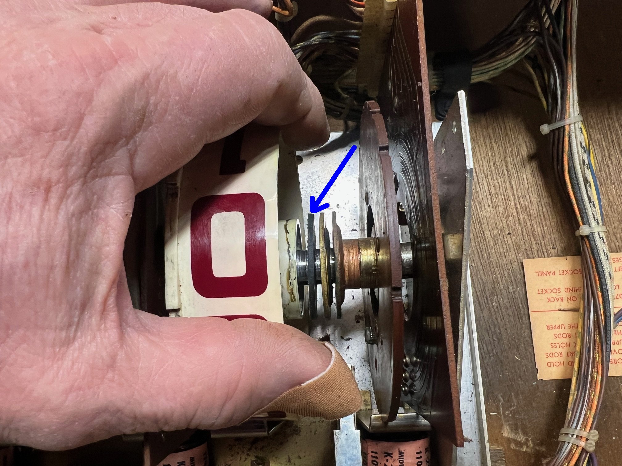
A Bally total reset stepper with one switch stack screw removed (blue arrow),
and the entire switch stack rotated out of the way. This allows the stepper
cog (big white gear) to be removed without obstruction.
Step 5c. Clean everything with Alcohol, and
if the cog shaft is metal and rough, sand the shaft smooth with 400 or 600 grit sandpaper or a 3M green pad.
(Don't sand on nylon Bally cog shafts.) Remember never use Steel Wool!
You may have to remove a mechanism spring or two to get the shaft out.
Make notes and drawings or take digital pictures if you are afraid
you can't remember where the springs and levers go. Alternatively
compare this stepper unit to another in the game if things get confusing.
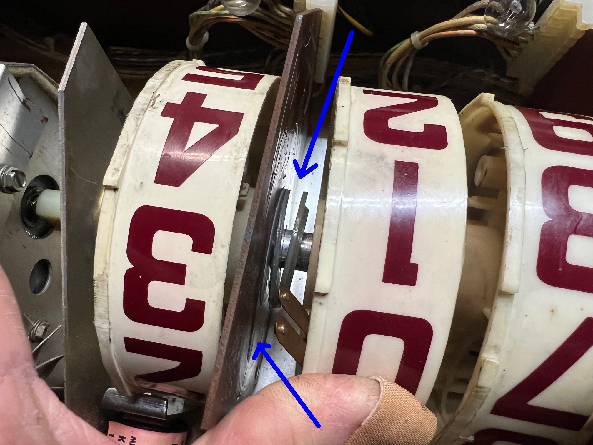
A Bally total reset stepper with the cog removed. The blue arrow shows the
area of the cog shaft that needs to be cleaned. The red arrow shows the shaft
hole that will need to be cleaned.
Step 5d. Using Alcohol and a Q-Tip, clean the Stepper Unit's hole that the shaft/cog
goes through.
Step 5e. After the shaft/cog and hole is clean, put a thin layer of Teflon Lube Gel
on the shaft. Install the shaft into the Stepper Unit. If a switch was swung
out of the way, put it back and re-install its attachment screw.
Step 5f. Now try spinning the cog on the other cog side of the stepper.
It should spin clockwise (as looking at the cog side) and freely.
If not you did something wrong!
Step 5g. Wind the clock spring back to the number of turns you documented
when it was removed. If any other springs were removed, re-attach those too.
Clean the bakelite disc's rivets. First use a rag and some
alcohol to remove all grease and other crud. Then use 400 or 600 grit sandpaper
to brighten the rivets. Some people use 3M Scotchbrite pads, which also works well
(I use the sandpaper because I already have that, and it's cheaper).
The idea is to make those rivets shine! (Do NOT use steel wool!)
After the rivets are sanded clean and smooth and shiny, clean them
again with a rag and alcohol.
Cleaning the rivets with Alcohol after they have been sanded.
Sand the finger contact pads clean with 400 or 600 grit sandpaper.
Also some fingers have a pointed contact point around the circumference of
the attachment shaft (very common on Bally steppers). If this is
the case, clean this area with sandpaper too.
On Gottlieb and some Williams steppers, the fingers are "snow shoe" style
and mounted in a bakelite disc. Make sure the fingers move freely inside
their metal conduit. I often clean this entire bakelite disc in an Alcohol
bath to ensure the snow-shoe fingers move freely in the bakelite disc.
Cleaning the finger pads with sandpaper. In a Bally stepper, often the
center circumference is a contact point too and needs to be sanded.
The bakelite disc and "snow shoe" style fingers. This style of stepper was used
on Gottlieb and Williams games, and is a more expensive stepper unit (Williams
later abandoned this stepper style in favor of the cheaper "fingers" style).
Make sure the snow shoes travel freely inside their metal conduit. Use an Alcohol
or Mean Green bath to soak to unit if the fingers do not move freely. Sometimes
the snow shoes get bent and prohibiting their movement. Gently bend straight, but
don't try and remove the snow shows from the conduit unless absolutely needed.
Sand clean the face of the snow shoes for good electrical contact.
Apply a thin film of Teflon Gel Lube to the bakelit disc rivets.
The Gel Lube is important, as it does three things. First it allows
the rotating fingers to glide easily over the stationary rivets.
Without the Gel Lube, the stepper has to work harder to move.
The Gel Lube also prevents the fingers from wearing out the rivets.
And lastly, the Gel Lube provides a film to keep the rivets shiny
and very conductive, stopping corrosion.
The rivets with a thin layer of Teflon Gel Lube on the rivets.
Put the fingers back onto the stepper's cog shaft. Hold
the cog shaft in place while pushing the finger disc onto the shaft,
to prevent the cog shaft from moving out of place and "unwinding".
Put the screw(s) or nut back to keep the fingers in place. Do *not* over-tighten.
Make sure the wiper finger Sharpie lines match up with the stepper unit when reset.
Test the Stepper unit. Manually activate the advance coil to
see how the stepper moves. Reset the unit (assuming this is not a
continuous stepper). It should come back to
the reset position cleanly (or on a Step-down unit, it should back down
one step cleanly). The idea is to have just enough tension
on the clock spring to bring the stepper back to reset. Too much
clock spring tension, and you're making the advance coil work too
hard to step up the unit.
Check the Step-Up Return Spring. Even if the clock spring is
not over-tensioned on Reset and Step-Down units, sometimes the Step-up coil will
not spring back crisp and firm. (If the clock spring is over-tensioned,
the step-up return spring may not work at all!)
The Step-Up Return spring may need some slight modification.
With time and the elements, springs can lose their elasticity. Sometimes
you will need to cut a few turns, or even 1/4" to 3/8" off the Step-Up Return
spring to increase the return tension. Then bend out the top-most spring
loop to create a new spring connection point.
This modification is fairly common, and it does apply to Continuous steppper units too.
Check/clean the Step-up coil plunger and
coil sleeve on the stepper unit with alcohol (DO NOT lube!) Sometimes
the coil sleeve was mistakenly lubricated, which has now gummed up.
Or the plunger has a "mushroomed" end, causing resistance inside
the coil sleeve (the mushroom can be filed off).
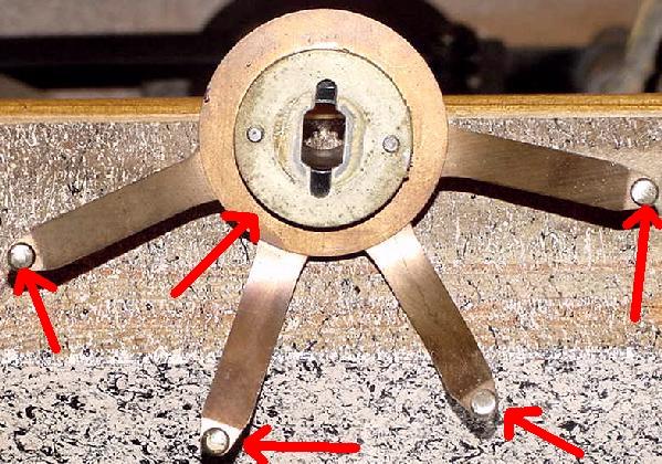
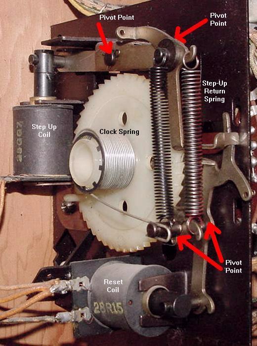
The red arrows show pivot points on the activator arms that can become
lazy and make a stepper unit not step-up or step-down properly.
Check the step-up and reset/step-down activator arms. All the
pivot points on these arms should move freely. If they are gummed
up, they will require disassembly and cleaning with alcohol. Any
metal-to-metal pivot points should be lightly lubricated with
Teflon Gel Lube. If any of these pivot points are sticky, the steppers
may not step-up or step-down reliably (or at all).
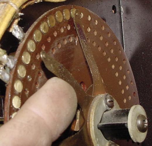
Checking the finger tension on the rivets. There should be adequate tension
for reliable contact. But too much tension will make the stepper unit work
too hard to step-up or step-down.
Check the finger tension on the rivets. Gently pull a finger
back from the rivet, and let it snap back to position. It should snap
back firmly, but without too much tension. Fingers that are too tight
against their rivets will make advancing or resetting a stepper unit too
difficult. If a finger has too little pressure, there won't be good
electrical contact between the finger and the rivet. If a finger needs
additional contact pressure, remove the finger plate and gently bend
the desired finger. If it has too much tension, just bend the finger
back slightly (without removing anything). On Gottlieb units, make
sure the fingers move freely and don't bind in their metal casing (do not lubricate
the casing).
Last, check the fingers and rivet alignment, just as you did
before you took the stepper apart. The fingers should align on the
center of the rivets. The stationary bakelite plate may need some
slight tweaking to align the fingers/rivets.
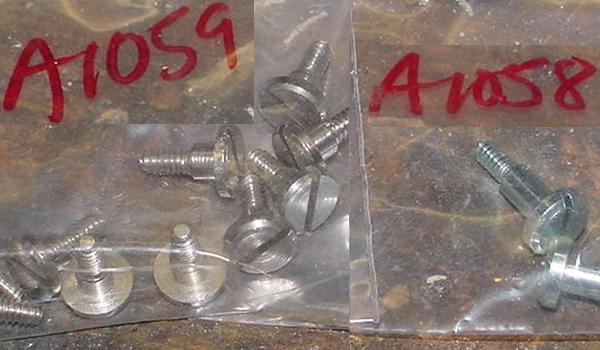
Gottlieb shoulder bolts. Available from Pinball Resource, keep a few
of these around. (Part# a1059 is the most common one.)
Gottlieb Stepper Unit Shoulder Bolts (a Warning.)
On many Gottlieb stepper units (the backbox Credit unit
and the bottom panel Coin unit), these units like to bind
at the "shoulder bolt" pivot point for the step up/down arms.
This is a pivot point that was factory
lubed with white grease. Over time, the white grease solidifies,
and the unit will not step up and/or won't reset.
The solution to this is to remove the shoulder bolt and to clean
off the old solidified white grease with alcohol. Then re-lube with Teflon Gel Lube
and reassemble.
WARNING. This shoulder bolt has a nut on the back side.
If this nut is not removed, and a big screwdriver is put on
the shoulder bolt to turn it, the shoulder bolt will shear. This renders the shoulder
bolt useless. If this happens nothing short of ordering a new
shoulder bolt from Pinball Resource (part# a1059) will fix the problem.
So the moral of this story is to first remove the nut from the
shoulder bolt before removing/adjusting this bolt. (And even then during
nut removal sometimes the shoulder bolt still shears.)
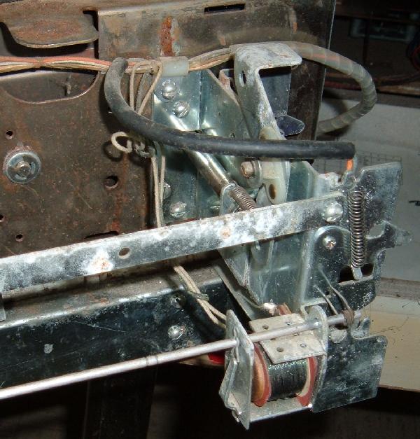
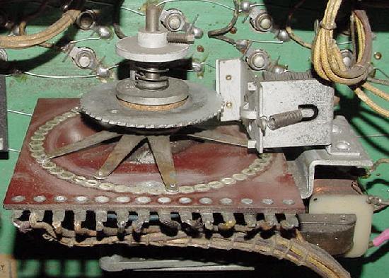
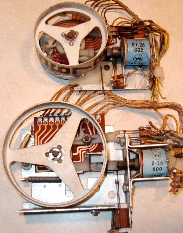
A 1960s Chicago Coin continuous rotation motorized stepper unit.
This unit uses a motor to move the stepper, and a lock relay (right) is used
as a "brake" to quickly stop the stepper at a precise location.
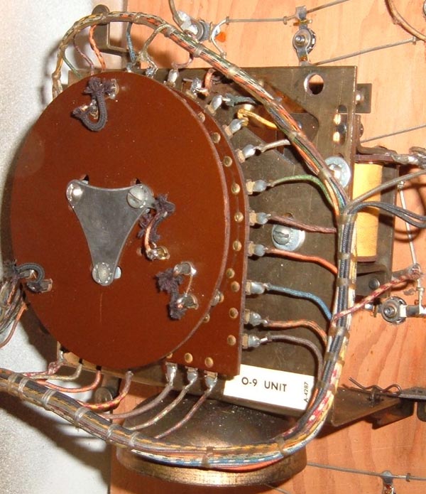
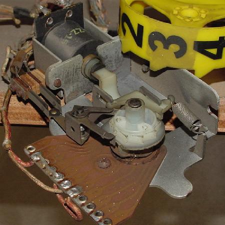
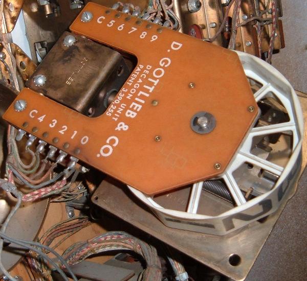
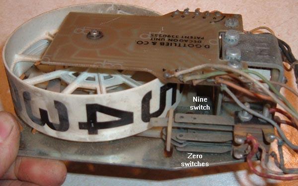
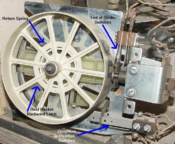
Gottlieb 0-9 continuous rotation stepper unit. As used on a 1965 Kings and Queens.
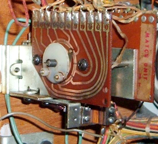
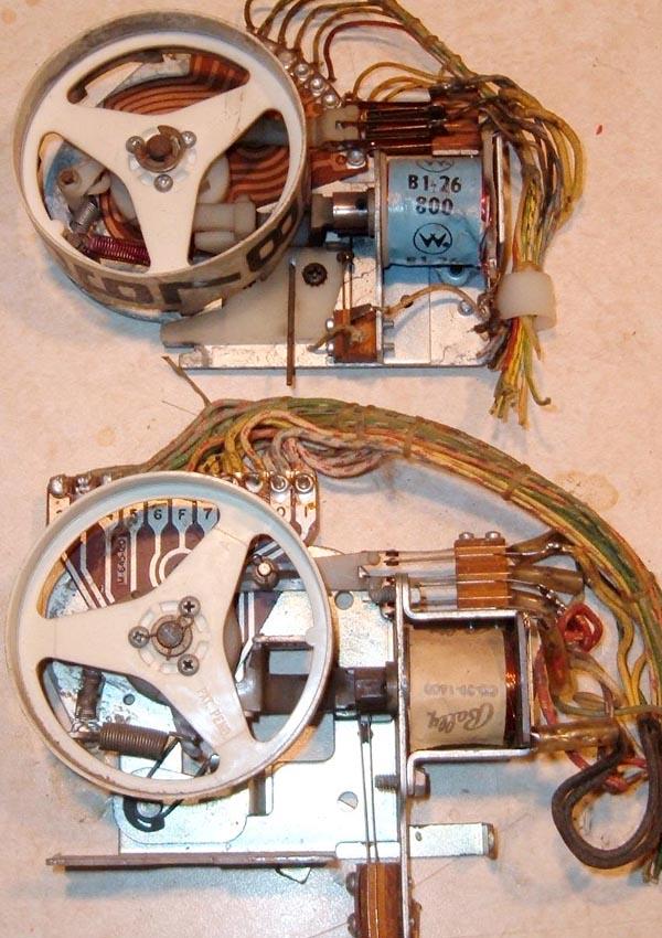
Williams continuous rotation match stepper unit. This is Williams equivalent
to Gottlieb's AS relay. A mini stepper, with small, impossible to find, and
hard to service parts (1975 Williams Space Mission.)
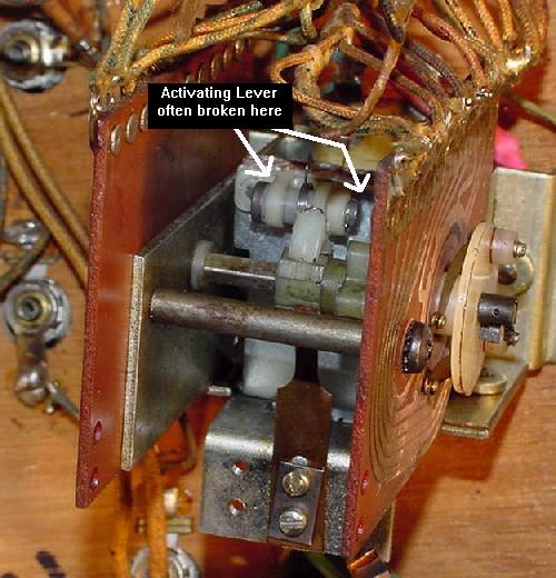
Another look at the small Williams match stepper unit (Space Mission 1975).
A relay coil is used to pull in the metal activator plate, which has a small
nylon lever attached. This lever then moves a small nylon gear on the
rotating shaft to advance the match unit's contact wipers. Often the
nylon lever breaks where it connects to the metal activator plate. This
was really a cheap design for a stepper that gets activated so much.
Armature plate assembly #WLL-A7989.
Fixing a damaged stepper unit
wiper arm.
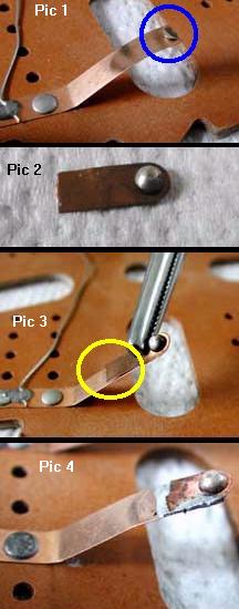
Fixing a Broken or Worn Wiper Blade.
This information and picture is thanks to Michael Sands.
Sometimes the metal fingers on stepper units break, or the contact on the finger
will wear out. This can be repaired, as new contacts can be purchased from Pinball
Resource. But if the wiper blade is broken, it cannot be replaced easily,
but it can be repaired.
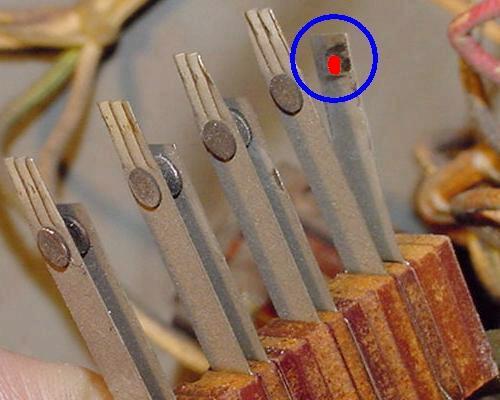
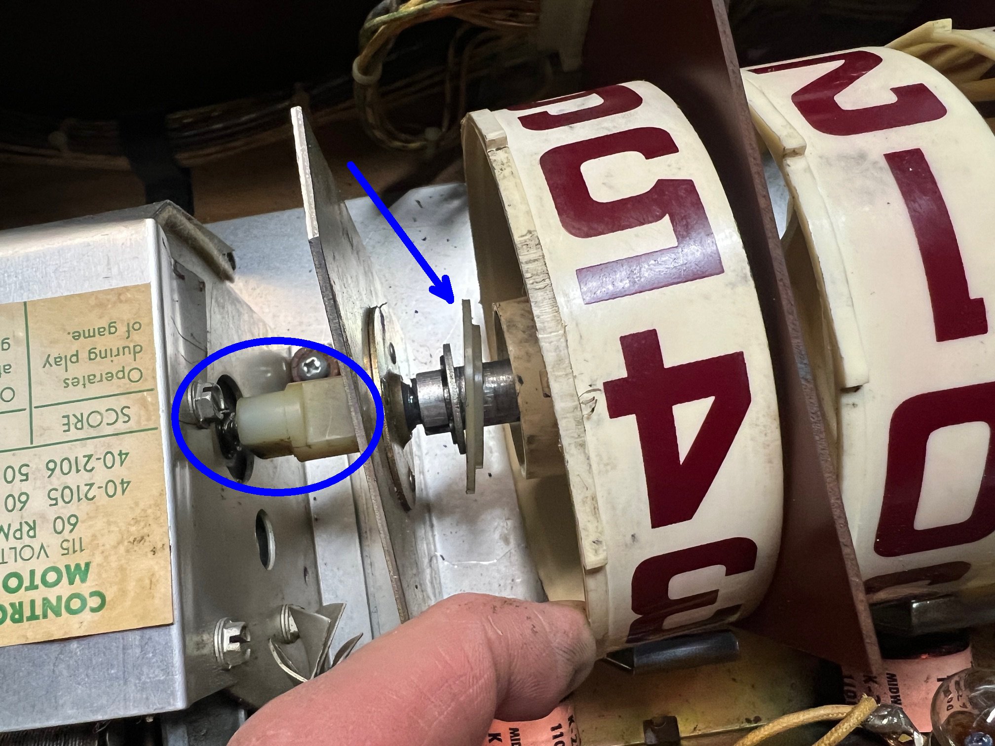
First shine up the metal on the old wiper blade arm. Cut off the contact if it
is still there, but leaving as much of the arm as possible. Note the arm bends and acts
like a leaf spring, pressing the contact against the rivets. See pic 1 to the left,
showing a damaged wiper arm contact that needs to be repaired in the blue circle.
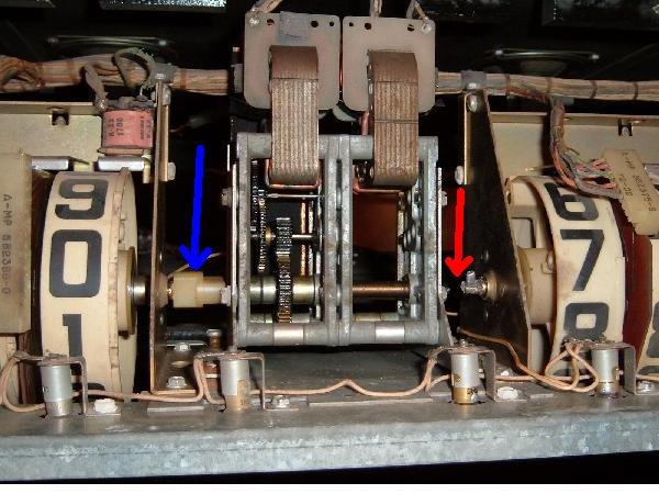
Next find an old "parts" stepper unit, and
cut off the contacts from this parts stepper. Keep the length short because
the double thickness of metal will not have the same spring. Shine up both the
front and back sides of the cut wiper arm. See pic 2 to the left.
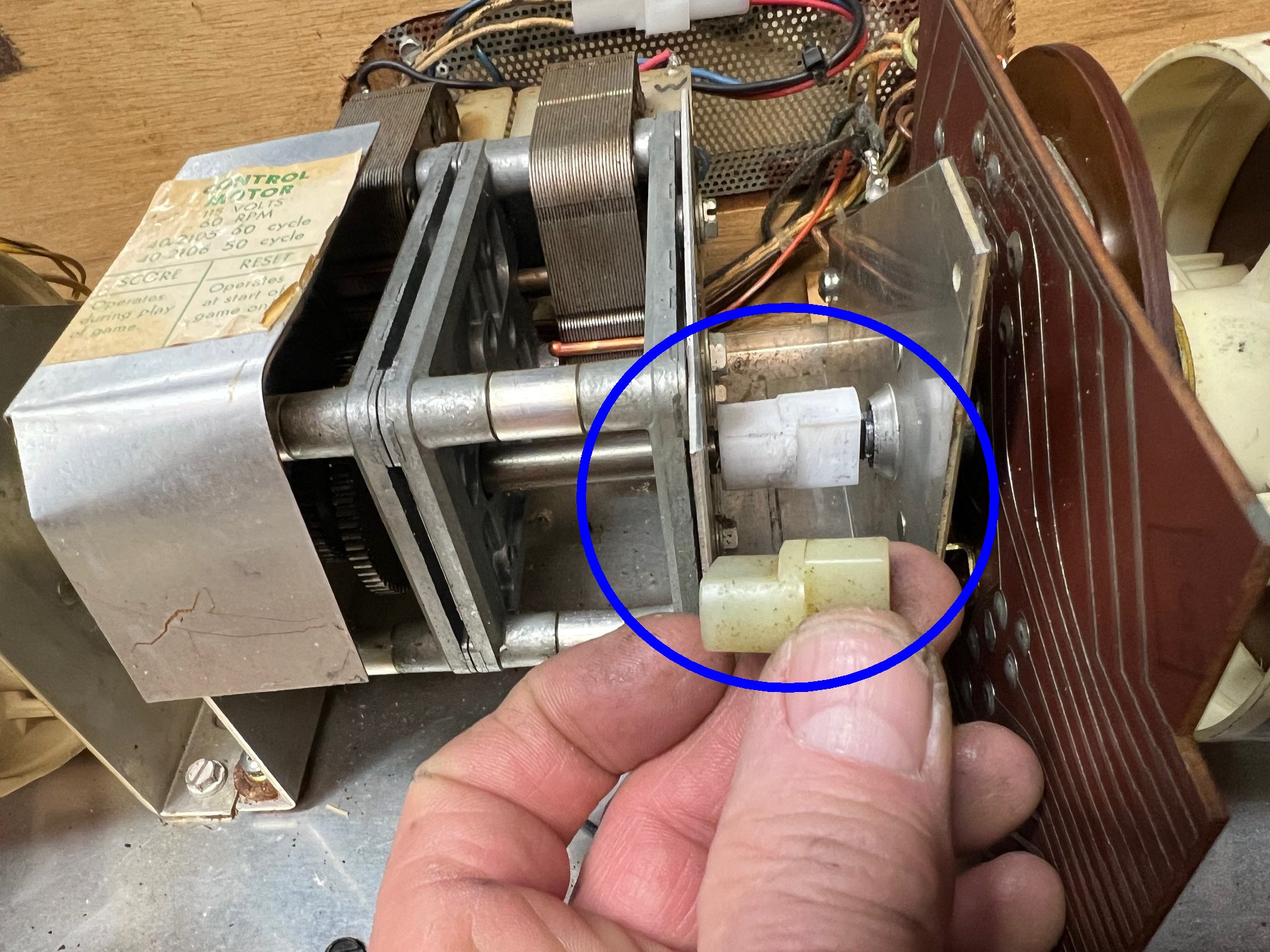
Put some soldering flux on the new and original wiper arms (this will
help with the soldering).
Clamp the new wiper arm onto the shiny portion of the original arm,
in the same position as the original wiper. Carefully note the length!
The wiper arm can not be longer or shorter than originally designed.
See pic 3 to the left, in the yellow circle.
Solder the new wiper arm in place on the original wiper arm.
(see pic 4 to the left).
Regular rosin core solder works fine. Alternatively, a silver solder with
can be used for added strength.
Stepper Alignment Problems.
Something I always check with stepper units after they are rebuilt
is the alignment of the "wiper fingers" with the "rivets" on the bakelite
plate. With time, or because someone else messed with it, the metal contact
point on the wiper fingers may not center on the heads of the brass
rivets. This can even be so much of a problem that the wiper fingers line
up "one rivet off" (though this is rare, but I have seen it on a
Williams game, where the ball in play unit was at "negative one" instead
of "zero" when reset, and the game just would not play right!)
Other symptoms of this problem are games that end at the wrong time.
For example one user reported a problem with a Gottlieb Sky Jump (1975).
After the fifth (last) ball had been played, the game was not over.
A sixth ball was served, but as soon as the ball hit the trough
switch the game finally ended to "Game Over" and the match feature lit.
To check the alignment, after rebuilding the stepper
unit, reset the unit to the "zero" position. Look at the wiper in
relationship to the brass rivet it mates. Now advance the
stepper a few times. Again, notice the wiper/rivet relationship.
The wiper finger should center on the rivets, and not be
off to either side. If it is off to the side, the bakelite plate needs to be
adjusted slightly.
Most stepper units have two, three or four machine screws that
attach the brown bakelite disk to the frame of the stepper. If
these screws are loosened, the whole bakelite disk can turn
a few degrees in either direction. Loosen the screws just a bit,
so there is still resistance on the bakelite plate. Now gently
rotate the bakelite plate to align the wiper fingers to the
center part of the rivets. After they are aligned, move the
stepper a few times to verify all positions have the wiper fingers
centered on the rivets. Then tighten the screws.
Burnt Stepper Wiring.
A problem that is hard to see, but that can cause torn
hair from thou's head, is burnt stepper wiring. Example:
1954 Gottlieb Daisy May I was working on. This game
refused to reset properly, and the ball release coil would
stay energized. I kept coming back to the
points stepper unit. I had cleaned and repaired the
stepper so it worked perfectly. But I still had this
nagging reset problem (the points unit, after reseting,
would not increment from the "-1" position to the "0" position,
thus allowing a 10,000 point playfield hit to de-energize
the ball release coil).
I finally saw the problem after I removed the stationary
bakelit plate from the points stepper unit. The wires on the *back*
of the stepper plate that connect the stationary rivet points to the solder
lugs around the edge of the bakelite plate had burned,
causing an open circuit (see picture below). This happened because
the ball release coil stays energized for a period of time. These
fairly small gauge wires are the weakest link in the chain, hence they
have a habit of burning before anything else would. By attaching
new (thicker) wires, the problem was fixed.
The back of the stationary bakelite plate on the Points stepper unit
(1954 Gottlieb Daisy May). The two blue arrows show where two rivet points
connect to two solder lugs. These connection wires were burnt and open.
Large Resistor on the Gottlieb Stepper Unit (preventing rivet burn).
On many Gottlieb EMs, the 0-9 stepper unit runs a playfield mounted
alternating relay. This relay alters some of the game features like
maybe pop bumpers moving between 1 and 10 points every time a 1 point
switch is scored. To turn the alternating relay off and on,
there are a set of rivets arranged so that every other step of the 0-9 stepper unit,
the alternating relay toggles On or Off. A pair of bridged wipers goes
across these rivets to complete the circuit to the alternating relay and
provide the alternating function, as the 0-9 unit steps around.
The problem with this arrangement is that as the wipers move off a
set of stepper unit rivets, an EMF spike is generated as the alternating relay coil is de-energized.
This causes an arc or spark at the edge of the rivets and wipers.
(This is similar to the back EMF spike that is suppressed on solidstate games
with a 1n4004 diode across DC coils.) The arc causes the
wipers, rivets, and bakelite base to burn and wear out more quickly
than normal. (This can really be seen on Williams EM games that have a
match unit which alternates a feature relay.)
To prevent the 0-9 stepper unit rivets from burning,
Gottlieb often used a 470 ohm 2 watt resistor across the rivet portion of the circuit.
This increases the relay coil's resistance from about 25 ohms to 470+25 ohms.
In turn this suppresses the EMF arc so the wiper and rivets don't burn up.
With this resistor bridging the rivets, the alternating
relay coil is never really "off" during the game (it just has reduced power,
which is not enough to pull-in the relay armature.)
Because of this no EMF spark is seen, and the stepper unit rivets
don't burn up. Note that sometimes you can hear a 60-cycle buzz coming from the
alternating relay when it is "off", because the relay is really
not "off", but is just powered through the 470 ohm resistor
(remember an increase in coil resistance makes the coil less powerful.)
Gottlieb's AS Relay (the Miniature Stepper).
Starting around 1966, Gottlieb stopped using a full sized 0-9 match
stepper unit and converted to a much smaller (and cheaper) AS relay stepper.
This is a miniaturized stepper that is much more delicate, and
made with many nylon parts. The biggest problem with this relay stepper
isn't the mechanism itself so much, as it is the people that work on it.
Because the unit is small and delicate, often it gets mis-handled, mis-adjusted, and
abused by over-zealous EM repair people.
Also in a lot of replay games,
the AS relay stepper may be missing from the backbox. This happens because
the AS relay is easily removed with two screws and two "Jones" plugs. This
was done to the match unit so it could be easily removed for territories that did not
allow players to win free games. So if you come across a Gottlieb EM with
two empty female Jones plugs in the backbox, the game is probably missing
the AS relay used for score matching. But the AS relay was also used for
some bigger tasks in 1970s games. For example in the 1976 Gottlieb Royal Flush
and Card Whiz, this relay was paramount to counting the drop target bonus.
If the AS relay was not advancing in these games, the entire game would
not work (score motor would continue to run while the game unsuccessfully
tries to advance the under-playfield mounted AS relay).
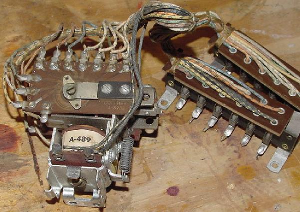
An AS Relay Stepper, as used in many game for the match unit. Notice
the two Jones plugs which aid in easy removal and service of the unit.
There are a couple of keys to servicing an AS stepper. First is this: do as little as possible
to make this stepper work. Personally I rarely take an AS relay apart. For one it's
difficult to work on because it's so small. But mostly I don't take it apart because
it is hard to get back together without over-bending something. I have personally
found it's just better to do this:
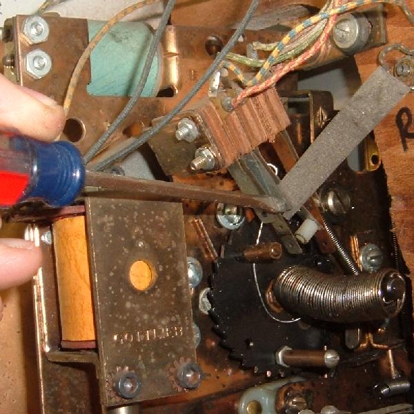
Sand the non-moving copper contact plate with 600 grit sandpaper. Some AS Relays
are double sided, so sand both outside non-moving contact plates. Don't remove anything
to do this. The enemy of good is better, in this case. Yea I know, you can't
get under the tension arm to clean. But so be it.
Lightly lube the non-moving copper contact plate(s) with Teflon Gel-Lube.
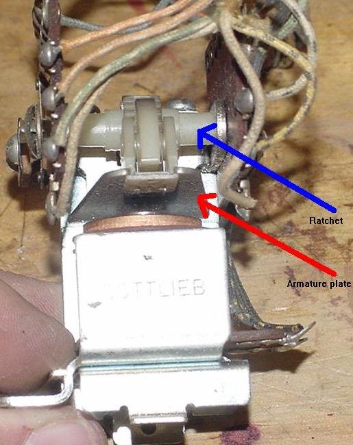
Test the AS relay. Using a thumb, press the armature plate down and quickly
release. The unit should move one step. If it does not,
check the switch(es) on the top of the AS Relay. Not all AS Relays have switches,
but many do. If the switches have too much blade tension on the ratchet, this can
cause the AS relay to bind and not advance. Very small adjustments to these switch(es)
can make a huge difference in how well the AS relay advances.
Test the AS relay again. If the movement of the moving arm is still sluggish,
remove the AS relay return spring and cut off TWO "loops" off the spring (and then bend
the last "loop" of the freshly cut spring up 90 degrees.)
Test the AS relay again. If the movement of the moving arm is still sluggish,
gently bend the tension arm just a little bit away from the non-moving plate.
This will reduce the tension on the moving arm, usually allowing it to move easier.
Test the AS relay again. If the movement of the moving arm is still sluggish,
you will need to replace the AS relay armature plate and AS relay ratchet. These
have nylon parts that warp with heat and time. If this has happened, no amount of
AS relay adjustment will make the relay work correctly. Note when replacing the ratchet,
the gear IS DIRECTIONAL. That is, make sure you install the new ratchet with the "teeth"
facing the same way as the original ratchet teeth were installed. It is easy to install
the ratchet "backwards", making the AS relay non-functional.
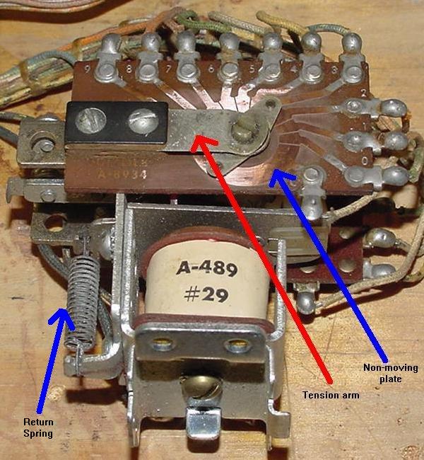
AS Relay showing one non-moving contact plate, the tension arm, and the return spring.
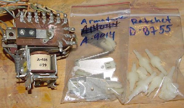
AS Relay armature plate and ratchet. These nylon parts take a beating, and
often need to be replaced.
AS Relay armature plate and ratchet, along with part numbers. Keep some on hand.
2e. Before Turning the Game On: Video of Various Stepper Units used in EM games
Movie of Various Stepper Units used in EM Pinball machines.
Below is a 5 minute movie I made of common EM pinball game electrical
parts and assemblies. This is a 640x480 movie file.
2f. Before Turning the Game On: Adjusting & Cleaning (Filing) Switch Contacts
The single biggest asset you have when fixing an EM game is your eyes!
Most problems can be *seen* on an EM game, if you take the time to
look. Before I turn any EM game on for the first time, and after
checking all the stepper units are working freely, I visually
inspect every switch. I look at all the relay switches, score motor
switches, and playfield switches. It does not take that long - I can
visually inspect all switches in a game in about 5 or 10 minutes.
You would be amazed at the problems that can be *seen* - broken
switch blades, obviously mis-adjusted switches, wires that have
broken solder joints from switch contacts, etc. This is why some
people love EM games, they can visually see problems. This is unlike
solidstate games where chips are essentially little black boxes and
it's much harder to visually see a failure.
Also as part of your visual inspection, all switches should be checked
for "over wiping" (more on that below). If all switches are adjusted
properly for over wiping, all switches in the game should operate
without any problems.
A Word of Wisdom and Caution...
When I first started getting into EM games, a repair
friend stated, "if every switch contact in the machine is clean
and properly adjusted, your game will work perfectly". I thought
to myself, "I can clean and adjust contacts and get this Nip-It working myself!"
(Nip-It was my first EM fixit project.)
Unfortunately, this statement is an over-simplification of the truth.
I did clean and check (and often adjusted) every contact on that
Nip-It game. And in reality, his advice did NOT work. I ended up with
a game that worked far worse than when I started. I created problems
that weren't there in the first place. This was mostly because I didn't
have the experience to tell when a switch really needed adjustment.
There is a moral to this story: "if you're new to EM games,
don't clean or adjust what isn't broken."
Before I ever turn the game on, I check all
switch contacts. BUT if you aren't experienced, please be careful!
Potential problems could only become worse. Just follow along and do the bare
minimum amount of contact adjusting, and only when you are absolutely
sure the switch needs this. And frankly I would not clean any switch contacts.
Cleaning switch contact can go badly. It could
make things worse, and I would greatly discourage a newbie from
cleaning switches. Newbies should definitely give all switches an
"examination" though. Look at the switches, and check for obvious flaws.
Broken wires (vibration will often break wires from their switches, especially
on score reels), crud fallen between switches, missing nylon switch spacers, hacked up and over bent switches, etc.
If a switch clearly looks out of adjustment, then compare it to a neighboring
switch of the same style. If an examination of five similar switches shows
the suspect switch as "different", that's a fair indication the suspect
switch may need adjustment. But remember; think before acting, and be aware
of the consequences if an improper adjustment is made!
If the newbie just can't leave well enough alone, tighten the screws
on the switch stack only, and don't adjust the switch!
Why Do Switch Contacts Get "Dirty"?
Whenever an EM switch contact opens or closes, a small arc of electricity
occurs. On high current solenoid circuits like flippers and kicking rubber,
this blue arc is quite large and can easily be seen. If the "blue spark" is
excessive, this arc burns
the switch contacts slightly, and produces some black soot (Silver Oxide.)
For more info on the "blue spark", see here.
Over time, the switch contacts can increase in resistance from the contacts burning
and from the black soot
(though the black Silver Oxide is actually a conductor, it can cause problems
if there is an abundance of it.) The contact burning can cause pitting in the
contact face, which in turn causes resistance. Eventually the switch
contacts can fail completely.
Properly Adjusted Switches - The "Over Wipe" Theory.
If all switches in an EM game "over wipe", there is an excellent chance
the game will work without cleaning (filing) any switches! Again this
is the self-cleaning theory, where the moving switch blade touches the stationary
blade and over-wipes (cleans) the switch contact faces. If all switches are
adjusted in this manner, this pretty much guarantees good switch contact
regardless of how dirty the contact are (there are exceptions obviously,
like contacts that are pitted).
Self Cleaning Switches?
Switches can be adjusted so they are "self cleaning!"
If switch contacts are adjusted with a "wiping motion", this
self-cleans the contacts as they operate. But if a game is in storage
for a period of time, burnt contacts can oxidize. If a switch is
mis-adjusted and doesn't clean itself with a wiping motion, it too can
fail. This is why switch contacts need to be checked and cleaned, and perhaps adjusted.
Adjusting the switches in an EM game to "over wipe" and to be self cleaning,
is probably the single most important thing that can be done to keep
an EM game running for a long long time. Read more below for information
on this.
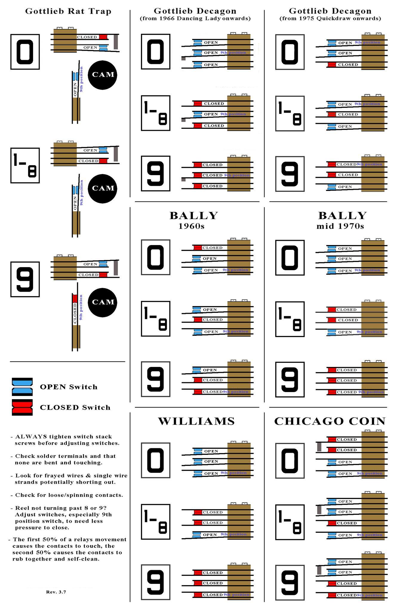
The 50/50 Rule!!
The 50/50 rule is probably the most important thing you can abide in EM repair.
Simply put, it means 50% of the switch's movement should happen
before there's any contact (in the case of a NO switch.) And the last
50% of the switch's movement should be touching the non-moving switch
contact. This ensures proper movement and "self cleaning" of the switch contacts.
Just remember the 50/50 rule, and your game should be happy and stay working.
The self cleaning Over-Wipe switch contact theory.
Cleaning (Filing) the Contacts.
Dirty and mis-adjusted switch contacts are the major cause of
all EM game problems. Fixing an EM will require some switch adjusting
and perhaps some switch cleaning. Though frankly i can go many many
EM game repairs without ever cleaning a switch... remember the 50/50 rule,
and you won't need to do any switch cleaning... because switch cleaning
can often result in unpredictable outcomes.
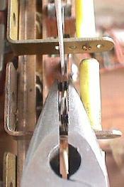
Filing a switch in tight quarters, using a flexstone and a small screwdriver
to apply pressure to the contacts.
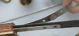
Filing an EOS switch in tight quarters, using a metal file.
To clean (file) switch contacts, use a Flexstone file or a small metal point file.
Also 400 grit sandpaper folded into strips will work in a pinch.
Do not use an Emery board! It is too course and leaves sand
chunks behind between switch contacts, potentially causing them to
not "make" (conduct). A flexstone (available from Pinball Resource)
is the best file. But a small metal ignition file should be used
on tungsten EOS flipper switch contacts and flipper cabinet switch contacts
(tungsten contacts are very hard and will wear out a flexstone quickly.)
Always power off the game before cleaning contacts.
Put the file or flexstone between the two contacts to clean, and file them.
The two switch contacts will need to be held together with
fingers or needle nose pliers or a small screw driver
to get ample pressure against the contacts to file them. Don't hold
them too tight or the switch blades could distort and bend.
The metal contact pads should be shiny and clean after cleaning.
Don't over-file the contacts, because this will change the
adjustment of the switch (because the contacts are now thinner.)
Using needle nose pliers to hold
two contacts together while filing
with a flexstone on a Gottlieb
reset bank.
Often, especially on relay switches, the adjacent leaf blades
will be so close together that you can't get ample pressure
against the file to clean the contacts (fingers won't fit!)
In this case, use a small screw driver to put
pressure on one of the contacts. Sometimes manually activating
the relay by hand helps apply pressure to the contacts
for filing.
Other times using fingers or a screwdriver to get pressure on the contacts
for filing won't work. For example, on Gottlieb game feature and
reset banks, there just isn't enough room. Instead
use needle nose pliers. Just gently
hold the two contact together with the pliers and the flexstone
between them.
Switch Contact Cleaning (Filing) WARNING.
Often I hear this from EM newbies: "I cleaned the switch
contacts and now the game doesn't work at all!" This
happens because of the way the contacts were filed.
The two switch contacts need to wipe each other with the
face of the switch contacts making solid and flush connection.
If the contacts are filed at a slight angle (which is *really*
easy to do), when the switch is operated one switch
contact may not mate with the other contact face-to-face.
That is, one switch contact face may be at a slight angle and not
flush to the other contact as the switch closes. This decreases
switch contact surface area and makes the switch fail easily.
So what can be done to prevent this? Experience! And also file
the switch contacts so they are in a "natural" closed position
(and not a forced or obtuse closed position). This is why
I am very hasitant to tell newbies to file switch contacts in EM games,
as it is very easy to file switch contacts incorrectly and make
problems worse.
Silver Contacts versus Tungsten Contacts.
Most switch contacts are made of silver. These contacts file fine with
a flexstone. But the contacts on the flipper button switches and flipper
EOS (End of Stroke) switches have tungsten contacts. These contacts will have to be filed
with a small metal file, or removed from the game and
filed with a standard metal file. Tungsten contacts will wear out
a flexstone in short order; the flexstone just can't cut them.
Note that during the 1970's, Williams and Bally started using
tungsten contacts on pop bumper and kicking rubber
switches too.
Self-Cleaning Contacts and Types of Switches.
All EM leaf switches have a "wiping" action to them: the short blade
contact is stationary, the long blade moves and makes contact
with the stationary contact. As it makes contact, the
switch will continue through it's stroke and wipe itself
on the stationary contact. This is known as a "self cleaning"
switch. For the self cleaning to work, as the contact come together,
the stationary blade must be moved a bit by the other moving blade as it touches.
Of course this doesn't happen all the time, but it should.
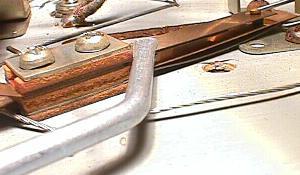
Shiny clean and smooth EOS contacts after filing.
With this in mind, adjust any switch so it has this wiping
motion. Normally Open (NO) switches should have about a 1/16"
distance between the contacts. And as the two contacts touch,
they should continue to touch and "wipe" as the switch
continues through its stroke.
Normally Closed (NC) switches should be adjusted the same way:
make sure as the switch opens and closes, there is
some wiping action. A 1/16" contact distance when open
is desirable in most cases.
Make/Break (M/B) switches are the toughest to adjust. They have
about the same amount of travel as the normally open and
normally closed switches, but have two contacts to make
and break and wipe clean. Adjusting these is more difficult.
The best method of switch adjustment is this: adjust the switch blades so that
the contacts either open or close at the half way point of their operation.
This will give the most reliable, self-cleaning action. This holds true
for relays and playfield switches.
Damping (Pre-Tensioner) Switch Blade.
On playfield switches, there is a third, shorter switch blade
sandwiched between the two contact blades. This damping or pre-tensioner blade
provides support to one of the contact blade, so the switch
doesn't "bounce", and so more spring tension is provided.
But sometimes these damping blades get bent
and short out to the other adjacent blade. Be aware of this.
When you adjust a switch with a damping blade, you must adjust
both the short contact blade and the damping blade together.
Accessing the General Health of your Switches
(Why do switches get out of adjustment?)
Every EM switch stack consists of metal blades, and bakelite insulating spacers.
With time and changes in humidity and temperature, the bakelite spaces
can expand or contract. When this happens, the spacing on the switch blades
will change. Also repeated closing of a switch thousands (if not millions)
of times can persaude the moving blades to open the switch gap a bit.
When I am working on an EM game for the first time, I like to access the
general health of the switches. This is easy to do; just try tightening
a couple different switch stack screws. If the screws are generally tight,
the health of the switches is probably good! If the switch stack screws are
loose, this means you will no doubt be doing a fair amount of switch adjustments
(the bakelite has shrunk with time, changing the gap in the switch blades).
This is good information to know, BEFORE you start adjusting any switches!
Also, if the switch stack is not tight, the bakelite
insulators can become damaged with humidity (because moisture has greater
access to the bakelite spacers). So keeping the
switch stack tight is a good idea.
Note the adjustments made to the switch stack will not be forever consistent.
At some point (could be many years!), the stacks could
"loosen" again, and switches will probably need re-adjustment.
Tightening a few different switch stack screws in
the game will give you a general idea of the game's switch health.
If you found a few loose, keep this in mind.
Since your sample is loose, the whole game will probably need more switch attention.
Using a contact adjuster to adjust the short blade of a switch.
Tighten the Stack BEFORE you Adjust!
If a switch needs adjusting, tighten the switch stack
before starting. Since tightening the switch stack
will change the spacing of the switch blades, don't
forget to tighten the switch stack BEFORE adjusting
the switch blades!
When tightening a switch stack, it is best to tighten the screw closest to the switch contacts
first. Though this is not a big deal, this is what Gottlieb recommends.
If the switch stack is really loose (or the switch stack was disassembled to
replace a blade), alternate the tightening of the screws. That is, tighten
one screws a turn or two, then change to the other screw. Be careful not
to kink the metal switch blade, and not to crush a bakelite spacer.
Adjusting Switches.
The best method of switch adjustment is this: adjust the switch blades so that
the contacts either open or close at the half way point of their operation.
This will give the most reliable, self-cleaning action. This holds true
for relays and playfield switches.
Note the Damping Blade: this playfield switch has a third shorter
blade between the contact blades to provide support. Make sure these
damping blades don't short out against the adjacent blade. And remember,
don't adjust the long blade. Adjust only just the short blade, and the
damping blade (if the switch has one).
Adjust the short (stationary) blade contact only (and the damping blade
if the switch has one). Put your contact
adjuster on the short blade (and the damping blade), and slide it down to the bakelite
insulator stack. Bend the blade gently! A small adjustment of
just a few thousands of an inch is all that is required. If you are
making large adjustments, you are probably doing something wrong!
(or someone else previously mis-adjusted the switch;
large gross adjustments at the switch stack could break the switch blade).
Usually the only time the long (moving) blade of a switch will ever be adjusted is if
someone before mistakenly did this. Otherwise the moving blade
of any switch should not be adjusted. There are some exceptions to this.
For example, make sure the moving blade
is pressed against its activator (a wire form for rollover switches,
or armature for relays). If it is not against its activator,
then the moving blade will need to be adjusted. Having the moving blade against
its activator can make a big difference, especially on Gottlieb relays
that have a very short switch throw. On relays, look at the blade where it is
inside the armature slot. If the blade is at the "bottom" of the slot,
the blade will have *less* travel (and hence the switch will be less reliable and
harder to adjust). Those blades at the "top" of the slot
will move the most when the relay is activated, and all moving blades should be
adjusted to have the most travel. Note this is not for the faint of heart. If
there are any doubts, don't adjust the moving blade!
It is important to adjust EM switches at the switch stack
(that is, where the switch blade touches the bakelite spacers).
This is how Gottlieb (and some very well-known EM game mechanics)
recommend EM switches be adjusted.
Do not adjust switches on the length of the blade (unless a previous adjustment mistake
needs to be corrected, where the switch was grossly mis-adjusted!).
The reason for this is simple;
adjusting the switch anywhere but at the switch stack will compromise
the "temper" of the switch. Every switch has a certain "temper" or "springiness",
depending on the length and thickness of the switch blade. If adjusting
the switch anywhere but at the switch stack, the temper can be compromised.
Remember, only small adjustments to a switch blade is being made. If someone
before really mis-adjusted the switch,
and very large switch adjustments are required, this may have to be done
over the entire length of the blade. But for normal switch
adjustments, adjust the switch blade (gently and slightly) closest to the switch stack.
It should be noted that Williams recommends switches be adjusted across
the length of the switch blade. This is contrary to what Gottlieb recommends.
My feeling is unless correcting someone else's adjustment mistakes,
adjust the switch at the switch stack only. The "temper" of the switch is
important; this determines how much "spring pressure" the switch puts on
its associated parts. If adjusting the switch blade along the length
of the blade, this can change the temper. On relays, this can cause a relay
to not work properly (if the spring pressure is reduced), or to "buzz" loudly
(if the spring pressure is increased). For this reason, only adjust switches
at the switch stack.
A Mis-Adjusted Playfield Switch: Notice the damping blade in the middle
(which dampens the upper contact) is shorting to the lower contact.
Yet the contact pads are adjusted correctly. This is visually deceiving.
Fish Paper.
Fish paper is the insulating gray
paper seen between switches, mostly in switch stacks. It prevents
one set of switch contacts from shorting against another. Often this paper
gets worn and damaged. This can cause adjacent switches to short.
Inspect the paper, and replace where necessary.
A Good Reason to Inspect Every Switch.
One of the reasons I tell people to inspect every switch is that
things you would not normally see become obvious. Stuff
like missing switch contacts, broken switch blades, broken
switch wires, etc. All these things are very obvious if you
have inspected every switch. This is a systematic and proactive
way of repairing these games. If you don't understand
EM schematics very well, this can be an incredible time savings.
If you found an obviously broken switch while cleaning,
finding the same broken switch because the game doesn't work
using schematics tends to be A LOT tougher, and a lot more frustrating!
Can you see the missing switch contact on the switch blade? This one
easily found problem during switch cleaning could have been the only
thing preventing the whole game from working. Yet if every switch
was not cleaned and inspected, this would have been over looked. Then
a process of tracing the game's schematics is the only repair method
(which proves to be a lot more frustrating for an EM newbie). This
problem can be easily repaired by sanding the switch blade, and
soldering in a new switch contact (the tension of the switch blades
against each other can hold the new contact in place while soldering).
Think BEFORE Adjusting! Let's repeat that:Think BEFORE Adjusting!
If adjusting more than about 5% of all switches
on an EM game, you are probably doing something wrong!
Stop now before troubles become worse. Unless
the game has been mangled, adjusting more than 5 switches
out of 100 is very unlikely. See the above "Word of Caution"...
A "Quick Fix" Idea - Working in the "Dark".
There is an old trick that
can be used to find problem switch(es) in an EM game.
For example, one reader explained this problem:
"My Williams Spanish Eyes machine had an interesting problem when I
first got it. Just before the first replay value of 50,000 points (at
40,000) the replay knocker would begin to rapidly fire for several
seconds...It sounded like a machine gun firing! It did this every time
at 40,000 points. It seemed like a switch could be out of adjustment and
oscillating, causing the knocker to 'machine gun'."
At this point, most people would get out the
schematics, and hunt down the problem.
But wait a minute! Why not turn out the lights and look
for the infamous "blue sparks" to find the trouble switch(es).
In this example, the reader ran the game up to
39,000 points with the playfield up and the back box opened up, then
turned out the lights. Only then was the last 1,000 points scored
manually with the playfield glass off. The knocker
started to 'machine gun' again, and right in tune with it was a display
of blue sparks coming from a switch controlling the thousands scoring.
In this example the
switch blades were adjusted too close together. Two minutes later the
problem was fixed. The schematics weren't even needed.
This technique can be used to find direct shorts too.
Just a warning though: this "dark room" technique certainly
won't help fix every problem. And on games that are completely
dead, it won't help at all.
2g. Before Turning the Game On: Score Reels and Score Reel Relays
A Big Problem in EM Games.
Think about it: what's the most used (abused!) device on any
EM game besides the stepper units? The score reels! (Note: if a 1950's
game without score reels, skip to the Stepper
Units section.) The score reels move for every point scored, hundreds of
times per game.
If the score reel contact points are mis-adjusted, the game
will never complete its start-up sequence! This is definitely the most common problem in
EM games. It's pretty easy to identify this problem too: press the "start"
button on the coin door, and the score motor in
the bottom of the cabinet "runs." It never stops, and the
game never starts.
The reason the score motor is running is the game doesn't think the score reels
are reset to the zero position. This happens for a bunch of reasons,
but usually it's because the zero position switch(es) are out of adjustment
or dirty (though sometimes it can be as simple as a wire broken off the
score reel solenoid or score reel edge card or zero switch, or the solenoid is dirty and sticking).
All Score Reels are Very Similar.
During the 1950s and 1960s, all the game manufacturers seemed to
use the same score reel "guts" (exception: 1965 to 1975 Midway games
used motor driven score reels instead of a solenoid driven -
see the next section for information on those.) The only major difference
between the other various game makers was the rotating reel itself.
The rotating reel on Gottlieb and Williams games
was aluminum with the numbers screen printed right on the the reel. Genco
used an aluminum reel also, but the numbers were printed on a paper
reel cover. Chicago Coin uses plastic reels. (Which by the way are
*very* easily damaged if cleaned. Only use Novus2 to carefully clean
the plastic reels. A water solution will remove the numbers!)
The other difference in score reels between manufactures is the
sometimes used "circuit board" on the score reels. This circuit
board is used for the match and high score sensing (so not all
reels or even all games will have these).
The point I'm trying to make is score reels are basically
all the same. Here is what they all have in common:
A stepper solenoid to advance the reel.
A zero position switch which opens when the reel is at "zero".
This is used in the game's reset process to set all the score
reels at zero.
A nine position switch which closes when the reel is at "nine"
(not all reels will have this, as this switch is used to advance the
adjacent reel).
An EOS (End of Stroke) switch which closes when the score reel
solenoid energizes (again not all score reels have that switch).
A circuit board with a rotating "finger" to sense where the
score reel is currently set (used for Match and high score circuits).
This is not on every score reel or every game.
Sometimes there will be other switches or components on the score
reels too, but above are the most common.
Score reels and their switch configurations during resets and carry overs,
for various makers and time periods.
Removing a Score Reel.
Each score reel will have some easy mechanism to remove it from
the backbox. On most Gottlieb, Williams and Genco games up to 1967,
the "rat trap" reels have
a small "hairpin" that must be removed. Chicago Coin used two
screws to secure each reel. On 1967 and later
Gottlieb "decagon" score reels, there's a nylon release tab.
1970's Bally and Williams have small levers that are held to remove
the score reel. Whatever the game, there will be some mechanism that
allows easy removal of the score reels for service.
Checking for Mechanical Problems.
With a reel removed, manually press the coil plunger in and let go
quickly to release it. (Do this quickly;
if the plunger is let out slowly, there may not be enough
momentum to move the score reel to the next digit.) Does the
reel move easily to the next digit? If not,
disassemble the mechanism and clean the moving parts with
alcohol. Typically the plunger inside the coil is gummed
up. Note: do not lubricate the coil plunger! It's
a dry system, no lubrication (which just attracts dirt) needed!
If someone before lubricated the coil plunger, this
may be the problem! Clean it.
Also check the return spring tension. The return spring pulls
the coil plunger mech arm back after the plunger pulls in.
It has to do this with enough spring strength to move the score
reel to the next digit. Sometimes these springs are old and
tired, and need to be replaced (in the short run you can cut 1/2"
cut off to temporarily rejuvenate the tension.)
Before doing that, make sure the mechanism is clean
(see previous paragraph.) Increasing the spring tension on
a dirty, sluggish mechanism doesn't really help anything!
Manually Moving the Score Reel.
A score reel can be manually moved by pressing in the
score reel coil plunger by hand. Use fast concise movements
to emulate a coil pulling-in the plunger. Do not wrench
on or try and rotate the score reel cage itself. This will damage the mechanism.
For a test, turn the game on and try
to start a game. Do the the score reels move to zero?
If not, try manually moving all the score reels to the
zero position. Now try starting a game; does
the score motor stop running? It may or may not, depending on what
is wrong. If the switches are out of adjustment or dirty, the score
motor may still run. If the game starts after manually moving the
reels to zero, just cleaning the
score reel mechanism so they could turn easily may fix the game!
1970s Williams Score Reel (Space Mission): note the zero and nine
position switches at the lower left. The 1970s Williams and Bally score
reels are very similar, but have no exchangeable parts.
1970s Williams Score Reels: shown here are the two varieties of Williams
score reels used during the 1970s. The larger version (bottom) is older.
The smaller version shares very few parts with its larger cousin.
1960s Bally Score Reel: note the zero and nine position
switches at the left on this Bally unit.
1970s Bally (lower) versus Williams (upper) score reels:
they sure do look the same, but they are not. No common parts shared unfortunately.
A 1960s Gottlieb "rat trap" score reel with no printed circuit board (easy switch
cleaning and adjustment; no dis-assembly required).
1950s Genco and Chicago Coin score reel. Essentially the same mech as a
Gottlieb/Williams rat trap reel, but with a different paper covered numbered
aluminum reel (Genco 2 Player Basketball).
1960s Chicago Coin score reel. Notice the plastic reel which is easily damaged
during cleaning. Also note the different style of score reel circuit board.
1970s Chicago Coin score reel. Notice the stepper unit like fingers across
the bakelite circuit board. There are no other switches on this score reel
other then these stepper fingers. If the two fingers on the top side of this
photo are not making good contact to the bakelite disk, the game will never
know that the score reel is at zero (and the score motor will continue to
run when the game is reset.) Notice the burn on the circuit board that is
starting (blue arrow), which will eventually ruin the circuit board trace.
This will make it impossible for the game to "see" the zero reel position.
Score Reel Switches.
If the game still won't start, it's a good idea to examine the score
reel switches. Clean and maybe adjust the zero position or nine position
switches. All score reels will have some sort of cam that opens and closes a set
of switches as the score reel moves to the nine and zero positions.
On 1970's games, this is real easy to find. These switches are
on the outside of the reel, and easily seen. On early "rat trap" Gottlieb score
reels this is a bit more difficult. Score reels with
printed circuit boards on the outside will need to be disassembled
to get at the switches (see pictures).
Starting in 1967, Gottlieb switched to the "decagon" score reels (the reels
themselves are a decagon shape, and are not round). The switches
on these units are much easier to access.
A Gottlieb "rat trap" score reel with printed circuit board
(dis-assembly required to clean and adjusts the switches,
which live under the board).
An early version of the Gottlieb Decagon score reel, with the 10 sided
flat face score cage. This was only used for a couple years starting in 1967.
(Gottlieb Target Pool.)
A Gottlieb "decagon" score reel, as used in the 1970s.
Note the switches are much easier to access, even with the
printed circuit board in place. Also the reel cage is now round.
Once there is access to the zero and nine position switches, manually
move the score reel solenoid. Note how the switches operate, especially
when the reel is at the nine and zero position. If it's not obvious what
is happening, compare to a functional score reel to figure it out (this is
a very handy trick, assuming at least one of the game's score reels
is working and resetting!)
There is also a nine position switch on all the
score reels (except for sometimes the last, largest number reel).
When the score reel is in the nine position, it closes one or two switches
which tell the next score reel in line to move up one when the current
score reel advances to zero.
Gottlieb Decagon Nine, Zero Position Switches:
The decagon score reels provide easy access to
these switches for cleaning.
The zero position switch(es) tell the score motor when the score reel
is at the zero (reset) position. There is usually two sets of zero position
switches: one for the score motor, and one which enables the score reel's solenoid.
Clean all the nine and zero position switch with a flexstone. And make sure they operate
with a good wiping motion, and adjust accordingly.
But be careful in adjusting the zero and nine position switches.
There is a balance between switch blade tension and the amount
of "horsepower" available to turn the score reel. If
the switch blades have too much tension, the score reel may
"hang" and not move past the nine or zero positions. This is
a common problem, and some (incorrectly) change the return
spring tension to try and compensate for it.
Lastly, many score reels have a score reel solenoid EOS (End Of Stroke)
switch. Make sure this switch opens when the score reel solenoid is
fully engaged. Also clean this switch. See below for more details on
this switch.
Gottlieb Decagon Tricks.
Note there are some other things to think about on Gottlieb
Decagon score reels. First is the backwards latch. This prevents
the score reel from moving backwards when it tries to advance.
It's common for this to get bent, allowing the reel basket to
move backwards instead of forward. A simple bend of this latch
so it rests against the basket's inside wedge teeth often
fixes a lot of Decagon problems.
A Gottlieb "decagon" score reel showing the parts you'll have to deal with.
Notice the "backwards latch". This is often bent out of place, allowing the reel
to move backwards and not advance forward. A simple bend of this latch can fix
a lot of Decagon problems. Also note the return spring. There's a "cheat" that
can fix a lot of problems by modifying this spring.
Taking apart a Decagon score reel is different than other
reels. Frankly it's somewhat intimidating, especially on
reels with a bakelite match/replay score disc. For those
reels that are "sluggish" (and frankly should be taken apart
and cleaned), there is a "cheat." That is, you can shorten
the plunger return spring about 3/8". This takes just a minute
using a hemostat and wire cutters (compared to 15 minutes to
completely disassemble and clean the score reel.) It is a cheat,
so it's not the right way to do it. But sometimes the path of
least resistance isn't so bad after all...
Gottlieb "Rat Trap" Reel: Remove the three screws so the metal score reel
can be removed from it's cam. Do not remove the retaining clip from the
cam shaft! With the reel removed, use some 400 or 600 grit sandpaper and clean the
printed circuit board traces so they are shiny. Note the one larger alignment pin
(blue circle) on the nylon hub. This lines up the score reel's larger hole (blue
circle) when replaced. But don't get the alignment holes mixed up with the three
(like sized) screw holes!
Gottlieb "Rat Trap" Reel: with the reel cage removed, it's easy to see
the nine, zero position and EOS switches.
Cracked Solder Joints On Williams Score Reel Switches.
Williams games have a particular problem with cracked solder joints
on the wires soldered to the score reel switches (zero, nine and EOS
switches). This happened because of an inferior manufacturing technique
William's used to attach wires to the solder lugs.
This can cause game reset problems. It's a good idea to
pull on each wire going to these switches to check for cracked
solder joints. It's almost a guarantee to find at least one
wire with a cracked joint on any Williams games. To properly
fix this, cut the wire(s) clean and twist together. Heat them
with your soldering iron, and apply some solder. Now heat the
solder lug on the score reel and flow the tinted wires into
this joint. A smooth joint will not break.
Clean the Score Relay Switches.
Each of the score reels is driven by an associated relay.
Since the score reels get considerable use, you can also
assume the relays that drive them do too! Because of
this, clean ALL the contacts on each score
relay. There will be about five switches (more or less) per relay.
At least two switches will activate the score reel itself (and
maybe the next reel in the line for when the current reel's score moves from "9"
to "0"). One of the switches will probably go to the bell solenoid for that
score reel. Clean all the switches with a flexstone. Also
check that the switches are adjusted correctly with a
good wiping motion (as described in the switch contact
section).
Bally Score Reel Relays: the three relays at the left score the points for the
10, 100 and 1000 point reels. Each relay has a switch for the score reel, the chime,
the next up score reel (for when the current reel is at the "9" position so it
can also advance the adjacent score reel), and possibly a switch for a 00-90 unit
(if the 10 point score reel) or some other game feature that toggles with a score
reel. The 10,000 score reel only gets advanced when the 1000 point relay hits "9",
so it doesn't need its own relay. The two relays on the right are used to reset the
score reels when a new game is started - One relay resets two players or eight reels
(4 Million BC).
The Score Reel EOS Switch.
Each score reel will have an end-of-stroke (EOS) switch for its
coil. This normally closed switch will open as the coil plunger
reaches its end of stroke when advancing the score reel.
The EOS switch's purpose in life is to break the power going to
the score relay. If this switch never opens, a score relay can
stay energized (stuck on). This can lock on the score reel coil on (energized)
and any feature (such as a bell or chime) wired to the score relay.
This EOS switch should be cleaned and adjusted properly.
If a score reel EOS switch does not open,
it will cause problems (particularly on Bally and Williams games),
keeping the score relay (and score reel coil/chime coils) energized.
However a broken, permanently open, or missing score reel EOS switch
causes far less problems.
The score reel EOS switch keeps the score relay energized for
a longer period of time (increasing the score relay's pulse length
for the things it is controlling). A broken EOS switch
can mean if a playfield target switch is activiated quickly, the
pulse train may not be long enough to score the points (or features)
for that target.
What about a missing or broken score reel EOS switch? In reality
this is usually Ok, and very common. Often one of the blades on the EOS switch
breaks off (from constant use). This leaves the circuit permanently
open. Again, this is Ok in most cases. The only problem that can occur is if
the EOS switch becomes permanently closed, not open! If there is
a broken score reel EOS switch, just forget it until the game is
all working (then go back and fix it). Having a broken normally closed EOS switch
blade only makes the pulse slightly shorter for the score reel to move
to the next position.
The exception to this is if the EOS switch is a 3 blade make/break switch or
a normally open switch. In this case it is performing a carry function
and is critical.
Note that 10,000 point score reels usually do not have a score reel EOS
switch. Since the 10k score reel is controlled by the carry-over
"9" switch on the 1000 score reel, a 10k score reel does not need an EOS switch.
Testing the Score Relays.
Once the score relay switches are filed clean and adjusted, test them.
(Even if the game is a 1950's EM with no score reels, it still has
score relays that connect to the score stepper units instead of
score reels.)
On Gottlieb games, the score
reel relays can only be tested during a game.
On Williams and Bally games, just turn the game on.
Manually push each one of the
score relays in by hand. The score reel it controls should
advance. Note: when doing this in "game over" mode, if "0" is reached on
the score reel, it will NOT advance the next score reel.
But if you do this test in the middle of a game, when
a "9" is reach, manually pressing the score relay again will
advance the next reel one step too.
Gottlieb "Rat Trap" Score Reels and Relays (Buckaroo):
Notice the three relays to the right which control the three score reels.
("L" is 100s, "M" is 10s, "N" is 1s, "F" is the credit relay.) Since this
game has a lighted fourth "one thousand" score, there is one relay for
each score reel (unlike the picture of the above Bally relays where one
of the four score reels doesn't have a corresponding relay, and is merely
triggered by carry over switches.)
When starting a game and manually testing the score relays,
check the "9" position of each reel. That is, advance
a score reel to the "9" position. Now activate the score
relay again. Does the next score reel advance with the current
reel? If not, the "9" position switch on the current score reel
may be dirty or out of adjustment (or the highest score
reel in the numeric set is being tested!)
Remember, on Gottlieb games, the score relays can only be tested during
a game. So if a game cannot be started at this point,
the score relays cannot be tested. This is unfortunate, but there isn't
any alternative.
The "Art" of Manually Activating Relays.
As dumb as this may sound, there is actually an "art" to
activating a relay by hand. If done incorrectly,
the relay can be mis-aligned, and seemingly make a working
relay into a temporary mess.
Each relay has the coil itself, a pivot point, and
a metal activating lever plate with a plastic or bakelite piece that
the switch ends ride in. To activate a relay, press
the metal plate in towards the coil. But be careful,
if pressed with a sideways motion or pressed too hard,
the metal lever plate can be knocked off its pivot point.
This will mis-align the switches and cause chaos.
It's easy to fix, but the mis-alignment may not be noticed,
and all the switches in this relay will look like they
need adjustment (when in fact they do not)!
Score Relay/Score Reel Stuck On?
This is a common problem. One of the score relays is stuck
"on" as a game is started. A lot of times people don't
notice this until they smell the score reel solenoid burning!
A sure sign of this is a score reel doesn't register points.
This happens because the score reel solenoid and the score relay are
both pulled in and won't release.
Check all the playfield switches; one is probably "on", thus
locking it's corresponding score relay on. If a closed playfield switch
cannot be found, it could also be a feature relay
switch that is stuck on. For example, the fifty point relay
has a stuck switch which connects to the score relay.
To really know if the playfield is causing the problem, the playfield
connectors on the bottom panel can be removed, taking the entire playfield
out of the equation. (Yes all 1960s and later EM games with score reels
will start and run without the playfield installed in the game.)
In my experience playfield roll over switches get stuck "on"
often (usually from dirt or wax getting caught in the roll over,
leaving it permanently engaged.)
Playfield side: Star roll over switches on a 1976 Bally Captain Fantastic.
It's very common for these to get stuck down from playfield dirt or wax, causing
(in this case) the 1000 point relay/score reel to stick "on", along with the bonus
stepper unit! (This is the trifecta of burn, you get three coils burnt from one problem.)
Under Playfield: Star roll over switches on a 1976 Bally Captain Fantastic.
These switches have very light (thin) switch blades, and are easily bent or
mis-adjusted so the contact points get stuck together.
Some other things that cause a score reel to stick "on":
Score Reel EOS Switch is dirty or permanently closed (see
above).
Two solder lugs of a switch are bent and shorting together.
A single loose strand of the multi-strand wire is broken and bent,
shorting to another solder lug.
The vibration damping blade is shorting against the other adjacent switch blade.
Pitted or mis-adjusted contacts driving the score reel. Until the score
reel takes its step, it won't release the score relay.
A stuck (closed) playfield switch, which locks on the associated points
relay, and hence locks on the score reel.
A Mis-Adjusted Playfield Switch: Notice the damping blade in the middle
(which dampens the upper contact) is shorting to the lower contact.
Yet the contact pads are adjusted correctly. This is visually deceiving.
Of the above listed problems, the last one is the most common! A lot
of times you just don't noticed it. If you look at a playfield
leaf switch, you'll notice it consists of two leaf blades
with contacts. BUT there is a third, shorter blade. This blade is
the vibration damping blade. It provides support to ONE of the blades.
Yet sometimes this damping blade is bent and shorts against the other
blade. This will lock a score relay and/or feature relay on.
2h. Before Turning the Game On: Video of Score Reels used in EM Games.
Movie of EM Pinball Score Reels.
Below is a 5 minute movie I made of the
various EM pinball score reels.
This is a 640x480 movie file.
2i. Before Turning the Game On: Midway Motorized Score Reels
(1965-1975)
Starting around Mystery Score (August 1965) to about 1975 (when Midway largely
converted to solidstate score displays), most (if not all) Midway pinball and
arcade games used motorized score reels. I don't really understand why they did
this, but it must have been some attempt at "making a better mousetrap". Unfortunately
Midway did not succeed (at least in my opinion).
The conventional solenoid driven score reels as
used by all other game manufacturers were easy to work on and well understood
by any decent game repairman. Midway's system was unique and not easy to
understand or work on. They didn't really use less moving
parts, and they weren't more reliable. When the motors overheated and burned it
wasn't as simple as replacing an inexpensive solenoid to fix it.
For these reasons there are some people that avoid 1965 and later Midway games
because of the motorized score reels.
Personally I find the unique game play of the 1965 to 1975 Midway games
irresistable. For this reason, I have a love/hate relationship
with these motorized score reels.
How They Work.
The score reels move using two motors (or "score motors" as Midway calls them, just to
confuse people with the bottom panel score motor used by other makers - I call
them "score reel motors" to avoid confusion). There are two motors that controls
all three (or more) score reels for one or two players. The
two score motors are placed right next to each other in the
horizontal center of the backbox, but act independently (though they appear to be
a single motor). One motor spins the reels forward, and the other motor
spins the reels backwards.
The system works like this: There is a relay latch mounted
towards the back of the score reels. The relay latch work on
the "ones" (or lowest denominator) score reel. The other score reels
(tens, hundreds, etc) also have a latch plate just like the ones reel,
but no relay to control it. Each score reel also has a simple clutch,
so that the reel can stop spinning while the score reel motor continues to spin.
When the game is reset, the *reverse* rotating score reel motor
turns due to a switch that closes on the start relay.
All the score reels move to zero and then lock in place because of a groove
in each score reel, which stops the score reel from spinning on its latch plate.
The score motor continues to turn in reverse for a pre-determined
length of time (determined by the game's "feature motor", which is the
same thing as any other maker's score motor). If any score reel hits zero
before the score reel motor stops turning, the score reel stops spinning on the
score motor's rotating shaft because of the reel's clutch.
Now that all the score reels are reset to zero, whenever points are
scored, it is done by turning on the *forward* rotating score motor.
This will move the lowest denominator (one's) score reel. Timing is used
based on the score reel motor and feature motor's known RPM speed to
achieve a particular score, in conjunction with the score reel's latch
relay (which pulls in, and allows the score reel to turn) and the score
reels stepper-unit-like fingers on a bakelite disk.
The tens, hundreds, thousands reels only
move as the previous reel hits nine and advances back to zero.
A set of Midway motorized score reels. Note the slip coupling that mates the motor
shaft to the score reel shaft. Also note the latch plates for each score reel.
Game: 1965 Midway Mystery Score.
Working on the Motorized Score Reels.
At first it seems like an ingenious system, until you have to work
on one! Usually each score reels has a pair of "fingers" which
move across a bakelite disk, like a stepper unit. Often these bakelite
disks and fingers need to be cleaned. Or the score reels do not have
the proper "shaft slip" (clutch) for them to reset to zero. Or worse, the
score reel motor burns. If any of these happen, the score reels need
to be taken apart.
Nearly all the Midway games with the motorize score reels run the motor
during the entire game. And a system of leather clutches slip, so the
score numbers do not move. WHen a relay releases for a timed interval,
the score reel moves 1 (or more) numbers. The key is the leather clutch
system. In addition there's also nylon slips too. These all need service.
But the leather clutches are the majority problem. The leather dries
with time, and needs Neatsfoot oil to stay soft and slippery.
The good news is all this can usually be handled without taking the
reel system apart. There's a center spring, allowing the score reels
to be slid on the score shaft, and the leather/nylon clutches to be
cleaned and oiled.
Taking apart a Midway score reel is where things get tricky, and I must warn you...
DO NOT DISASSEMBLE THE SCORE REELS UNLESS YOU ARE SURE THEY
NEED TO BE TAKEN APART. It is really easy to mess up the whole
clutch system, so don't take them apart unless you must.
In addition the bakelite disc are easy to mount incorrectly
or in reverse, making the entire game a pile of non-working headache.
Again, DO NOT take the score reels apart unless you must!
A set of Midway motorized score reels from a Bulleye Taget game.
Slide the reels into the spring, giving you room to service the leather
and nylon slip clutches.
The blue arrow show the nylon Midway #35-908 motor coupling. Do not loose or break this!
They are hard to get. Luckily though, you can 3d print this part. See below for more info...
The first trick is removing the reels
from the backbox. Tilt the backbox insert panel back. This
will allow easier access to the difficult-to-access four machine screws
that hold the set of score reels to the mounting base plate in the backbox. After the four
screws are out, the whole set of score reels can be slide up and back.
This happens because of a slip joint between the score reel motor
and the score reels.
At this point, STOP AND THINK. Any disassembly of the score reels is
VERY risky. If not put back together correctly, the whole set of
score reels will not work. It is *very* easy to make a mistake!
DO NOT take the score reels apart unless you have a darn good reason.
Chances are excellent you will only make things worse.
Now examine the set of score reels. Is the nylon #35-908 motor coupling
in place, or is it missing? (See section below.) Are any wires
cut or broken off the relay or bakelite plates?
Does the latch relay look to be in good condition?
Do the reels seem to move without binding when the latch plate is
engaged or disengaged, in either direction?
Usually any of these problems can be fixed
without any disassembly of the score reels. The only thing that really
can't be worked on is the cleaning of the score reel "fingers" and
the bakelite plates the fingers ride.
If the score reels must be taken apart, take good notes and lots of pictures! This is
very important. Also start on the side of the score reels *with*
the locking "E" clip. Remove the clip and the two screws that secure
the end plate. Then remove each notched
washer, spacer, score reels, and bakelite plate. Make notes of how
and where each part was removed. Stack the parts in order, making it
easier to reassemble. Clean the score reel fingers and backlite plates
with 400 or 600 grit sandpaper. The bakelite plates can be lightly lubed with Super Lube Gel.
Reassemble it all, making sure not to
mess up the order of the parts. Soak the leather clutch in Neatsfoot oil.
Pray that you did it all right.
A major problem with Midway motorized score reels is the nylon coupling (#35-908).
This moves the power from the motor to the reels. Because this part is plastic, it breaks.
These are hard to find.
Blue arrow: nylon coupling. Red arrow: missing coupling!
Midway Motorized Score Reel Parts.
The one part that breaks on Midway score reels is the nylon coupling
gear #35-908. If this part is gone, there is no way for power to be transfered
from the motor to the reels. And because they are nylon, they do break
down over time. The good news is that I have 3d draw this part, and
you can download the Midway Score Coupler STL file
and print it with PLA plastic on your 3d printer. It actually works quite well!
Midway motorized score reel with a new 3d printed nylon coupling #35-908 installed
(the part in my hand is an original.)
You can download the STL file and print it on your 3d printer.
Burnt Midway Score Motor Rebuild.
If someone turned on a Midway game without checking/cleaning/servicing
the score reel assembly (for example, treating the leather clutches with
Neatsfoot oil), the score motor can die quickly. If there's too much
resistance in the score reel assembly, and the motor can't spin the
shaft, the motor *will* burn. This is common in Midway games that have
been stored poorly, and the leather clutches have dried out (or the
lube used on the nylon slip parts has solidified.)
Midway motorized score reel on a Midway Bullseye/Golf Champ game.
Assuming you can deal with the leather/nylon clutches, but the motor
is burnt, you will have to either replace the motor core, or rebuild
it yourself. The Midway motors should have 10 ohms of resistance.
If it's much lower than that, the windings have heated and burnt
the enamel paint insulation off the winding, shorting them together,
and burning the windings and motor core.
Burnt Midway motorized score motor on a Midway Bullseye/Golf Champ game.
Pinball Resource can provide a new Multi-Products motor core. It's not
cheap, and it's a lot of work to replace. Or you can rebuild your existing
motor core. Not easy, but it's an option. I will show you how to do it
on a 120v score motor from a Midway Bullseye/Golf Champ game. The motor is
120volts part number 40-2105. On this series of games, there's actually
*two* motors: one that runs forward (which is the one that usually burns),
and one that runs backwards. Since these are AC motors, the core has
to be "reversed" to get an AC motor to run in the opposite direction.
Keep that in mind...
To rebuild the motor core yourself,
drill out the four brass rivets holding the motor together, which separates the motor case.
Then the winding area can be accessed. The core is a very tight slip fit, but with a punch,
you can slip it out. This exposes the motor winding that go around half of the core.
With the core separated, the old windings can be easily removed, and new windings added.
Getting ready to wind the new motor core on the 3d printed frame.
But the motor winding frame, which is nylon, often melts and burns into dust.
So what do you wind the new wire to? The nylon motor frame is absolutely need to hold the wire in place,
and insult the wire from the motor plates. You can make your own motor frame using 3d printing.
I designed a Multiproducts motor winding frame STL code,
which you can download and print on your 3d printer.
Winding wire off a Bally pinball coil and onto the new 3d printed motor frame.
With the new PLA 3d printed motor core in hand (note I later changed to PETG for the printed motor core),
next up is winding the wire. So how much wire? what wire? Well we knew an un-burnt Midway motor was 10ohm.
So I went through my pinball coil inventory, and grabbed a 26-1200 Bally -35 pinball pop bumper coil,
which is 10 ohms. The wire thickness seemed the same as the burnt coil wire from the motor.
Wind the wire off the pinball coil and onto the newly 3d printed motor frame.
Note you have to do this right... the windings need to go in the proper wind direction.
And you can't fill up the frame too much, or you won't get the motor back together. As it turned out,
the 26-1200 coil was pretty much perfect in this situation, and the new motor frame coil measure
the desired 10ohms.
The finished Multi-Products re-wound motor! Ready to be installed in the game.
Since this is a 120volt motor, can test it easily with wall voltage.
Next was to re-assembly the motor. Now the original brass tubes, which are flared to hold
the motor together, had one side drilled (so the motor would come apart.) the right way to put the
motor back together is to get new 3/16" brass tubes, install and flare them, which will hold the motor
together. I take a different approach and use #4-40 machine screws and locknuts instead.
Usually a 2" long #4 screw is fine... but this is a double motor, so I needed four 3.5" long
#4 machine screws. Therefore i TIG welded two of those 2" screws together to get a 4" screw,
and that worked just great.
Here's the version2 of my motor re-wind, using a heat cutoff switch and red PETG 3d printed plastic motor core.
The heat cutoff is placed against the coil windings,
and then black electrical tape is used to hold it in place. That's why the motor coil
now looks pregnant. If the motor windings get to 170 degrees, the switch opens, and
the motor shuts off before it can damage itself. When the windings cool, the switch
closes, and the motor is back in operation.
Note that I changed my mind on this motor rewound, and installed a heat cutoff switch and red PETG
3d printed plastic motor core. Basically the
heat cuttoff (seen in the above picture foreground) is a heat switch, put in series with the coil windings.
They come in varying temperatures, I think I'm using 170 degrees.
The heat cutoff is placed against the coil windings,
and then black electrical tape is used to hold it in place. That's why the motor coil
now looks pregnant in the picture above. If the motor windings get to 170 degrees, the switch opens, and
the motor shuts off before it can damage itself. When the windings cool, the switch
closes, and the motor is back in operation. Note also changed from white PLA to red PETG
for the motor core 3d printed plastic, as PETG melts at a higher temperature. I think using
the heat cutoff switch is really a good idea to prevent future problems.
With the motor all together, it was now time to test the motor. Using 120volts AC
(standard wall voltage), the new motor worked perfectly (60rpm), in both forward (the burnt side),
and reverse (virgin) side. Now install the repaired motor, and finish repairing the game.
But the hard part is done! This Multi-Products motor frame core should work on all the other
MP motors (like gottlieb and williams pinball score motors.)
2j. Before Turning the Game On: Misc Things to Check before Power-on.
At this point the game should have been systematically gone through, including
the following:
Fuses and fuse holders checked.
Connectors cleaned checked for proper insertion.
Coin door switches not molested.
Set to free play.
All stepper units cleaned and manually checked for proper operation.
All score reels checked.
All relay switches manually examined for proper wiping motion, broken blades,
missing contact points, broken wires, etc.
There are a few other things I like to do and look for before powering
the game on for the first time. Here's a list:
Examine all wire-to-switch solder points. Especially on 1970s EM games,
it is very common for a wire to break off a switch's solder point. This
happened because the factory often didn't heat the switch solder point
hot enough, and the solder delaminates from the switch contact point.
Especially on score reels, I like to gently tug on the wires to ensure
they are still firmly soldered to the switches.
Check for any missing nylon spacers between the score motor switch stack blades.
Check the Score Motor "home" switch for proper gap and clean the
switch.
Make sure the game is set to Free-play. When the credit unit
is at the "zero" position, make sure the switch that is Normally Open
is adjusted so it is permanently closed. Also make sure the max-credit
switch is closed (and opens at 6 or 8 or 10 credits) while you are there.
Check the coin door's coin switches. Often these switches are
accidentally jammed closed from people trying to put credits on the game.
This will make the game stay in a reset cycle. (Another reason why
I always put EM games on free-play.)
Examine all top-side playfield switches. Old and bad playfield
rubber can force playfield switches closed, making a point relay
energized (and forcing a score reel and chime energized), eventually
causing them to burn.
Examine the game's tilt plumb-bob and ball-roll mechanism.
Is the tilt jammed closed? This is very common especially when a game was moved.
Examine (or replace) the power cord. 30+ years cause cause the
rubber in the power cord to break down making the cord dangerous.
Give the game a good visual examination. Your best tool in
diagnosing and fixing EM games are your eyes! Your power of observation
will find nearly all problems on an EM game.
Solder Splashes aka Solder Bombs.
Often repair people will have the playfield up "on the prop rod"
to solder a part on the bottom of the playfield. If too much
solder is applied, sometimes it can drip off the soldering iron
and land on the bottom panel of the game. If this "solder splash"
lands in just the wrong place, it can cause all sorts of problems.
The solder splash can bridge two switch blades permanently on a
relay or the score motor, which can drive you nuts trying to find
the problem.
To prevent this type of problem, when working on the bottom side
of the playfield, it's a great idea to take a
white towel and put it on top of the bottom board.
This way if you drop any parts they won't roll under
the bottom panel. And if your soldering is sloppy, a solder splash
won't bridge switches on the bottom panel.
The red arrow shows a solder splash on a bottom panel relay.
This splash is bridging two switches, causing the outhole kicker
to constantly fire like a machine gun.