1b. Getting Started: Necessary Tools
-
Fixing electronic pinball games will require a few tools. Luckily, most
are not that specialized and are easy to get.
Please see http://marvin3m.com/begin
for details on the basic electronics tools needed.
- Work Light: clamp style lamp
- Screwdrivers: small and medium size, phillips and flat head
- Nut Drivers: 1/4", 5/16", and 11/32"
- Wrenches: 3/8", 9/16", 5/8" required, other sizes suggested
- Allen Wrenches: get an assortment of American sizes
- Needle Nose Pliers
- Hemostat. Handy for holding parts and springs. Best to have both the curved and straight versions if possible.
- Right Angled Screwdriver: both phillips and flat head.
- Alligator clips and wire. Buy these at Radio Shack, part number 278-001, $3.69.
- Soldering Iron.
- Rosin Core 60/40 Solder.
- De-soldering tool.
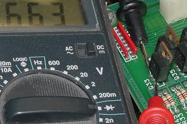
- Digital Multi-Meter (DMM).
- Logic Probe.
- Hand Crimping Tool: Molex WHT-1921 (part# 11-01-0015) or Molex part# 63811-1000. Contact extractor part# 11-03-0044 (about $20).
- Novus #2 or MillWax (for cleaning playfields and rubber)
- Novus #3 (for polishing metal parts)
- A paste wax (like Trewax) or hard automotive Carnauba Wax (for waxing playfields and cleaning rubber)
Non-Specialized Tools Required:
Specialized Tools Required:
These specialized electronics tools are needed.
Please see http://marvin3m.com/begin
for details on the basic electronics tools needed.
Cleaning "Tools" Required:
1c. Getting Started: Parts to Have On-Hand
-
When fixing electronic pinballs, I would highly recommend having some parts
on-hand to make things easier and cheaper. All these parts are
available from a pinball retailer.
Parts to have:
- Light Bulbs: Have the following arounds.
- #47 or #44: small 6.3 volt bulbs used for the general illumination and CPU controlled lamps. Use #47 bulbs as they consume less power and produce less heat than #44 bulbs. Seventy five is plenty to do most games.
- #67: large 13.5 volt bayonette bulb used for flashers. Note Gottlieb System3 games do NOT use #89 bulbs. #67 bulbs are 13.5v, 4 candlepower, .59amps, and have a life of 5000 hours. Compare this to the #89 which is 13 volts, 6cp, .58amps, and have a life of 750 hours. The flasher circuits in Gottlieb System3 games are designed for #67 bulbs, not #89. And in some cases, a #89 just won't work.
- #555: wedge style 6.3 volt bulb used for the backbox general illumination.
- #904: 14 volt wedge style flasher bulbs. This bulb was only used in Freddy, to my knowledge (#67 flash bulbs are the System3 norm). The 904 is a 4 candlepower version of the 906 (6 candlepower). In a pinch, the 906 bulb can be used instead of a 904. But don't use a #912 (12cp), as that bulb draws way too much current and is too bright.
- Fuses: have five of any needed value on hand at all times.
- 1/2 amp slo-blo (playfield mounted fuse)
- 1 amp slo-blo (playfield mounted fuse)
- 1.5 amp slo-blo (playfield mounted fuse)
- 2 amp slo-blo (playfield mounted fuse)
- 2.5 amp slo-blo (playfield mounted fuse and bottom panel F5 power supply)
- 3/8 amp slo-blo (bottom panel F3/F4, display fuse)
- 3 amp slo-blo (bottom panel F10/F11, auxiliary power supply)
- 5 amp slo-blo (bottom panel F2, primary power)
- 7.5 amp fast-blo (bottom panel F9, playfield general illumination)
- 8 amp slo-blo (bottom panel F1, line input power and F7 solenoids)
- 10 amp fast-blo (bottom panel F8, backbox general illumination)
- 10 amp slo-blo (bottom panel F6, CPU controlled lamps and switches)
- Transistors: keep a few of each of these around:
- 12N10L or IRL530 or 20N10L or 22NE10L or IRL540 (driver board and auxiliary driver board). The 20N10L or 22NE10L or IRL540 are the best replacements, as they have higher drain current capabilities. These are used for coils transistors. The "L" means it's a logic-level MosFet. These parts should *not* have a "F" anywhere in the part number.
- 12P06 or IRF9530 (driver board). Used for lamp matrix strobes. Yes this one does have the "F" (IRF) part number.
- Chips:
- 74HC273: used to drive the 12N10L MosFet transistors.
- 7406: used to drive the MosFet 12P06 transistors.
- 74HC164: used to drive the 7406 for the lamps.
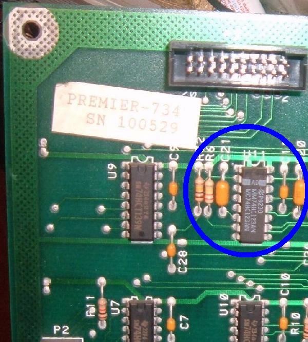
- 74HC123AN: used on the CPU board at U11. Note this chip *must* be this exact HC variety (the AN suffix is important too so it appears). It's a strange situation where if this chip is suspect, it can cause boot up problems (or issues when the game is warm.)
- 6264 RAM: main RAM at U3 for the CPU board. Note Cueball Wizard and prior System3 CPU games use a 6116 RAM (but these board can be re-socketed for a 6264). If replacing a 6116 RAM instead replace it with a 6264.
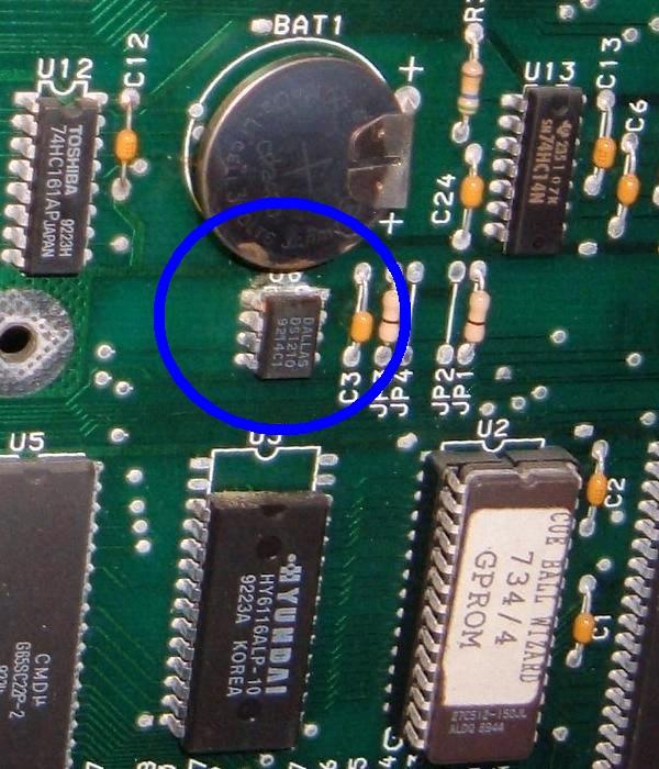
- Dallas DS1210 battery watchdog chip.
- LM339: voltage comparitor used heavily on the CPU board.
- 65C22 or 6522: PIA chip used on the CPU board. I've never seen one fail, but still not a bad idea to have around.
- 65C02: the CPU chip. Again never seen one fail but still worth having around.
- Chip Sockets or Machine Pin Strips: keep 8, 14, 16, 18 and 40 pin sockets around. Get good quality sockets! An even better (but more expensive) alternative is "machine pin strips". These come in a snapable length they can be custom made to any size socket needed. But the really good thing about them is they allow complete access to the socket area. These can be soldered into a board from the top and bottom.
- Misc. Parts
- 680 ohm 1/4 watt resistor for watchdog circuit R5/R6 (originally 330 ohms)
- 1 mfd electrolytic caps for the watdog circuit C20/C21
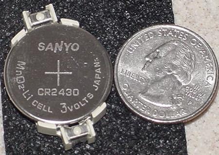
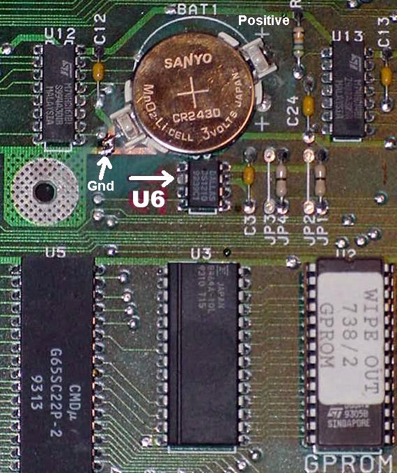
- CR2430 3.2 volt lithium battery, used on the CPU board (24mm x 3mm). Available from Mouser.com part# 639-cr2430. Alternatively BR2325/1HG. Also CR2032 (more common) can also be used.
- Solder-in 24mm socket for above CR2430 or CR2032 battery. Available from Mouser.com part# 614-hu2430-1.
- Diodes: keep a few 1N4004 and 1N4148 (1N914 or NTE519) diodes around.
- Connector pins and housings: used to repair connectors. Get the some .156" Molex crimp-on Trifurcon variety. Also some Molex "Mini-Fit Jr." 4.2mm (.165") terminal pins. Part numbers for Sockets (Female pins), wire size 18-24 Tin plated Berylium Copper #39-00-0060. Wire size 18-24 Tin plated Brass #39-00-0039. Part numbers for pins (male), wire size 18-24 Tin plated Berylium Copper #39-00-0062. Wire size 18-24 Tin plated Brass #39-00-0041. See the connector section for more details.
Transistors, diodes, bridge rectifiers and other electronic parts are available from many sources. Please check out the parts and repair sources web page for details.
1d. Getting Started: Game List
-
Here are the list of the Gottlieb System3 games. Release
date and production numbers are given.
For reference, Bone Busters was the last System80 game, and the
first game with the (horrible) "thin flippers".
- Lights.. Action.. Camera!, 12/89, #720, 1708 made, full size game.
- Silver Slugger, 4/90, #722, 2100 made. FIRST "street level" game.
- Vegas, 7/90, #723, 1500 made, "street level" game.
- Deadly Weapon, 9/90, #724, 803 made, "street level" game.
- Title Fight, 11/90, #726, 1000 made, "street level" game.
- Nudge-It, 12/90, #N102, 54 made, NOVELTY game.
- Bell Ringer, 1/91, #N103, 160 made, NOVELTY game.
- Car Hop 1/91, #725, 879 made, "street level" game.
- Hoops 2/91, #727, 879 made. LAST "street level" game.
- Cactus Jack, 4/91, #829, 1900 made, new sound board, full size game.
- Class of 1812, 7/91, #730, 1668 made.
- Amazon Hunt III, 9/91 (not marketed in the US), #684D, 200 made.
- Surf'n Safari 11/91, #731, 2006 made.
- Caribbean Cruise, #C102, 200 made, COCKTAIL.
- Operation Thunder, 4/92, #732, 2513 made.
- Super Mario Bros, 4/92, #733, 4200 made.
- Super Mario Bros: Mushroom World, 5/92, #N105, 450 made, NOVELTY game.
- Cue Ball Wizard, 10/92, #734, 5700 made. Last game to use the smaller 6116 RAM U3 chip.
- Street Fighter II, 3/93, #735, 5500 made. First game to use the larger 6264 RAM U3 chip.
- Tee'd Off, 5/93, #736, 3500 made.
- Gladiators, 9/93, #739, 1995 made.
- Wipe Out, 10/93, #738, 2150 made.
- World Challenge Soccer, #741, 1/94, 1470 made.
- Rescue 911, 3/94, #740, 4000 made.
- Freddy: a Nightmare on Elm Street, 10/94, #744, 2800 made.
- Shaq Attaq, 2/95, #743, 3380 made.
- Stargate, 3/95, #742, 3600 made.
- Big Hurt, 6/95, #745, 1985 made.
- Waterworld, 9/95, #746, 1500 made
- Strikes N Spares 10/95, #N111, 750 made, NOVELTY bowling game (pinball sized and utilized flippers), two dot matrix displays and two dot matrix controller boards.
- Mario Andretti, 12/95, #747, 1120 made.
- Barb Wire, 4/96, #748, 1000 made.
- Brooks & Dunn, 8/96, #750, 1 made.
- Casino Royale, 8/96, #751, 0 made (game never produced).
Alpha-Numeric with two 20-digit (with commas) blue Futaba displays:
Dot Matrix, 132x32 standard dot matrix display:
Legs
Gottlieb was fairly inconsistent about leg lengths used.
Basically with the game set up, the top of the lockdown bar
should be about 35" tall. To get this proper height,
27" legs were correct on games Tee'd Off and prior. But
starting with Wipeout (except Big Hurt which appears to use 27" legs),
Gottlieb used 31" legs.
Another way to tell if 31" legs are proper is to look
at the top of the leg, and compare it to the location
of the start button. If the top of the leg (as installed on the game)
is nearly to the bottom of the start button, this game uses 31" legs.
If the top of the leg is lower than the start button, then 27" legs are correct.
Other Notes:
"Street level" games was an experiment by Gottlieb at simplier,
single level, no ramp, slightly smaller and slightly cheaper
games. They made six street level games: Silver Slugger, Vegas,
Deadly Weapon, Title Fight, Car Hop and Hoops. This experiment
failed BADLY. At the time, these games were selling against the
likes of Williams Whirlwind (Williams sold more Whirlwinds than
all six Gottlieb street level games combined!) Obviously Gottlieb
got their butt kicked by Williams, hence with Cactus Jack, Gottlieb
system3 returned to a 'normal' sized game with all the bells
and whistles! (Cactus Jack is actually a good game too.)
Frank Thomas, who's likeness was portrayed on "Big Hurt", was listed as a Gottlieb creditor when Gottlieb went out of business. Apparently Frank never got paid. Shaq on the other hand DID get paid for his game, and was not listed as a creditor!
1e. Getting Started: Gottlib System3 Overview video
This 12 minute movie explains the Gottlieb System3 solid state pinball system and it's electronic parts, along with what Gottlieb did differently than Williams/Bally and Dataeast.
1f. Getting Started: The Circuit Boards
-
Here are the boards that live in the backbox (head) of the electronic
Gottlieb System 3 pinball games.
- A1 = CPU (Control) board
- A2 = Power Supply board (5 volts only)
- A3 = Driver board
- A4 = Dot Matrix Display (DMD)
- A5 = Aux Power Supply board (-12, +12 volts for sound board)
- A6 = Sound board
- A20 = Aux Sound board
- A8 = Dot Matrix or Alpha-Numeric Controller board
- A11 = Auxiliary Driver board (not used on all games)
- A12 = Transformer panel (bottom cabinet)
- A13 = PF Resistor board
- A15 = Sensor board for flippers
- A16 = Filter board
- A17 = Diode board
- A18 = Ground board bolted to the A12 transformer frame
- A25 = Opto Interface board (not used on all games)
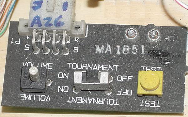
- A26 = Game Controls board (test, tournament, volume control)
- A27 = Communications Adaptor (optional)
- 0 = Black
- 1 = Brown
- 2 = Red
- 3 = Orange
- 4 = Yellow
- 5 = Green
- 6 = Blue
- 7 = Violet
- 8 = Gray
- 9 = White
Board A-numbers.
Wire Color.
|
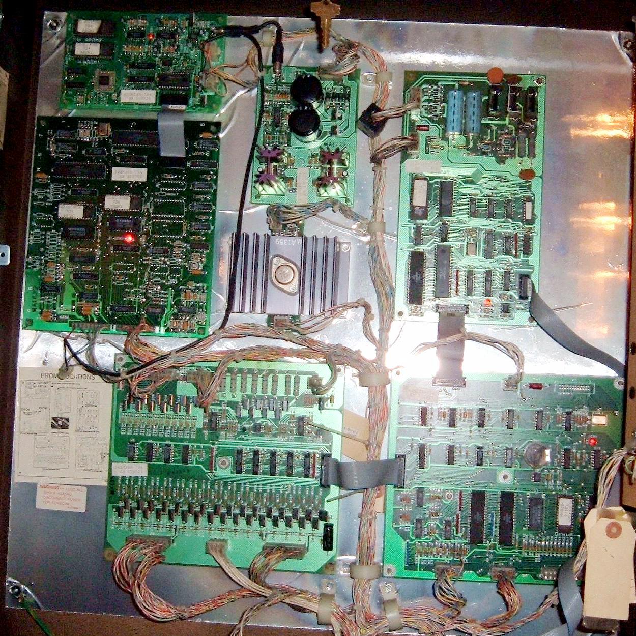
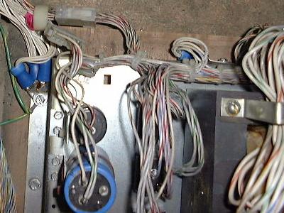
The backbox in a Wipeout showing all the circuit boards. |
|
|
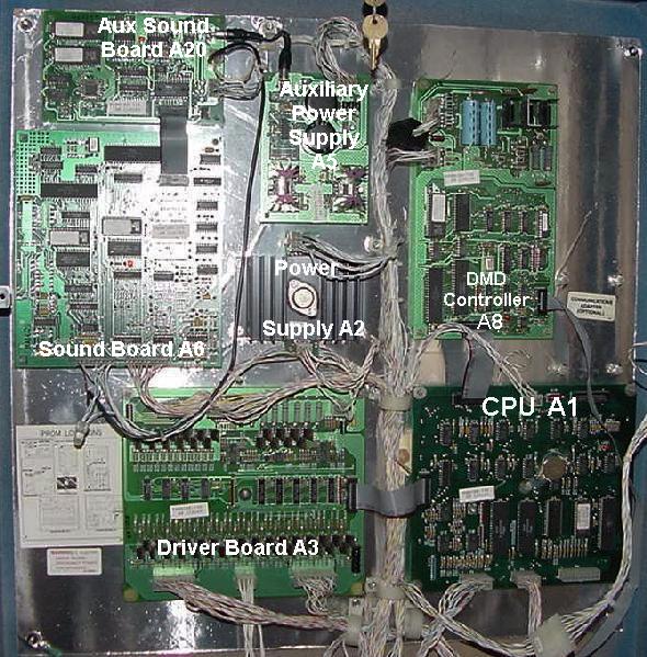
The backbox in a Cueball Wizard showing all the circuit boards. |
|
-
A1 CPU Board.
- JP1=in, JP2=out: 27512 EPROM at U2
- JP1=out, JP2=in: 27256 EPROM at U2
- JP3=in, JP4=out: 6116 RAM at U3
- JP3=out, JP4=in: 6264 RAM at U3
- P1 = +5 volts DC power
- P2 = Ribbon cable to driver board
- P3 = Ribbon cable to dot matrix controller board or alpha-numeric display board
- P4 = Sound board connector (sound board's LED won't flash if this is not connected).
- P5 = Switch matrix returns (including slam, tilt and test switch returns).
- P6 = Auxiliary Driver board (only used on some games)
- P7 = Communications adaptor (optional)
Though most System3 CPU boards are compatible from game to game, be aware that System3 CPU boards Cue Ball Wizard (game# 734) and earlier used a 6116 RAM at U3 (24 pins), and later CPU boards used a 6264 at U3 (28 pins). The newer 26285-1 CPU board increased SRAM from 2k to 8k bytes, and changed the timing logic from the earlier 26285 board. Street Fighter 2 (game# 735) was the first game to use the new 26285-1 CPU board with increased RAM space.
If a game is expecting a 26285-1 revision CPU board with a 6264 at U3, and an earlier CPU board with a 6116 RAM is installed, strange problems will occur. For example, the game is "stuck" showing the last four high scores and won't progress any further into attract mode. Also the game won't be able to enter test mode and will not coin up. The easiest way to tell which RAM is installed is to just count the number of pins for chip U3 (24 pins=6116, 28 pins=6264). There is also a pair of jumpers that determines which size RAM is used, and a pair which determines which size EPROM is used:
The CPU board uses a 65C02 processor with a 2mHz clock supplied to U18 to pin 39 and pin 37 of the 65C02 at U1 (crystal at 4mHz). VIA (versatile interface adaptors) 6522AP chips at U4 and U5 are used on the CPU board. The only voltage needed to boot the CPU board is +5 volts DC at connector P1. Here are the connectors used on the CPU board:
Some CPU boards do not have a 24 pin ribbon cable receiver connector installed at P7. This connector is used for a communications adaptor A27, so it is not necessary to run the game. Another connector usually not used on the CPU board is P6, which is for an auxiliary driver board A11. Note the CPU board gets the switch matrix returns, and the driver board gets the switch matrix strobes.
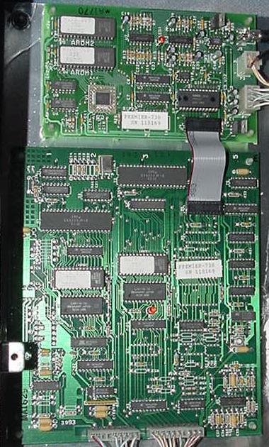
|
The CPU board (A1). |
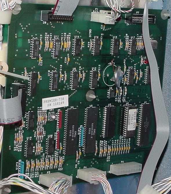
|
-
One chip that is critical to the timing of the CPU board is at U11.
This chip must be a 74HC123AN or the game will not boot (or will constantly
reboot). U11 must be this exact HC variety (a 74LS123 will not work).
A3 Driver Board.
The driver board controls the lamp strobe/return signals,
switch matrix strobe signals, and the solenoids.
MosFET 12N10L or IRL530 logic level transistors are used to control the 32 solenoids
through 74HC273 chips. Really there are only 29 solenoids available for the
game though, as two MosFETs (Sol.31 and Sol.32) are used to control
the Game-Over and Tilt relays in the lower cabinet, and most games also use
one MosFET for controlling the backbox illumination.
Some games use an Auxiliary Driver board with an additional
eight 12N10L or IRL530 MosFETs and a single 74JC273 chip (if the game is complicated
enough to need more than 29 CPU controlled solenoids or flash lamps - this Auxiliary Driver
board is connected directly to the CPU board). The Auxiliary Driver board is almost
always used just for flash lamps.
|
The driver board (A3). |
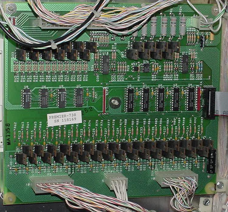
|
-
The matrix strobe lines use 12P06 (through 74HC164 and 7406 chips)
for the lamp and switch strobes, and 12N10L MosFETs (through 74HC273 chips)
for the lamp returns. There are twelve lamp/switch strobes and eight
returns, for a total of 96 CPU controlled lamps and 96 switches.
The lamp and switch matrix share the same twelve strobe lines interestingly.
Yet each have eight separate discrete return lines.
|
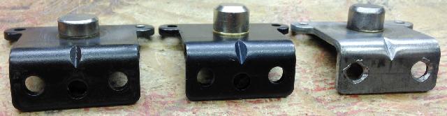
The bottom cabinet A (backbox GI), T (tilt) and Q (Game Over) relays. |
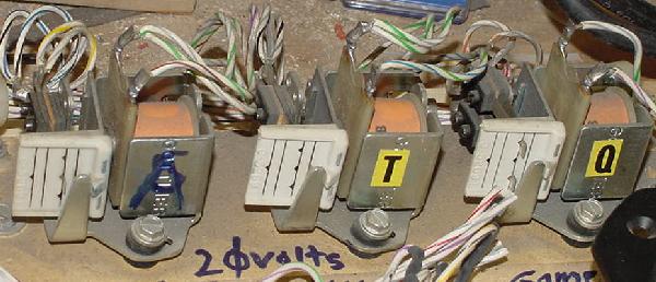
|
-
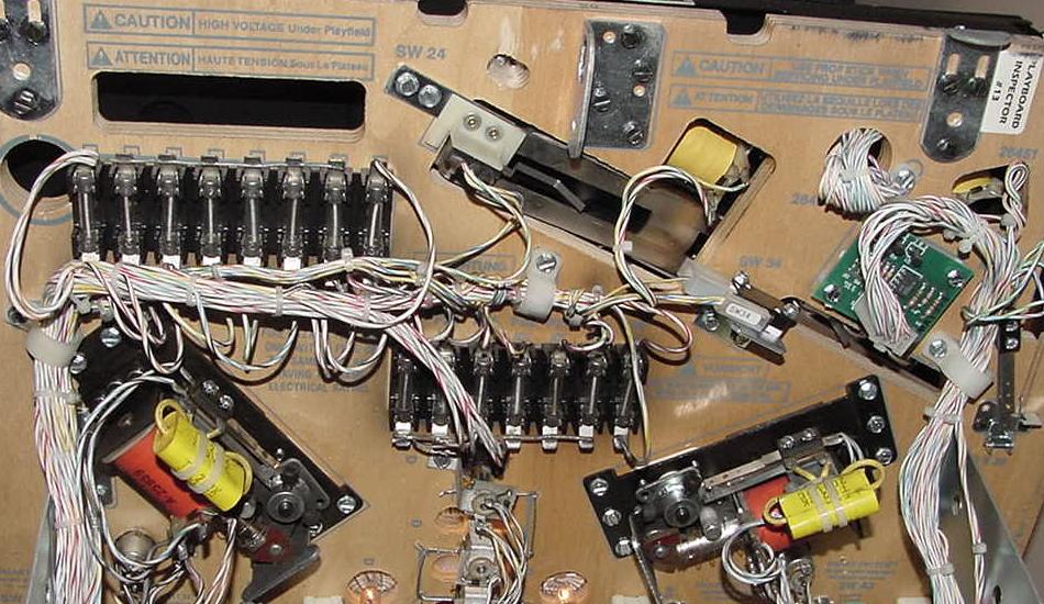
Bottom Cabinet Relays.
- "Q" Game over relay - two Normally Open (NO) switches that close when the relay is energized. The game over relay stays energized during the entire game and turns on the power to the Flippers (only) through these two switches. This is all the Game Over relay does. Williams and Bally essentially have the same thing but they call it the "flipper relay" (and it's mounted on the driver board). Gottlieb felt the Game Over (aka Flipper relay) should be mounted in the lower cabinet. Controlled by driver board MosFET Q32 (aka Sol.31).
- "T" Tilt relay - one Normally Closed (NC) switch that opens when the relay is energized when the player tilts. When the game tilts during play, this one switch on the Tilt relay opens, turning off the General Illumination to the playfield. Controlled by driver board MosFET Q31 (aka Sol.30).
- "A" Insert Illumination relay (used on most games). This relay is much like the Tilt relay with a single normally closed switch, but instead controls the backbox General Illumination. When the A relay is energized, it turns off the backbox General Illumination. This is used during game play for dramatic emphasis. Controlled by driver board MosFET Q26 (aka Sol.25).
Gottlieb still used relays in the bottom panel of their system 3 games. All relays used in System3 games are powered by 20 volts (not 50 volts like the other coils). All games have at least two relays controlled by MosFETs Q30 and Q31 on the Driver board, and nearly all have three relays. Sol.31 (Q32) controls the Game Over relay, and Sol.30 (Q31) controls the Tilt relay. Nearly all the games also have an "A" relay which toggles the General Illumination in the backbox. This is controlled by Sol.25 (Q26).
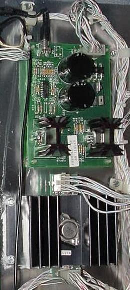
|
The bottom panel of a Wipeout. The three relays can be seen at the right. |
|
-
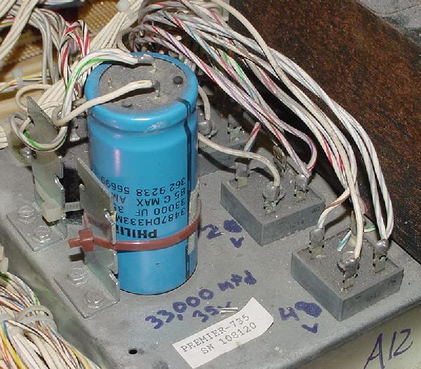
A12 Transformer Panel.
- 12 volts DC through a 10,000 mfd filter capacitor. The 12 volt power ultimately turns into regulated +5 volts, which feeds to all the circuit boards. The 12 volts is also used for other things like opto switches, etc.
- 20 volts DC through a 33,000 mfd filter capacitor. For the flash lamps, relays, lamp matrix, and DMD controller board.
- 48 volts DC (no filter cap) for the solenoids.
- 95 volts AC for the dot matrix controller.
- 58 volts AC for the dot matrix controller.
- 12.6 volts AC for the Auxiliary power supply board (which provides +12 and -12 volts DC to the sound board).
- 6.3 volts AC (for the general illumination).
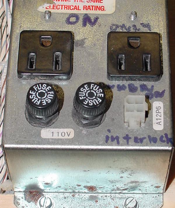
Power is supplied from the transformer panel in the lower cabinet. The wall voltage is selected using Gottlieb-supplied jumper plugs. The jumper plug for 120 volts is ORANGE. This is the plug that should be installed in all North American games. If a 110 volt RED jumper plug is installed, replace it with the orange 120 volt plug.
There are three bridge rectifiers which supply:
In addition the transformer supplies the following AC voltage (higher voltages listed are for dot matrix games):
Gottlieb system 3 games came from the factory jumpered for 110 volts. But they also had a transformer plug that allowed for 120 volt operation. This change should always be made to jumper the game for 120 volts. This keeps the unregulated voltage (such as the General Illumination) lower, for increased bulb life. The regulated voltages (such as 5 volts) should be the same in either jumper setting.
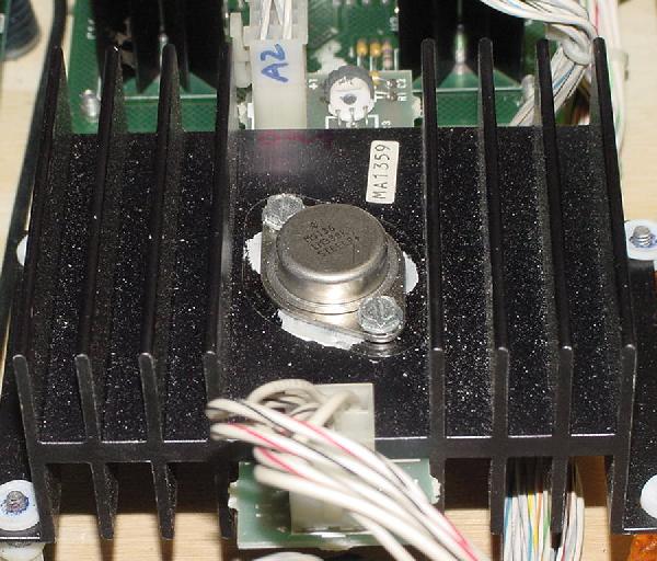
A2 Power Supply and A5 Auxiliary Power Supply.
The power supply A2 is a simple design. It takes raw 12 volts DC from
the bottom panel bridge rectifier and a 10,000 mfd filter cap, and outputs
+5 volts DC regulated. This is adjustable via a 500 ohm trim pot at R3.
A voltage regulator LM338 (the large heat sink device) is the 5 volt workhorse.
Also unregulated 12 volts DC is "turned around" at the power supply,
but there is no circuit control mechanisms for this voltage.
Gottlieb system3 +5 volt DC power supplies did not have an "over voltage" protection circuit. Most power supplies have a 6 volt zener diode, which would automatically shut down the 5 volt power supply if the supplying voltage regulator shorted (and sent more than 6 volts down the 5 volt power rail). But Gottlieb did not do this. Hence if the 5 volt regulator on the power supply shorts (or the 500 ohm pot fails), it can ruin LOTS of chips in the process!
The auxiliary power supply A5 is a bit more complicated, and takes 12.6 volts AC directly from the transformer and converts it to +12 and -12 volts DC for the sound board using a LM7912. It also produces +5 volts using a LM340T (7805). This goes thru an op-amp MC3403 (or LM324AN or NTE987). The auxiliary power supply also uses two TDA2040 amplifier chips for the sound amplification (note TDA2030 chips can be used, but don't output as much power).
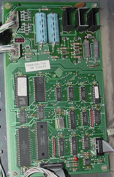
|
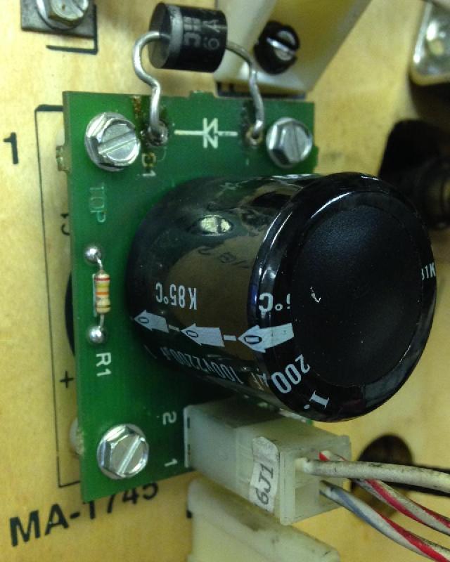
The auxiliary power supply (A5, top) and power supply (A2, bottom). |
|
|
The A2 power supply. The 500 ohm +5 volt adjustment trim pot can be seen at the top. |
|
-
A6 Sound board and A20 Auxiliary Sound board.
The A6 sound board has two 65C02 processors, a dual DAC (digital to analog converter), and an import port to receive signals from the CPU board. The sound board requires +5, +12 and -12 volts DC and a power-up reset signal from the CPU board (pressing sound board SW2 will give a manual reset). There are two 27256 EPROMs (the D1 and Y1 PROMs as Gottlieb calls them). This board is responsible for all the music and non-voice sounds.
The Auxiliary sound board A20 is the smaller of the two sounds board, and has a YM2151 sound generator and a MSM6295 sound/speech generator. This board gets commands from the CPUs on the A6 sound board. This board has two 27020 or 27040 EPROMs (the A1 and A2 PROMs as Gottlieb calls them). This board is responsible for all the voice tracks. The game will work without this board, but of course there will be no speech.
|
The auxiliary sound board (A20, top) and sound board (A6, bottom). |
|
|
The auxiliary sound board A20. |

|
-
A8 Dot Matrix Controller Board.
- +62 volts DC
- +12 volts DC
- -100 volts DC
- -112 volts DC
- +5 volts DC
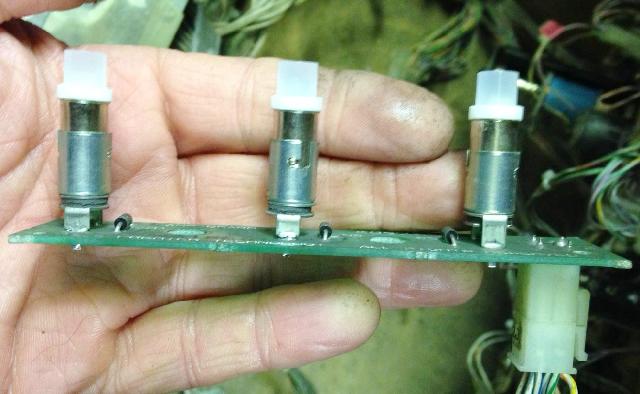
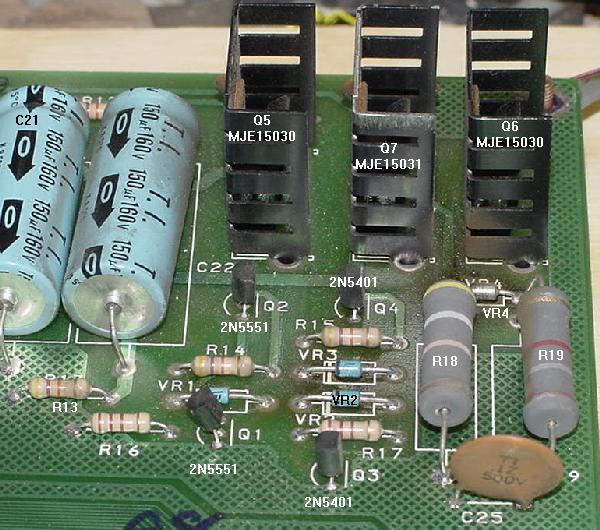
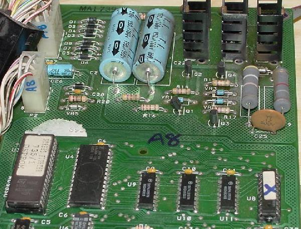
The dot matrix controller board has its own 65C02 processor and its own EPROM to do the dot matrix animations. The controller talks to the CPU board through a ribbon cable. The dot matrix controller board takes in 58 volts AC and 95 volts AC through two bridge rectifiers on the DMD controller board. This goes through two MJE15030 and a MJE15031 and 1N4759, 1N4758 and 1N4742 diodes and 2N5551 and 2N5401 transistors. Also +5 and +20 volts DC comes into the board. This is a very similar circuit design to what Williams uses on their DMD controller. Output voltage are:
|
The dot matrix controller board (A8). |
|
Alpha-Numeric Score Displays.
Games before Super Mario Brothers used Alpha-Numeric score displays,
and did not have a dot matrix controller board.
All Gottlieb alpha-numeric solid state games used
blue "Futaba" brand score displays. These were florescent
blue displays, and effectively never wore out, because
the display voltage was much lower (60 volts) than the gas discharged
displays used by Williams and Bally (+/-100 volts).
|
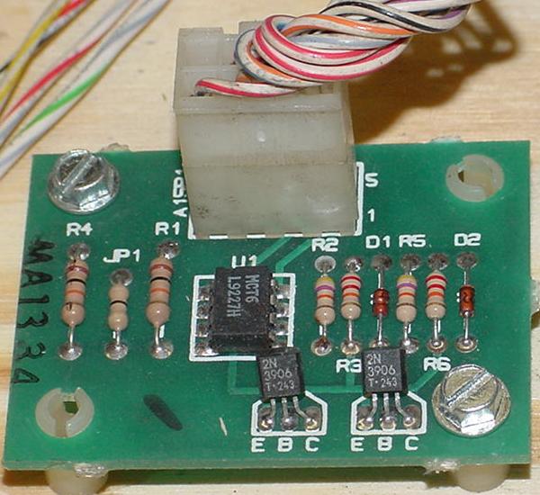
System3 flipper Sensor board (A15). |
|
-
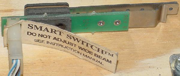
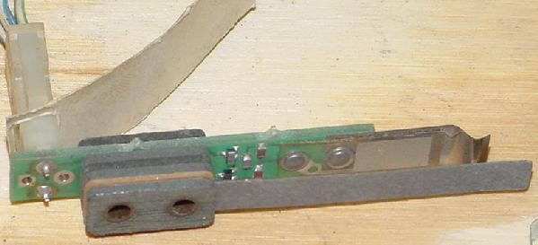
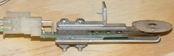
A15 Flipper Sensor board.
Mounted under the playfield, a small board is used to sense when the flipper buttons are pressed. The voltage stream is seen by this board, and is converted thru an opto isolator and two 2n3906 transistors. This tells the CPU's switch matrix that the left or right flipper buttons have been pressed.
|
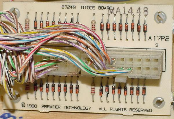
The A17 diode board mounted under the playfield for the switches. |
|
-
A17 Diode board.
Gottlieb took a different approach to playfield switch diodes than Bally or Williams. Instead of mounting the playfield switch diodes right on the switch, they preferred to mount them on a separate board. This board was mounted under the playfield, usually near the outhole. Having the diodes on this board meant changing a switch was rather mindless; there's not special wiring (or even a diode) needed to install a new switch, and no wires to mix up. Also cracked diodes from vibration are much rarer when the diodes are separated from the switch. The downside of this approach was if there was a switch diode problem, the user would have to figure out which diode on the switch board applied to the switch in question.
|
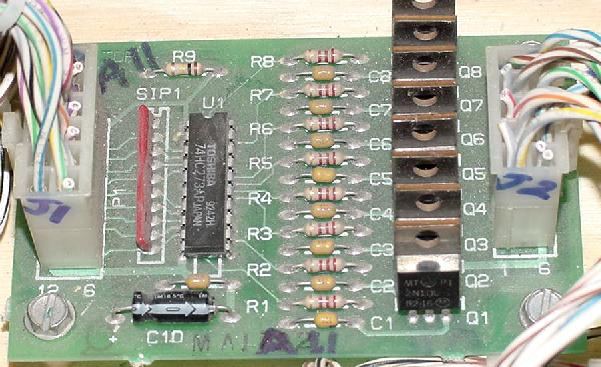
System3 Auxiliary Driver board (A11). |
|
-
A11 Auxiliary Driver board.
Some games needed additional MosFET driving transistors because the 32 available on the driver board for coils and flash lamps just were not enough. This is done through a small Auxiliary Driver board, which has eight additional 12N10L MosFETs. This board connects directly to the CPU board, and is generally used just to power flash lamps. Not all System3 games use this board.
|
System3 block diagram for an Alpha-Numeric game (Surfin Safari). |
|
|
System3 block diagram for a Dot Matrix game (Stargate). |
|
-
Slam Switch.
As with Gottlieb System1 and System80, System3 has a coin door mounted Slam switch. But unlike the earlier systems, the Slam switch is now Normally Open. That means the switch must close to register a "slam" (ending the player's game). This is a much better idea than the System1 and System80 normally closed slam switches.
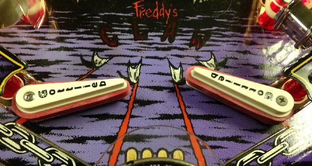
System3 Flippers.
All system3 games used the new Gottlieb "thin flippers" instead
of the long proved "fat boy" flippers. This was a down-grade
in Gottlieb's flipper design, as the thin flippers were built with cheaper
parts, and had a cheaper feel.
1g. Getting Started: Connnector Backbox List & Usage
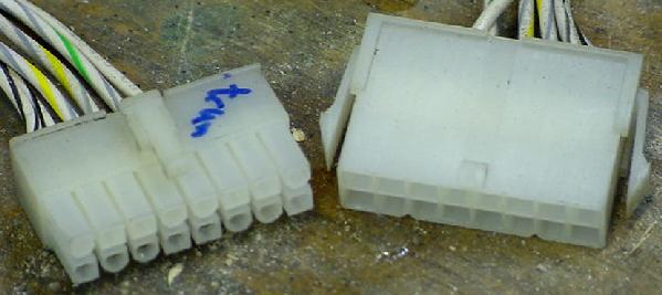
Gottlieb solidstate games have had a history of problems. System1 and System80 used primarily card-edge style connectors (combined with battery leakage) that causes all sorts of reliability problems. Fortunately with Gottlieb System3, connector problems are largely a thing of the past. Gottlieb used a new style of connector that has excellent reliability. This is called the Molex "Mini-Fit Jr." 4.2mm (.165") series of connectors. Part numbers for Sockets (Female pins), wire size 18-24 Tin plated Berylium Copper #39-00-0060. Wire size 18-24 Tin plated Brass #39-00-0039. Part numbers for pins (male), wire size 18-24 Tin plated Berylium Copper #39-00-0062. Wire size 18-24 Tin plated Brass #39-00-0041. About the worst I can say about the System3 connectors is their lack of individuality (it's easy to mis-connect them, because they are not keyed very well).
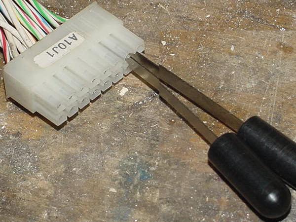
Pin removal of these square-pinned connectors is different than other pinball style connectors. There is a specialized tool for this job, contact extractor part# 11-03-0044 (about $20). But I ended up using two Molex card edge pin extraction tool part# 11-03-0016 to remove the square female pins from the connector housing. I'm sure this isn't the best method, but it did work without damaging the terminal pin.
|
The System3 connector style. |
|
|
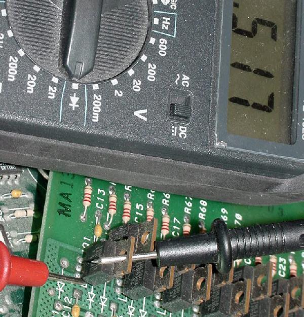
Using two Molex 11-03-0016 pin removal tools to extract the female pin from the housing. |
|
|
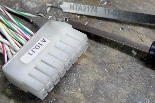
The square extracted terminal pin and housing, and the two extraction tools. |
|
-
Backbox Connector Confusion.
- A1J1 pin 1=Blue, Gray, Gray. Pin 2=Blue, gray, gray. +5 volt power.
- A1J4 pin 1=Violet, Violet, Orange. Pin 2=Orange, blue, blue. Sound interface.
- A1J5 pin 1=Blue, Violet, Violet (often this wire is missing). Pin 2=blue, blue, blue. Switch matrix return.
- A2J1 pin 1=red, black, black. Pin 2=white. Raw power in.
- A2J2 pin 1=blue, gray, gray. Pin 2=blue, gray, gray. Regulated +5 volt power out.
- A3J1 pin 1=white. Pin 2=blue, gray, gray. Power in.
- A3J3 pin 1=violet, orange, orange. Pin 2=violet, red, red. Lamp/Switch matrix strobe.
- A3J4 pin 1=grey, black, black. Pin 2=gray, brown, brown. Lamp matrix return.
- A3J5 pin 1=red, black, black. Pin 2=red, brown, brown. Solenoids 0-15.
- A3J6 pin 1=green, black, black. Pin 2=green, brown, brown. Solenods 16-31.
- A3J7 pin 1=white. Pin 2=white. Lamp matrix and solenoid ground.
- A5J1 pin 1=Brown, Brown, Black. Pin 2=white, blue, blue.
- A6J1 10 pin .156" inline Molex, key = pin 4.
- A6J2 9 pin .156" inline Molex, key = pin 7.
- A8J1 pin 1=Brown, Red, Red. Pin 2=brown, yellow, yellow. Power in; has ceramic noise filter.
- A8J2 pin 1=Blue, Gray, Gray. Pin 2=white, gray, gray. Power out to score display.
- A20J3 pin 1=red shielded wire. Pin 2=white, yellow, yellow.
- A20J1 pin 1=blue, gray, gray. Pin 2=green, green, brown.
- 12 volts = red black black
- Speaker = black red red
One really nasty problem with Gottlieb System3 games are the backbox connectors. If for some reason someone has removed all the connectors from the circuit boards (for moving the game, etc), it can be an absolute hair puller putting the connectors back where they belong! The problem is many of these connectors are the same exact size and have no "key". So one connector can often plug into two adjacent connectors. Because of this, below are the easily confused connectors for each board *including* wire color. Wire color is the only way to tell one connector from another of the same size.
Speaking of wire color, each wire has a white base color with *three* colored stripes. Gottlieb was the only pinball manufacturer to color wires in this manner. In fact Gottlieb had their own machine which fed white wire and put the colors stripes on the wire. All the other manufacturers bought their wire pre-colored. The Gottlieb wire coloring does take a bit of getting used to.
WARNING: IF THE BACKBOX CONNECTORS ARE ATTACHED INCORRECTLY, DAMAGE WILL OCCUR TO THE CIRCUIT BOARDS.
ALSO DO NOT REMOVE ANY CONNECTORS THAT ATTACH TO THE A8 DOT MATRIX DISPLAY BOARD WHILE THE POWER IS ON (INCLUDING THE DOT MATRIX DISPLAY ITSELF).
Failure to heed the above advice will do damage to a Gottlieb System3 boardset.
A1 CPU Control Board Connectors.
A2 Power Supply Connectors.
A3 Driver Board Connectors.
A5 Aux Power Supply Connectors.
A6 Sound Board Connectors.
A8 Dot Matrix Controller Board Connectors.
A20 Aux Sound Board Connectors.
Note some backbox wiring have a 2 prong connector that connects to raw 12 volts (as fed to the A2 power supply). This just happens to be the same style connector that is used for the speakers. If this is accidently connected to a speaker connector, it will smoke the TDA2040 (or TDA2030) amplifier chips on the A5 Auxiliary Power Supply, the LM340T (or 7805) 5 volt 1 amp voltage regulator, and the MC3403 (or LM324AN) op-amp chip. To make things worse, the wire colors for the speakers and the 12 volts are very similar:
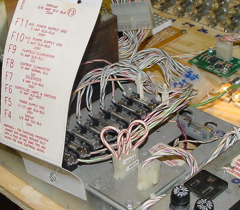
1h. Getting Started: Fuse Values/Usage
- F1: 8 amp slo-blo (line input power)
- F2: 5 amp slo-blo (primary power)
- F3: 3/8 amp slo-blo (95 volt AC DMD display power fuse) - vertical style fuse holder (often fails)
- F4: 3/8 amp slo-blo (58 volt AC DMD display power fuse)
- F5: 2.5 amp slo-blo (10 volt AC power supply). Goes to the 12 volt DC bridge rectifier.
- F6: 10 amp slo-blo (16 volt AC for the CPU controlled lamps and switches). Goes to the 20 volt DC bridge rectifier.
- F7: 8 amp slo-blo (50 volt AC solenoids). Goes to the 48 volt DC bridge rectifier.
- F8: 10 amp fast-blo (6.3 volt AC backbox general illumination)
- F9: 7.5 amp fast-blo (6.3 volt AC playfield general illumination)
- F10: 3 amp slo-blo (12.6 volt AC auxiliary power supply)
- F11: 3 amp slo-blo (12.6 volt AC auxiliary power supply)
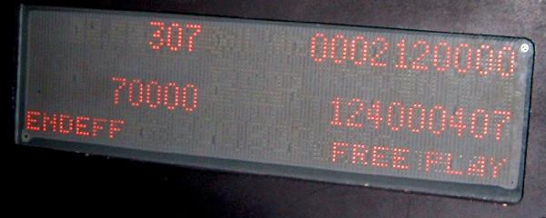
First note is if the game powers up, display shows the software revision, then gives a ball missing warning, then shows zeros and 'game over' in the display, then is completely dead. No lamps, no display messages, no switch inputs have any affect (like the test switch). All the LEDs on the boards are flashing as they should be. Excellent chance the entire problem is the CPU controlled light fuse, which also powers the switch matrix too. If this fuse blows, and blows right away once you install new fuse, then the bridge rectifier connected to that fuse is shorted.
Power Box Fuses (has two AC plugs):
A12 Transformer Module Fuses:
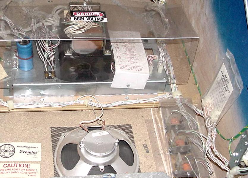
|
The bottom panel of a Wipeout. |
|
|
|
The A12 transformer panel fuses. Note the vertical F3 fuse holder has been replaced with a (gray) flat style fuse holder. |
|
-
Playfield Mounted Fuses.
- 1/2 amp slo-blo
- 1 amp slo-blo
- 1.5 amp slo-blo
- 2 amp slo-blo
- 2.5 amp slo-blo
The playfield fuses vary from game to game. But here are the values generally used under the playfield.
|
The under playfield fuses. On the right is the A15 Sensor board, which tells the CPU board if the cabinet flipper buttons have been pressed. A optocoupler is used for this. |
|
1i. Getting Started: System3 Ground Issues & Fixes
In the tradition of all Gottlieb solidstate games, System3 has ground problems too (not unlike Gottlieb's System1 and System80 pinballs). Gottlieb never seemed to get grounding issues solved with any of their solidstate systems. The big problem with Gottlieb was their refusal to use a metal ground plate to attach all their circuit boards (like Williams and Bally and Stern used). Instead they insisted on using nylon circuit board attachment points and used connectors to carry the ground path. The problem with this is connectors can gain resistance, making ground levels "float" above zero volts. This can cause all sorts of problems.
In the case of Gottlieb System3, all the grounds meet at the A18 transformer ground assembly. There is a small circuit board attached to the side of the A12 metal transformer frame which connects all grounds together. The problem is these connectors can crack at the solder point on the A18 ground board. This of course means the ground path is not reliable and can "float".
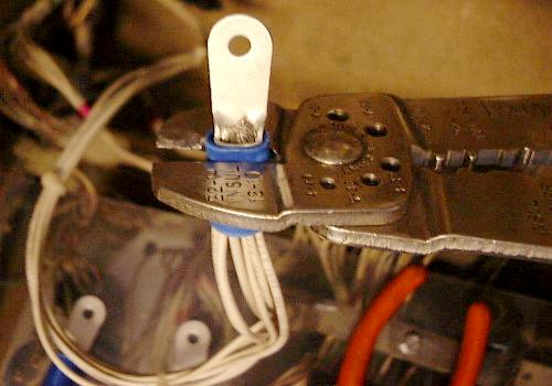
There are two solutions to this problem. The one John Robertson likes is to cut off the factory ground connectors which mate to the A18 ground circuit board. Instead he crimps large connectors to these wires and bolts them directly to the A12 transformer frame. Personally I am not a huge fan of this method. I take a slightly different approach.
|
The John Robertson System3 ground fix approach using crimped connectors bolted directly to the A12 transformer frame. These four A18 transformer connectors are cut-off and replaced with crimped bolt-on connectors. |
|
|
The crimped connector mating all wires together. |
|
|
The crimped connectors bolted directly to the A12 transformer frame. |
|
-
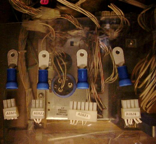
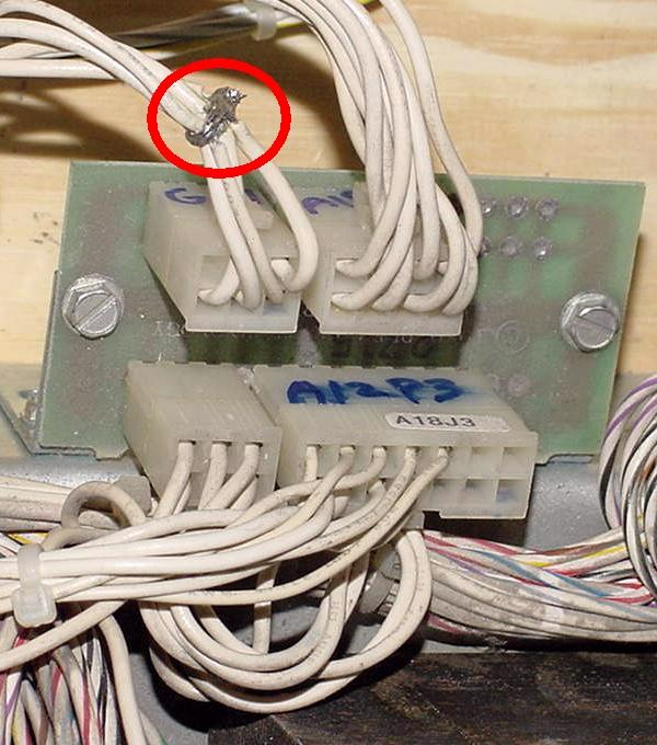
My approach maintains the original A18/A12 ground connectors. But instead
I tie all the ground wires for one connector together. This way if
one pin (or more) in the connector fails, it really does not matter,
because all the wires are tied together. As long as at least one pin
in the connector is still good, an excellent ground connection is maintained.
This needs to be done for all four ground connectors that attach to the A18 ground
board bolted to the side of the A12 transformer frame. This could
be taken even one step further, and tie all four connector wire bundles
together (though I personally don't go that far).
|
My approach to fixing the System3 ground problem. This is the ground board A18 that is bolted to the side of the A12 transformer frame. As seen on the connector at the upper left, all the ground wires for this ground connector are tied together and soldered. If one or more connector pins fail, the other good pin(s) will carry the ground to the transformer frame. |
|
1j. Getting Started: LED Flash Codes for the Circuit Boards
- A8J1 pin 9 = +5 volts DC
- A8J1 pin 5 = 20 volts DC
- A8J1 pin 10 = ground
- A8J1 pin 1 = 58 volts AC
- A8J1 pin 2 = 58 volts AC return
- A8J1 pin 3 = 95 volts AC
- A8J1 pin 4 = 95 volts AC return
- A8J2 pin 1 to DMD pin 6 (+5 volts)
- A8J2 pin 2,3 to DMD pin 4,5 (ground)
- A8J2 pin 4 to DMD pin 7 (+12 volts)
- A8J2 pin 5 to DMD pin 8 (+62 volts)
- A8J2 pin 7 to DMD pin 1 (-112 volts)
- A8J2 pin 8 to DMD pin 2 (-100 volts)
Most boards in the backbox of a Gottlieb System3 game have a diagnostic LED. If a system3 game boots correctly, here is what each board's LED does.
A1 CPU Control Board LED.
The CPU board's single LED will flash continually and evenly if the board
boots correctly. If the CPU board's LED flashes very fast for a second,
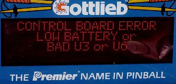
then pauses just a moment, then repeats, this usually indicates a low CPU board
battery or a bad U11 chip.
A8 Dot Matrix Controller Board LED.
The DMD (Dot Matrix Display) Controller board's LED should also
flash continually and evenly (but not quite as fast as the CPU board's LED).
If the DMD Controller board's LED is
stuck on, this usually means there is a problem with the
custom GAL (Generic Array Logic) chip at U8. The GAL is a programmable
chip that replaces several 7400 series TTL logic chips.
A bad U8 GAL chip will also cause
the DMD to show "garbage". This chip is available from a number
of sources (but must be programmed).
A6 Sound Board and A20 Auxiliary Sound Board LEDs.
Each of these two sound boards have an LED. Both boards' LED should
be flashing continually when the game is powered on. If neither
LED is flashing (off), usually this means the
sound board to CPU board connector at CPU board P4 is disconnected.
Or there is no +12/-12 power coming from the Auxiliary Power Supply.
A3 Driver Board, A1 Power Supply, A5 Auxuliary Power Supply.
These three boards do not have any LEDs. But if the A1 power supply
is not working, none of the other boards will boot. If the A5 Auxiliary
Power Supply is not working, the two sound board LEDs won't light either.
Sound Board Dual "Screech" Sound at Boot-Up.
One thing common to all System3 games is the bootup two tone
"Screech" sound. If the Auxiliary power supply is working,
fuses F10/F11 are good, the speakers are connected,
and the Sound boards boot-up properly, the game will make
two quick and obnoxious high pitched squeels as soon as the
power is applied. This is a normal behavior and signifies
the sound boards are working.
Booting a CPU board "On the Bench".
The CPU board can be booted without the rest of the game
using just an external 5 volt power supply. Just connect
the CPU board's A1P1 connector to a computer switching power supply and
power up (A1P1 pin 1=+5 volts, A1P1 pin 4=ground).
If the CPU board LED flashes, the CPU board has booted.
Though pretty useless just like this, it will give you
some idea if a Gottlieb System 3 CPU board is dead or not.
If you would like to get fancy, the next board needed is the dot matrix controller board. With this board connected to the CPU board via a ribbon cable at A1P3 to A8P3, the dot matrix controller board can be booted too with these input power sources:
U8 DMD Controller GAL Chip.
On the dot matrix controller board there is a custom
programmed GAL chip at U8. This is a common failure
point for the DMD controller board. If the game turns
on and has garbage on the DMD, often the U8 GAL chip
is bad. Also if the DMD controller board LED stays
on and does not flash continually, this is another
indicaton the U8 GAL chip is bad. The CPU board "talks"
to the Dot Matrix Controller board, and if this
U8 GAL switch is bad, the CPU board will not boot-up
correctly.
The GAL U8 chip fails for one primary reason; If any plug going to the Dot Matrix Controller board is removed or installed while the game is powered on, the U8 GAL chip can fail. This means plugging in the dot matrix score display while the game is on can make the U8 GAL fail.
Fortunately the U8 GAL chip is available from a variety of sources such as Pinball Resource and Great Plains Electronics. The chip is not cheap though.
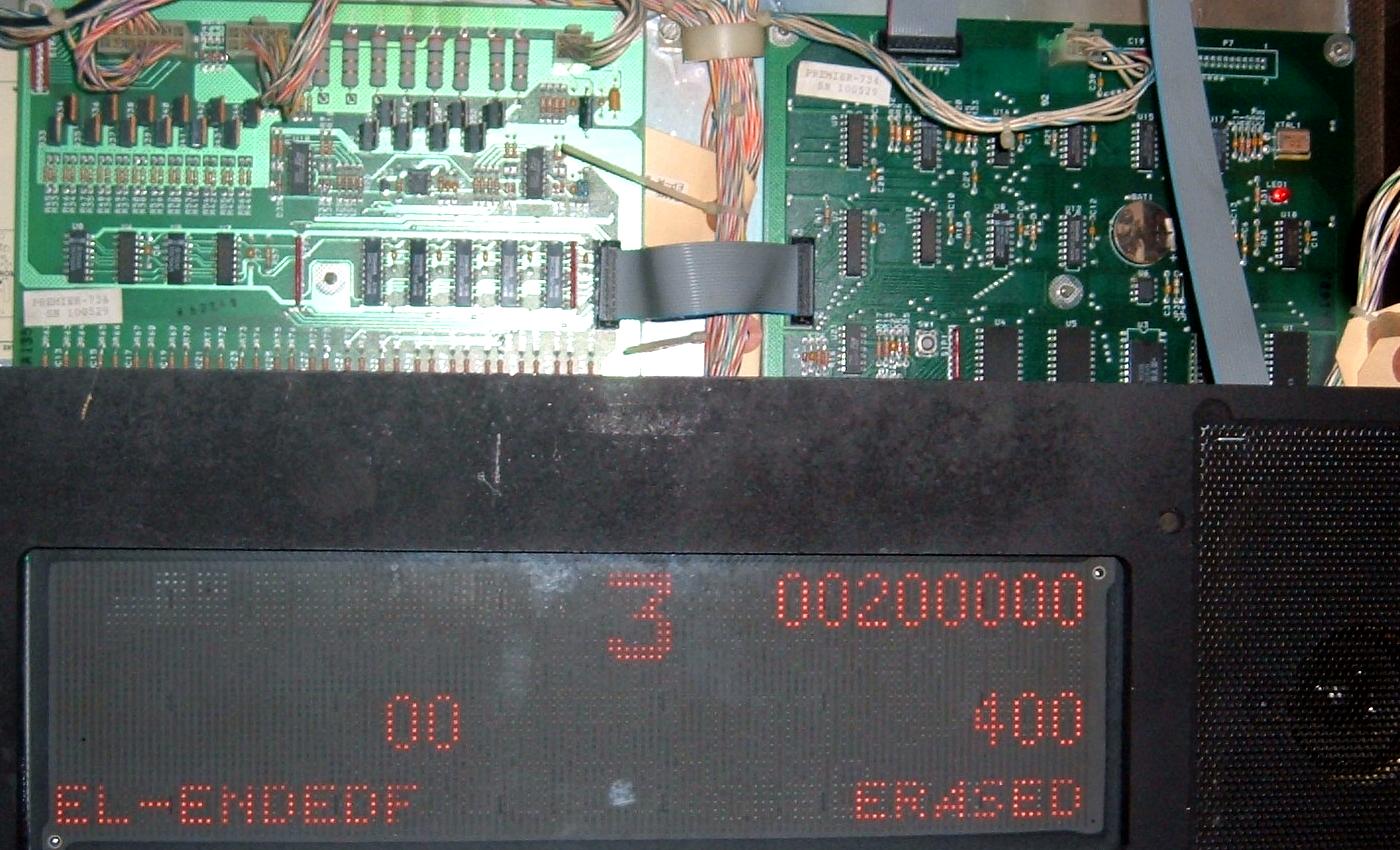
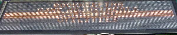
|
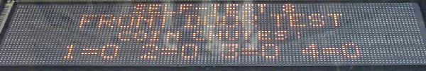
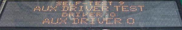
If the DMD shows garbage like this and the DMD controller LED is locked on, chances are good the U8 GAL chip is bad. |
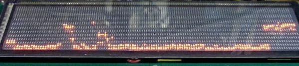
|
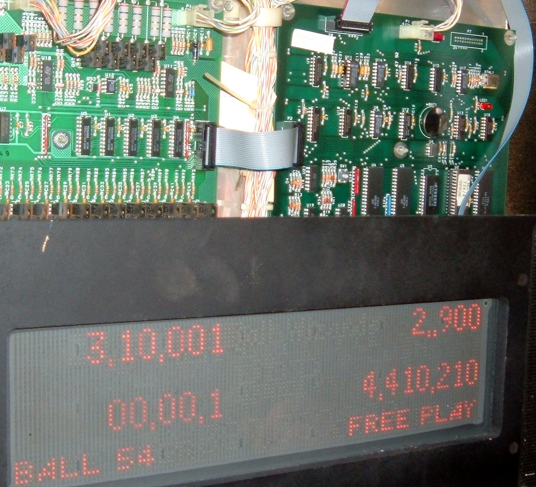
|
A properly booting CPU board. |
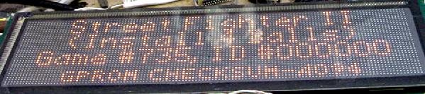
|