3a. When Things Don't Work: Power-On LED Flashes (Non-Working CPU),
Corrupt Memory.
A concept transplanted from the earlier and very successful
Bally "-35" CPU board was the power-on LED flashes. The new 6803 CPU board also
had power-on flashes to diagnose problems with the board. This
power-on flash concept stayed until
Escape from Lost World, Blackwater 100, Truckstop and Atlantis,
when Bally took a step back. Instead of doing the power-on flashes,
these games had one faint flicker at power-on if the CPU board passed power-on
diagnostics. If the board found a problem, then the flash sequence starts.
CPU LED Flash Overview by Game.
- Beat the Clock: 8 LED flashes (No U2 ROM).
- Motordome: 9 LED flashes.
- Strange Science: 9 LED flashes.
- Heavy Metal Meltdown: 9 LED flashes.
- Blackwater 100: No LED flashes.
- Escape from Lost World: No LED flashes.
- Eight Ball Champ: 8 LED flashes (no U2 ROM).
Fuse FU5 removed - 6 flashes
Fuse FU4 removed - 7 flashes
CPU Board Power-On LED Flash Codes.
The number of game ROMs used and the era of the 6803 determines the
number of power-on CPU board LED flashes. Flash code verification
thanks to Clive! Here is the layout:
- Eight power-on LED flashes.
Single CPU game ROM at U3. Includes Cybernaut, Eight Ball Champ, Hot Shotz,
and Lady Luck.
- Nine power-on LED flashes.
CPU game ROMs at U2/U3. Includes Motordome, Karate Fight,
Black Belt, Special Forces, Strange Science, Hardbody,
Party Animal, Heavy Metal Meltdown, Dungeons & Dragons.
- No initial power on LED flashes
(though sometimes a faint power-on LED flicker can be seen).
Escape from the Lost World, Blackwater 100, Truck Stop, Atlantis. If CPU
board passes all power-on tests there are no flashes. If an error is found,
up to nine LED flashes will be seen.
Clive tells us for all the 6803 games except Lost World, Blackwater 100, Truck Stop,
Atlantis, the tests work like this.
A test is performed, then the LED is flashed once if the test passes, then another test
is performed, the LED is flashed again if the test passes, and so on and so on, until all
eight or nine tests are complete. If a test fails, the code actually
loops forever within the test routine detecting the fault, and no flash is
shown for this test.
On the last four games
Escape from the Lost World, Blackwater 100, Truck Stop,
Atlantis, things are done a bit differently.
Bally states, "if there is +5 volt DC and +14 volts DC on the
CPU board, the game performs a self-diagnostic test. When no problems
are encountered, the game powers up immediately without flashing the
LED on the Control Board. When a problem is detected, the LED will flash
the appropriate number of times for each diagnostic test passed (I.E. if
the LED only flashes three times, U4 is probably defective, using the
table of power-up sequences below."
This is done because
as each test is performed, the number of errors encountered is logged.
At the end of testing the hardware, the routine that flashes the LED
checks this log to determine if it has any flashes (errors) to report.
If there are errors, it flashes the LED from the
last test passed to indicate where the problem lies. Also note on these
last four games an initial power-on faint flicker can be seen. Yet there is
nothing in the ROM code that's deliberately causing the power-on 'flicker'.
It just a buy-product of accessing the ports a number of times.
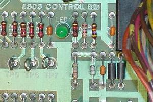
The 6803 Control Board's ever familiar power-on green LED.
|
Eight LED Power-on Flashes Decoded.
Here are the meaning of the LED codes for games Cybernaut,
Eight Ball Champ, Hot Shotz, Lady Luck and Beat the Clock.
These games all had a single EPROM at U3 (no U2 EPROM).
- 1st flash - CPU internal Static RAM test on U1 (6803, 0x0080-0x00ff).
- 2nd flash - U3 program ROM validated.
- 3rd flash - U4 (6116 CMOS) Static RAM test. No 3rd flash, check
resistor r27 (80 ohms 2 watts).
- 4th flash - U8 (6821) PIA-0 test.
- 5th flash - U7 (6821) PIA-1 test.
- 6th flash - U1 (6803) internal timer test.
- 7th flash - U8 (6821) test for lamp phasing logic test 'B' phase of CPU controlled
lamps. Fuse F5 on power supply provides
the phase B signal to the CPU board for U8 (6821), U12 (4584).
- 8th flash - Zero cross test U1 (6803), U11 (4011), U12 (4584) for lamp phasing
logic test 'A' phase of CPU controlled lamps. Fuse F4 on power supply provides
the phase A signal to the CPU board for U1 (6803), U11 (4011), U12 (4584).
Nine LED Power-on Flashes and (No Power-on Flashes) Decoded.
All other games use a nine LED flash code system, including the last
four games that have no power-on flash system (unless a problem is
encountered). These are games that had an EPROM at both U2 and U3 on the CPU board.
- 1st flash - CPU internal RAM test on U1 (6803).
- 2nd flash - U2 program ROM validated.
- 3rd flash - U3 program ROM validated.
- 4th flash - U4 (6116 CMOS) Static RAM test. No 4th flash, check
resistor r27 (80 ohms 2 watts).
- 5th flash - U8 (6821) PIA-0 test.
- 6th flash - U7 (6821) PIA-1 test.
- 7th flash - Checks internal display interrupt generator U1 (6803).
- 8th flash - Checks U12 (4584), U8 (6821) for lamp phasing logic test 'B' phase of CPU controlled
lamps. Fuse F5 on power supply provides
the phase B signal to the CPU board for U12 (4584), U8 (6821).
- 9th flash - Checks U1 (6803), U11 (4011), U12 (4584) for lamp phasing
logic test 'A' phase of CPU controlled lamps. Fuse F4 on power supply provides
the phase A signal to the CPU board for U1 (6803), U11 (4011), U12 (4584).
NO Led Flashes.
Remember the 6803 games Escape from the Lost World, Blackwater 100, Truck Stop,
and Atlantis will have no flash codes unless the CPU board thinks
there is a problem. These games were made when Williams bought Bally,
and Williams had a different philosophy than Bally when it came to
flash codes.
Corrupt Memory.
The memory get corrupt from a bad battery and or bad RAM chip,
and the game won't work properly. For example, game will boot up,
but won't accept credits or start a game. Solution: reset the
adjustments or go thru the adjustments looking for nonsensical
values (8 balls per games for example), and reset that adjustment
to the correct value.
3b. When Things Don't Work: 6803 ROM Software and Jumper Settings.
CPU Board Jumper Settings JW1 to JW6.
Jumpers W1 to W6 on the CPU board determine the size of
the U2/U3 game EPROMs (both of these EPROMs should be the same size,
and some games only use the U3 EPROM).
- 2732 U2/U3 EPROMs: Jumpers JW1,3,5=in, JW2,4,6=out.
- 2764 U2/U3 EPROMs: Jumpers JW5=in, JW1,2,3,4,6=out.
- 27128 U2/U3 EPROMs: Jumpers JW2,4,6=in, JW1,3,5=out.
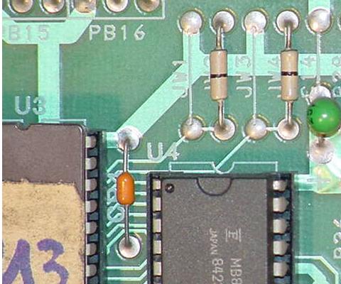
The 6803 Control Board's jumpers JW1 to JW4, by the U3 and U4 chips
in the upper right corner, below the flipper relay.
|
The 6803 Control Board's jumpers JW5 to JW7. JW5/JW6 is between U9/U10,
and JW7 is below and to the left of U1 (the 6803 CPU chip).

|
CPU Board Jumper Setting JW7.
Jumper JW7 should always be out, as this jumpers pulls up the
processor serial receiver pin via a 3.3k pull-up.
CPU Board Jumper Settings JW8 to JW11.
There are two general purpose light driver circuits and
two general purpose drive lines (switches etc).
These are 'open-ended' and for expansion.
There are two spare "General Purpose" (GP) PIA port output lines,
and these can be left alone or linked into the driver circuits
(game specific).
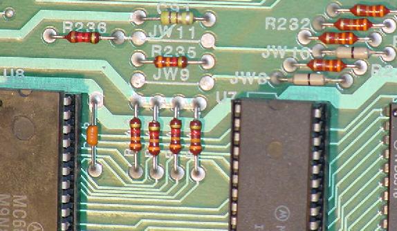
The 6803 Control Board's jumpers JW8 to JW11, by the U8 and U7 6821 chips, in the
top middle of the CPU board.
|
These four individual driver circuits on the CPU board that are not
connected to *anything* at their logic input.
However, their outputs are wired to the connector and pins numbers
listed below. Two are light solenoid GP (General Purpose) drivers,
and there are two light switch driver circuits. They are
"spare driver circuits" the board designers incorporate in the game
for use if the game needs it.
- Jumper JW8 in: PB14 drives GP driver circuit 1 (J9 pin 9).
- Jumper JW9 in: PB14 drives light switch drive 1 (J4 pin 1).
- Jumper JW10 in: PB15 drives GP driver circuit 2 (J7 pin 4 and/or J6 pin 7).
- Jumper JW11 in: PB15 drives light switch drive 2 (J2 pin 19).
So how are these spare drivers used? Well also on the CPU board are two spare PIA
outputs, PB14 and PB15, from the 6821 PIA at U7. These too are not
connected to anything. This is where the jumpers come in. If the game
needs them they can be linked up using the jumpers listed above, and have
the software control the driver circuits via the PIA outputs PB14 and PB15.
For example, here are the jumpers for Escape from Lost World and Strange Science.
Note jumpers JW1 to JW6 are the same for both games (they both use the
same size game EPROMs at U2/U3). But the JW8 to JW11 jumpers are interesting:
| Game |
LED
Flashes |
U2
ROM |
U3
ROM |
ROM
Size |
Jumpers
IN |
| Eight Ball Champ |
8 |
none |
Yes |
27128 |
2,4,6,8,10 |
| Beat the Clock |
8 |
none |
Yes |
27128 |
2,4,6,9,10 |
| Lady Luck |
8 |
none |
Yes |
27128 |
2,4,6,8,10 |
| Motordome |
9 |
Yes |
Yes |
27128 |
2,4,6,8,10 |
| Black Belt |
9 |
Yes |
Yes |
27128 |
2,4,6,8,10 |
| Special Forces |
9 |
Yes |
Yes |
27128 |
2,4,6,9,10 |
| Strange Science |
9 |
Yes |
Yes |
27128 |
2,4,6,9,10 |
| City Slicker |
9 |
Yes |
Yes |
27128 |
2,4,6,9,10 |
| Hardbody |
9 |
Yes |
Yes |
27128 |
2,4,6,9,10 |
| Party Animal |
9 |
Yes |
Yes |
27128 |
2,4,6,9,10 |
| Heavy Metal |
9 |
Yes |
Yes |
27128 |
2,4,6,8,10 |
| Dungons & Dragons |
9 |
Yes |
Yes |
27128 |
2,4,6,9,10 |
| Escape Lost World |
9 |
Yes |
Yes |
27128 |
2,4,6,8,10 |
| Blackwater 100 |
9 |
Yes |
Yes |
27128 |
2,4,6,9,10 |
| Truckstop |
9 |
Yes |
Yes |
27128 |
2,4,6,9,10 |
| Jumper |
Escape
LWorld |
Strange
Science |
D & D |
BW100 |
8Ball
Champ |
Party
Animal |
Heavy
Metal |
CPU
ROM Size |
27128 |
27128 |
27128 |
27128 |
27128 |
27128 |
27128 |
| JW1 |
out |
out |
out |
out |
out |
out |
out |
| JW2 |
in |
in |
in |
in |
in |
in |
in |
| JW3 |
out |
out |
out |
out |
out |
out |
out |
| JW4 |
in |
in |
in |
in |
in |
in |
in |
| JW5 |
out |
out |
out |
out |
out |
out |
out |
| JW6 |
in |
in |
in |
in |
in |
in |
in |
| |
JW7 |
out |
out |
out |
out |
out |
out |
out |
| |
JW8 |
in |
out |
out |
out |
in |
out |
in |
| JW9 |
out |
in |
in |
in |
out |
in |
out |
| JW10 |
in |
in |
in |
in |
in |
in |
in |
| JW11 |
out |
out |
out |
out |
out |
out |
out |
Notice the difference in jumpers JW8 and JW9 on these games.
This has to do with how one game has optic switches for the ball
trough, and the other does not, or how one game uses more playfield
switches than another. For example, the additional PIA ports are
used to drive these optic switches on Strange Science.
6803 Pinball ROM Software.
Since the Williams pinball web site never got around to putting up the
Bally 6803 software, it is available here. These files have not been
personally tested by me, so if anyone finds any errors, please email
me with the problem at
cfh@provide.net.
Games with U2 CPU game ROM only (8 Flash CPU LED):
Games with U2 and U3 CPU game ROMs (9 Flash CPU LED):
Games with U2 and U3 CPU game ROMs but only intial faint CPU LED flicker:
3c. When Things Don't Work: Leon's 6803 Test EPROM (fixing a Dead CPU board).
The purpose of the test EPROM is to
repair the CPU board out of the game and on the work bench, and at the same
time test all of the outputs of the lamp and driver transistor sections.
We will start by testing
the special output ports of the 6803 and the connected PIAs,
followed by a memory test, and then the lamps and coils outputs.
This gives us a way of testing all circuitry in
between the IC output ports and the board's connectors. The game's lamps and
coils are simulated on the bench by a series of LEDs plugged directly into the
CPU board's connector.
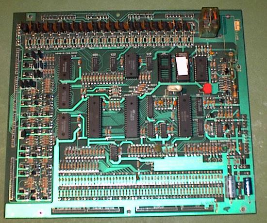
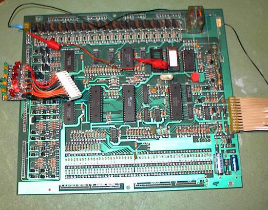
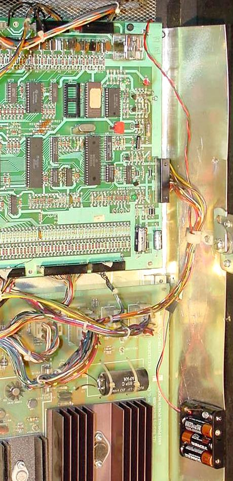
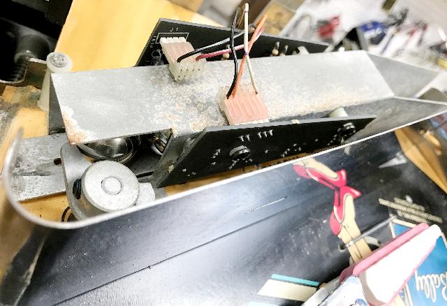
The 6803 control board, normally a
battery is at the top in the right corner.
Testing the 6803 On the Work Bench - Getting a Power Supply.
The best way to use the test EPROM is with the CPU board out
of the game and on the work bench. But to do this, a +5 and +12 volt
power supply is needed. I use an old computer power supply, as these
are plentiful and cheap (any decent computer store should be able
to sell you a used AT or ATX power supply for around $15).
Alternatively an old video game switching power supply
(about $25) can be used.
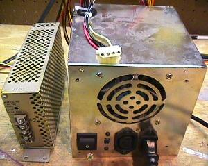
On the left is a video game switching power supply.
On the right is a used computer power supply. Either
will work fine for a test fixture. Note the computer
power supply connector on top of the box is the one
that will supply our +5, GND and +12 volts. This plug
was used to power drives (hard drive, CD rom, etc).
Red is +5, black is GND, and yellow is +12.
|
|
When it comes to buying a computer power supply, remember there are
two types, AT and the newer ATX. It is better to have the older AT style, as
this power supply will have a physical switch to turn it off and on.
If the power supply does not have a 20-pin connector (two rows of 10 side by side),
you don't have an ATX power supply. Also the ATX style usually has no AC power
switch. On the other hand, a true AT supply will have a 120V power switch
connected to it. And when an AT is switched on, the fan runs and it stays
on, whether there is a power load or not.
The newer ATX style has a "soft switch" (which allows the Windows
operating system to automatically turn the computer off),
as it relies on signals from the motherboard to power it off and on.
In order to turn "on" an ATX power supply, the large 20 pin connector
must have its green PS-ON wire (pin 14) tied
to the black COM ground wire (pins 13 or 15-17).
Note that pin 1 is the "square" pin, and pin 11 is directly across from pin 1.
Tying this green wire
to a black COM wire will turn the power supply permanently "on", so
you could install a physical switch between these two wires as a
power switch.
Also remember switching power supplies like the AT and ATX
are switch-mode power dependant on load.
This means that the power is switched on and off rapidly to meet the
load. If there is no load (nothing attached), the output power is switched off.
So using a DMM (digital multi-meter) alone to test the power supply output
voltages may not be enough draw to make the power supply turn on.
Warning!!
Be careful when you hook up the voltages to your MPU board. If you short
+12 volts to +5 volts (for example), you will probably destroy all the chips
on the MPU board! Also be careful when you hook up +12 volts. It is
VERY easy to short test points. This may damage the MPU board too! (Unlikely,
but let's not risk it). So be careful, and double check your connections before
you turn the power supply on.
In any case, all you need to do is connect the power supply
to a wall plug (110 vac), and put aligator clips on the GND,
+5 vdc and +12 vdc. That's all you need to power up a Bally 6803 CPU
board on your workbench.
On a computer power supply, the best way to do this is to use
one of the plugs that connected to the computer's hard drive,
floppy drive, or CD ROM drive. There are usually at least
three of these 4 pin plugs on each computer power supply.
These plugs have two black wires, and one red and one yellow wire.
The two black wires are ground, the red wire is +5 vdc, and the
yellow wire is +12 vdc. I used some crimp-on round male connector
pins and jammed them into the plug. Then I connected these to
aligator clips, which ultimately go to your MPU board.
CPU Board Test Points.
Here are the test points for the CPU board. Use these to connect
the external power supply, or just for checking voltages in the game.
- TP1 = 5 volts DC (4.9 to 5.2 volts DC), J1 pins 10-12.
- TP2 = Ground, J1 pins 7-9 and J4 pins 5-6.
- TP3 = 12 volts DC (unregulated 12 to 18 volts DC), J1 pin 6.
- TP4 = Battery voltage (3.5 to 4.5 volts DC) - Not needed.
Connecting Power to the CPU board on the Bench.
Because some ground returns on the CPU board
are separated (for example the return for the lamps and the coils),
we need to bring these returns together to logical ground.
Here a drawing how things are connected.
The transformer (in red) 2x12 volts AC is not
needed to run the test, it is only needed to run the board with
the game roms. On the board are some jumpers. Use these settings
to run the test program:
- W2, W4, W6 = in
- W1, W3, W5 = out
These are the settings to use 27128 type EPROMs in U2 and U3.
About all the games have 27128 EPROMs as the game ROMs, so most
likely you won't have to change any jumper setting.
To connect the external power supply to the 6803 CPU board
using Leon's Test EPROM, use these power connections. Note connector
J1 is on the CPU board at the lower right corner, and J4 is at the
upper left corner.
- J1 pins 10,11,12 = +5 volts, TP1
- J1 pins 7,8,9 = Ground, TP2
- J4 pins 5,6 = Ground
- J1 pin 6 = +12 volts, TP3
An Additional Power Source.
Much like the 1977-1985 Bally 6800 MPU board, the 6803 CPU
board needs an additional power source to make it think
it's really mounted in the game and not on your work bench.
What is needed is a transformer that delivers 2x12 volts AC
(a 24 volt transformer).
With this transformer, the middle tap (0 volts) is
connected to ground (J1 pins 7-9),
and both 12 volt outputs to J1 pins 3 and 4 respectively.
But this duel 12 volt AC power is only needed if you're running
the game ROMs. So for our test bench scenario with the Leon
Test EPROM, this is not needed (unless you want to run the
Game ROMs on your work bench, which isn't a bad idea as a last
test). Radio Shack sells a 2x12 (24 volt)
transformer for about $7 that works great for this.
Important! If using the Test EPROM with the CPU
board installed in the game, remove all CPU board connectors
except J1. Otherwise the solenoids/lamps can all engerize at once.
Download the Test EPROM.
The test EPROM can be downloaded
here.
Burn the ROM into a 27128 EPROM, and place in socket U3
on the 6803 CPU board. The other game EPROM at U2 can remain
in its socket, or may be removed.
Using the Test EPROM.
Make sure the CPU board jumpers are set as indicated above.
Plug the 27128 Test EPROM into the CPU board at position U3
with the EPROM's notch correctly oriented.
Hook up the external power supply to the CPU board as specified above.
Power on the board and the CPU board's LED will start blinking
rapidly. The LED is connected directly to an output of the CPU
chip at U1 pin 10 - there is only one transistor (Q1, 2N5385) and
three resistors (R10=47k, R3=1k, R1=568 ohms) between the CPU output
and the LED. In case the LED does not blink, first check if there is
a signal at Pin 10 (U1) using a logic probe. If this is the case, the
transistior or the LED itself is bad. If the LED blinks the Test EPROM can
control the outputs of the CPU ports at pins 8,10-20. On
the PIAs (U7 and U8) the output are pins 2-17,19.
What if the Test EPROM Does Not Start Blinking? - Reset Signal
When the test does not start up, remove the test EPROM from U3.
Also remove the game ROM (if present) from U2.
The U1 6803 chip does not need many signals to start up. Check
the U1 CPU chip at pins 4,5,6 for +5 volts.
Pin 6 can be a likely problem, as this is the reset line.
Reset is fed from +12 volts through
transistor Q2 and Q3. When capacitor C1 (6.8 mfd) is
charged at boot up, this will launch Q4 (2n3984) and which opens Q5 (2n4483),
thus bringing +5 volts to U1 pin 6 as the reset. All reset semi-conductor
part to check:
- C1: 6.8 mfd (non-polarized)
- Q2,Q6,Q4: 2n3984
- Q3,Q5: 2n4403
- D1: 1n958b (7.5 volts, 1/2 watt)
- D3: 1n4148 or 1n914
- D4,D5: 1n4606 (can substitute 1n4148 or 1n914)
If U1 pin 6 is not +5 volts, the reset circuit is not working.
The reset (pin 6) has to go low to 0 volts for just a moment
while the +5 volts stablizes at power-on. Then U1 pin 6 should
go high signaling a good reset.
If this is not the case check the parts above
and/or replace them.
The Clock Signal.
At U1 pins 2 and 3 is the clock signal, which should
measure about 1 volt at pin 3. Better yet, use a logic probe
and U1 both pins 2 and 3 should be pulsing. The clock signal is formed by
three elements: the crystal (3.58 mhz) and four capacitor (mainly C2,C3 both 27 pf,
and to a lesser extent C4,C5 which are .1 and 4.7 mfd respectively).
It is extremely rare that the clock does not work.
The Address and Data Lines.
After measuring the clock signal, power off
and on the CPU board again (the clock signal is sensitive and
touching the pins when measuring can influence the normal working
of the CPU). Now check the outputs of all U1 pins from 21 to 40.
These are the address lines and the multiplexed address/data
lines. Find on all these pins between 2 to 4 volts with a DMM,
with only pin 39 as an exception at 1 volt.
If any signals from pins 21 to 29 are missing the 6803 is likely bad.
If U1 pins 30 to 37 are missing expect that U5
or U6 is bad. If one or some of the others are missing, first
bend upward the culprit pin, and check again at U1: if the signal is
still missing, the 6803 is bad. If with the pin bended upward the
signal is present, there is a short on the CPU board dragging
down that signal. Find the short
by eliminating some connected elements, by unsoldering them or by
cutting temporarily some traces (unfortunately there is no other
way to find such a problem).
If all U1 signals check out, replace the Test EPROM at U3 and try again.
Is there activity with the test EPROM in place?
IF the LED still does not blink, check
the signal at the U3 Test EPROM. The Test EPROM data
lines and address lines should be 2 to 4 volts at U3 pins 1-13, 15-19, 22.
At U3 pins 14 and 20 there should be zero volts.
And at pins 21,23,24 there should be 0.5 volts.
Lastly check the address signals at U3 pins 1-8, which
come from the demultiplexer chip U6. If missing
one of these signal the U6 chip is bad, or the EPROM is bad.
If missing a data signal at pin 9-17, the data demultiplexer chip
at U5 is bad. This only leaves U3 pin 22
(the select signal); check U9 and U10 which feeds U3 pin 22.
Test EPROM is Blinking the LED: Checking the PIA/CPU Outputs.
Now that the test EPROM is
running, we can check both PIAs at U7 and U8. Their output pins 2-17,19
will be pulsing up and down rythmically between 0 and 5
volts (this is a function of the Test EPROM, which allows easy
testing of the PIA chips).
If there is one pin not pulsing, bend the pin upwards (out of the socket),
and check it again at the chip. If still mising the PIA is bad.
If it's now pulsing when bent up and out of the socket,
then there is a short on the CPU board on that output line.
As we have done with the reset line test,
look for the short by removing potentially bad component
that connect to that PIA output line. Use the schematic to find
the connecting elements, and disconnect them one
by one. The easiest way to do this is by unsoldering or temporarily
cutting a trace. Also check the
CPU address/data lines on the PIAs which are at pins 8,10-12,13-20.
If there is a PIA that is
miss ALL output signals, the PIA is probably bad, or one of the
select signals is missing. The select signals arrive at pins
21-25,35,36 and should be between 2 and 4 volt.
These select signals were already checked, and
the only reason they are missing at the PIA is usually a bad contact in
the socket or a broken trace. Except for pins 23,24 these
address signals pass by two gates at U10,U11,U14. Use the
schematic to see wich gate are used and replace IC as needed.
Now we can assume you
have a working board with all basic signals present. Time to go
to the second part of the test EPROM: the memory test and driver elements
tests.
The Memory Test.
The memory test is
launched by the push button on the CPU board. When run the LED
stops blinking and remains steady for a short while (which can be
either "on" or "off"). Afther a short moment the led
starts blinking again in a slow rhythm more "on" then
"off", this means the memory test passed Ok, and
the Test program is now doing the driver tests.
If the LED does not restart blinking
there is something wrong with the U4 6116 CMOS memory chip.
Before replacing the 6116 chip, take a look at the signals at U4.
Again we find mostly all the address and data
lines pulsing and between 2 and 4 volts with a DMM. Other signals
at U4 pins 14,20 are 0 volts, and 0.5 volts at pins 21,23,25. The
only signal that is new here is the selection signal at pin 18.
If this is missing look at U9 and U10 which drives U4 pin 18.
If a signal at the input of the U9/U10 gates is present yet missing at
output of U9/U10 (use schematic), replace the chip.
Testing the Switch Matrix.
The switch matrix is at connectors J4 (playfield switch return)
and J3 (cabinet switch return), and J5.
We can test the PIA outputs and inputs by just testing the PIA's output mode.
The output port is tested because it is easier, and it is not possible that
a complex chip like a PIA to have ouputs without it having
inputs too.
The switch matrix is tested using the
basic test mode, where the LED is blinking fast, as the J3/J4/J5 connector pins
are directly tied to the PIA pins and the CPU port (only a
resistor is used between these two, as security if at anytime a pin
should be at ground, so not to damage the chip).
To test the switch matrix, restart the test EPROM, and while the LED is
blinking fast, measure these connector signals using a DMM (digital multi-meter):
- J3 pins 4-15: between 1 and 2 volts
- J3 pin 1: 5 volts
- J3 pin 2: 0 volts
- J4 pins 2-15: between 1 and 2 volts
- J4 pin 1: +5 volts if you have jumper W8 in place
(pin 1 will be lower if jumper W9 is instead in place)
- J5 pins 7-15: between 1 and 2 volts
- J5 pin 1,2: +5 volts
- J5 pins 3,4: 0 volts
- J5 pin 6: no connection.
Testing the Score Display Drivers.
The score display are at connector J2,
almost directly inline to PIA U7. The PIA U7 pins 9-13 pass
through U13, and if on signal is missing, look at chip U13 (or
just replace it). With the Test EPROM running,
again measure the PIA U7 at pins 2-18 for 1 to 2 volts
using a DMM. U7 pin 1 is a constant at 5 volts.
Testing the Lamp Driver Transistors.
To check the controlled
lamps drivers ideally we need some extra hardware. On the lamp/solenoid
connectors we can use a LED strip that will substitute for
the lamps and the solenoids. The LED strip is a load and visual
indicators.
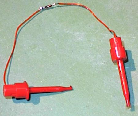
As seen below, you can make an entire strip of LEDs
to test all pins on a connector at a time. Or an easier way
is to just make a single LED/resistor with two hooked test
leads, testing one connector pin at a time.
Note you should test the direction (flat side)
of the LED in this circuit. In one direction the LED will
work, in the other it will not. Here's the basic hook up
diagram:
If you are up for the work, an entire strip of LEDs can be
made too. This is certainly more convenient, but of course
is added work.
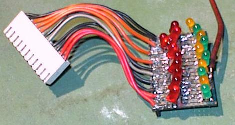
In the pictures above, the single
red lead of the self-made circuit board connects
to +5 or +12 volts.
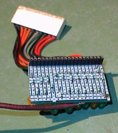
The large .156" Molex connector goes on the CPU board's heavy coil connector
pins J6,J7,J8,J9 (across the top of the CPU board).
On the back side of the home-made board there is another .100" female
Molex connector strip for the lamp driver connectors J10,J11,J12,J13
along the left side
of the CPU board. We can see also the 470 ohm resistors on the back
side of the home-made board.
Furthermore we need
another small adapter, which will connect a 2200 ohm resistor between
ground and U14 pin 19. The resistor is wired
with two mini hooks to connect U14 pin 19 easily to ground.
After installed on the CPU board, the whole
contraption looks like the picture below.
Note the resistor connected between ground and U14 pin 19,
the LED board on lamp connector J12
(using the .100" connector strip at the back of the LED board).
Testing the Lamp Outputs.
The LED board is
connected at J10, J11, J12 and J13, all programmed lamp
connectors. Every time the Test EPROM's driver test is run *all* LEDs of
the LED board will light on stay "on" (except of
course where the connector key is located):
- Connected to J10,
all LEDs light except for pin 5 (the key).
On J10 during the basic test, 4 LEDs will blink,
which includes 1,2,7,16.
- Connected to J11,
all LEDs light except 5 (key).
- Connected to J12,
all LEDS light except 5 (key).
- Connected to J13,
All LEDs except 9 (key).
Note during the basic test *no* LEDs may go "on" (excepted the four
mentioned on J10). If only some LEDs go on during basic test that
means one of the lamp transistor (2N5060) is probably bad.
On the schematic it is easy
to find which connector pin (LED) is goes to which 2N5060.
Also remember that all lamp transistor are
driven by three chips at U15,U16,U17, which can fail too.
In case a LED does not light, remove
the LED test strip and measure the center leg of the
suspect 2n5060 lamp transistor
with a logic probe. If the 2N5060 transistor is
receiving a pulse at its middle lead, the 2n5060
transistor is bad. If no pulse is seen at the middle leg,
check at the output of the driving chip (U15,U16 or U17).
Use the schematic to find which chip is controlling which 2n5060.
If there is no command coming out the IC replace it, if
all outputs at that IC are missing again replace the chip.
If there is an output pulse, check the resistor between the 2n5060 and the
chip's output pin (as that is the only thing between them). Aside
from that, the only thing left is the driving PIA.
Testing Solenoid Connectors
For the solenoid outputs we can again use
the LED test strip on the solenoid connectors J6,J7,J8,J9. The
results should be:
- J6: LED 1,7 will blink during the
basic test. LEDs 2,3,4,5 will blink during the driver test.
LED 6 never lights.
- J7: LED 3,4 will blink during
basic test. LED 1,2 lights during the driver test.
LEDs 5,6,7,8 will no light ever.
- J8: LED 1,5 will blink during the
basic test. LEDs 2,4,6,7 blink during the driver test.
LED 3 never lights.
- J9: LED 9,10 blink during the basic
test. LED 1,2,3,4,6,7,8,11 blinks during the driver test.
LED 5 never blinks with CPU board jumper W8 in place.
If you have jumper W9 installed instead, lED 9 will
not blink during the basic test.
Other Notes: First the LEDs which blink during the
basis test will blink all together. Then LEDs that blink during
the driver test will blink one after another, giving a
"running light" effect. During the test that the LEDs should
light, it MUST blink; a steady and solid "on" means the
driver transistor is bad. All basic commands come from U14.
When you have a LED that will not blink, check first the outputs of
U14 pin 1-16. If pulsing, you have a fault
at the driver chip (CA3801) or the driver transistor. Follow
the command using schematic sheet five.
Extra CPU Board Control Circuit.
For reasons not
explained here, there is an extra circuit on the CPU board which
uses a 2x12 volt AC signal connection directly from the transformer. This
signal will generate interrupts, amoung other things. Sometimes this
circuit fails.
Look at U12 pin 6,2 and there you must find a signal of 2 volts. If
this voltage is not present, replace chip U12. Also check
sheet 2 of the schematic for some other related elements (diodes
and resistors.)
Try the CPU board with the Game ROMs.
A last ultimate test on the bench uses the game ROMs instead
of the Leon Test EPROM. Unfortunately we need to
connect a 2x12 volts AC transformor to the CPU board
for this test. On the 2x12 volt AC transformer,
its middle tap (0 volts) set to gound (J1 pins 7-9), and
both 12 volt outputs are connected to J1 pins 3 and 4 respectively.
Again Radio Shack sells a 24 volt transformer that is perfect
for this task.
In addition, connect the +5/12 volt lead of the LED strip to one
of the transformer's 12volt AC connections. If the board starts up OK and
works fine, the LED tester should blink, as they represents the
programmed lights of the machine (which normally blink after power
up).
3d. When Things Don't Work: Replacing the Battery and CPU Board Battery Corrosion.
Remove the Original Battery.
The original rechargable NiCad battery should be cut off the CPU board
and thrown away as soon as possible. This battery is probably at least 15 years
old. If it hasn't leaked its corrosive guts, consider yourself lucky.
After the battery is cut off, it can be replaced with standard
Alkyline AA batteries and a battery holder. A blocking diode must
also be installed in the new AA battery holder to prevent the
CPU board from trying to recharge the AA batteries.
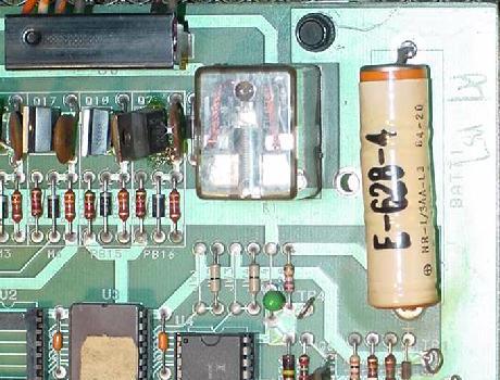
The NiCad battery on the CPU board in the upper right hand corner.
Remove this battery ASAP to protect the CPU board and its connectors
from battery corrosion!
|
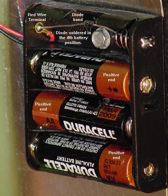
Note the inexpensive four AA battery holder shown below. These are
readily available at Radio Shack and other electronics stores.
But only use *three* of the four battery spots, and installed
a 1N5817 blocking diode as shown, with the band
towards the positive lead of the battery holder.
Note other diodes such as a 1N914/1N4148 or IN4001/1N4004
can be used. But the forward voltage drop of the 1N5817 is
only .2 volts, where the 1N914 or 1N4001 is .4 to .6 volts. This
means using a IN914 or IN4001 will show the batteries as
"dead" sooner than using a 1N5817 diode (you'll change the batteries
more often), since the output voltage drop from the battery holder's
batteries will be greater with a 1N914 or 1N4001 diode.
Using an inexpensive four AA battery holder, a 1N5817 blocking diode, and
three AA batteries as a remote battery holder for the CPU board.
|
The remote battery holder installed in the game (Eight Ball Champ).
Note the battery is installed as low as possible, and a fair distance
from the CPU board. A connector was also added to the battery wire
so it may be easily disconnected from the CPU board.
|
3e. When Things Don't Work: Using the 6803 Keypad for Diagnostics
and Adjustments
The "Registers".
All the games have
adjustments are stored in memory at U4 (6116 RAM).
Game prior to Motordome use a what Bally called "Registers"
(as in locations in memory), to identify each stored adjustment or audit.
Some computer geek must have come up with that name! Starting
with Motordome, Bally stopped using the "registers" nomenclature
(and audit were "scrollable" with the keypad).
A Bad Control Board Battery and Memory.
The memory stays in the RAM due to
a rechargable battery on the 6803 Control board (at this point
in these game's lives, this battery should be removed and replaced
with a remote AA battery pack, as shown here).
If the battery dies, the game will still boot and operate normally,
except of course all the audits and game adjustments will default
to factory setting. This can be seen easily because all the high
scores displayed in attract mode will be 5,555,555.
On occasion, a bad battery can cause "corrupt memory",
and the game won't work properly. For example, game will boot up,
but won't accept credits or start a game. The solution is
to replace the battery and to get the game manual first.
After the battery is replaced and the manual acquired, power the game
on. The first thing to check is the number of credits per game
in the adjustments. Press the small push button inside the coin
door, next to the volume control. This should put the game
into audits and adjustments. Using the manual and the 6803 keypad
(Dungeons & Dragons and prior), find the credits-per-play
adjustment, and make sure this adjustment is set to
a valid number! If this is not done, the game will probably
not accept credits, and won't start play! After the credits-per-play are
entered, set all the other game adjustments as desired.
Note some games like Eight Ball Champ won't "talk" unless the adjustments
are set correctly. For example, on Eight Ball Champ, adjustment 50
should be set to use the Squawk & Talk sound board (value=1), and sounds mode
adjustment 27 set (value=3), otherwise the game will not talk.
Also check the balls-per-game adjustment (EBC adjustment 23)
is set to a valid number of balls (one to five). Match can be turned on and
off (EBC adjustment 29 value=1) on these games, and the credit displayed on the game
(EBC adjustment 30 value=1) can be turned on and off.
All 6803 games also have a "free play" adjustment (EBC adjustment 42),
and if this is set to value 65, the game will start without coins.
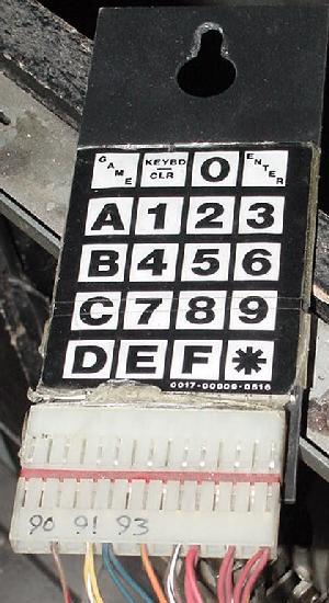
The infamous Bally 6803 keypad for audits,
adjustments, and diagnostics! (D&D and prior.)
|
Power-On Stuck Switch Test.
Starting with Blackwater 100, Bally incorporated a "stuck switch" test
at game power on. This was much like Williams had in their System11 games
at power on.
The Keypad - Portal to the Adjustments/Diagnostics.
All 6803 games except Escape from Lost World, Blackwater 100, Truckstop and Atlantis
use the keypad for adjustments and diagnostics (the above four games
use the flipper and start buttons instead of the keypad).
The 6803 keypad was an incredibly dumb idea. Bally's reasoning
for it was, "It allows the operator to go directly to a function or
adjustment, eliminating the tedious procedure of repeatedly
press the self-test button to look at a certain adjustment.
Of course pressing the self-test button gave the
operator time to chat with the local
repair expert and learn how he and Ernie always put chewin' gum
on the legs to keep the game from slidin'." (No kidding, they
really said that in the Eight Ball Champ manual!) With the
keypad, just punch in the Register number
on the keypad and the
information is shown on the score displays
(the "register" nomenclature was
used on games with 7 digit score displays, prior to Motordome).
That's all fine and dandy, but on games with numeric displays, going to
some discrete unnamed numbered adjustment directly doesn't really help if
the user doesn't have a manual with the list of Register numbers and
their meaning. Also
the keypad is connected to the game with a .156" Molex connector.
Hence the keypad can become disconnected from the game and lost
(finding a 6803 keypad for purchase is as rare as hen's teeth).
If the keypad is missing, there is effectively no way to enter the diagnostics,
audits, or adjustments!
Faking the Keypad (missing Keypad).
If the keypad is missing on your game, one can be constructed.
The keypad uses the switch matrix, crossing a row and column
to get a keypad number/letter. Below is the configuration,
information thanks to C.Woodruff.
| |
Switch Column |
| |
3 |
6 |
10 |
13 |
| 15 |
Game |
Keybd
/Clr |
0 |
Enter |
| 11 |
A |
1 |
2 |
3 |
| 8 |
B |
4 |
5 |
6 |
| 5 |
C |
7 |
8 |
9 |
| 1 |
D |
E |
F |
* |
| Row |
|
* Bold numbers above are the respective switch row and column numbers.
Non-bold text are the keypad buttons. Note the row with letters
"D", "E", "F" and "*" are not used in any of the 6803 games I know of.
For example, if you want the combination for keypad "1",
the pins connected are (row) 11, (column) 6.
Keypad "2" would be (row) 11, (column) 10, and so on.
And here is the color coding for the connector going to
the keypad:
- Pin 1 - n/a
- Pin 2 - n/a
- Pin 3 - Blue/Brown
- Pin 4 - Key
- Pin 5 - Yellow/white
- Pin 6 - Blue (two wires)
- Pin 7 - n/a
- Pin 8 - Orange/Green
- Pin 9 - n/a
- Pin 10 - Brown/White (two wires)
- Pin 11 - Red/Green (two wires)
- Pin 12 - n/a
- Pin 13 - Red/White (two wires)
- Pin 14 - n/a
- Pin 15 - Red (two wires)
The schematic for the 6803 keypad.
|
Enhanced Keypad Schematic.
Ingo Kramer (germany) created a PDF file of an enhanced schematic for
the Bally 6803 keypad
here.
He also did a layout for the keypad to remake them
here.
The coin door black test button and volume control.
|
Using the 6803 Keypad.
On all games except Escape from Lost World, Blackwater 100, Truckstop and Atlantis,
the keypad should be inside the game near the coin door. The cable is
long enough the keypad can easily be used outside of the game.
Here are the steps required to use the keypad. As you can see,
the procedure is not as easy as it could be (and this is one
reason the 6803 system is disliked):
- Press the black test button inside the coin door.
- On later 6803 games only, the CPU will now check all
the switches in the switch matrix.
- If any switch(es) are closed, the game automatically goes to
the Stuck Switch Test (test 94 in the match/credit display),
and displays the stuck switch numbers in all the player score displays
(if "00" is display, there are no stuck switches). If there are
stuck switch(es), the game will beep every second.
- Press the black test button again to exit the switch test.
- The game will go to Lamp test (90 in the match/credit display).
All the lamp matrix lights will cycle on and off.
- Motordome and later (games with 14 digit displays)
can use the "A" and "B" keypad keys to move (scroll)
forward and backward through the test numbers. Press the
Enter key to select.
- Press the keypad "KEYBD/CLEAR" button to exit the lamp matrix test
and go to "Keypad Mode" (audit number "00").
- The game enters "Keypad Mode"
and displays "00" in the match/credit display (on newer 14 digit alpha-numeric
score display 6803 games, the message "Bally Testing is Easy as ABC"). The game is
now ready for keypad entry.
- On 14 digit alpha-numeric 6803 games, categories will appear on the backglass
displays. Press ENTER once to select that category.
- To view/change a particular Register (note the "register" nomenclature
was only used on 7 digit score display games, prior to Motordome):
- Enter the Register number
on the keypad and press ENTER (as the Register number is typed on the
keypad, the numbers should echo in the match/credit unit). The current
value of the register will display in the player 1 display.
- If the Register
is an adjustment (and not an audit), type the new value for the register
(as the value is typed on the keypad, the numbers should echo in the player 2
display). Press ENTER to accept the new value, and both player 1 and player 2
values should be the newly entered number.
- If a mistake was made, just re-enter
the new value and press ENTER again.
- If the Register value is not valid, the
game will make a "buzz" error sound.
- Pressing CLR will re-start the self-test.
- Pressing GAME will keep any changed adjustments and go to game over
(attract mode).
Diagnostic Tests and the Keypad.
Here are the diagnostic test numbers to enter on the keypad,
and their descriptions. Note newer 6803 games
have additional tests that the earlier games may not have.
For example, newer 6803 games have a single lamp test,
single soleniod, and Game ROM ID test.
For all tests except the display test, the Function number is
shown in the match/credit display.
Summary of Diagnostic Test Numbers.
- 90 = Lamp test.
- 91 = Display test.
- 92 = Solenoid test.
- 93 = Sound test.
- 94 = Stuck switch test.
Diagnostics in Detail.
- Lamps (Function 90) - All the lamps in the lamp matrix are turned
on and off together, until the test is exited. The "A" phase is displayed
first, followed by the "B" phase. Press "enter" or "keybd/clr" to exit this test
and proceed to the next test.
- Single Lamps (newer games only) - Lights one lamp at a time and
also displays the SCR (lamp driver) number and connector ID on the score
displays. Press "A" to advance to next lamp, or "B" to back up to the previous
lamp, or "C" to cycle.
- Displays (Function 91) - Each score display will cycle from "0" to "9"
in all the digits, until the test is exited by pressing "enter" or "keybd/clr".
- Solenoids (Function 92) - All of the game's coils are energized in sequence
(as defined by their solenoid number). The flipper relay is also activated
during this test, so the cabinet flipper buttons should work too.
Press "enter" or "keybd/clr" to exit this test and proceed to the next test.
- Single Solenoids (newer games only) - Energizes one solenoid at a time.
Press "A" to advance to next coil, or "B" to back up to the previous coil.
- Sound (Fuction 93) - the 6803 Controller board will "talk" to the
sound board, and about once a second it will generate a buzzing noise.
Press "enter" or "keybd/clr" to exit this test and proceed to the next test.
- Game ROM ID (newer games only) - Displays ROM(s) ID numbers.
- Switches (Function 94) - if "00" is flashing in all the player score
displays, no switches are closed. Any other number than zero shows
which switch number is closed. Press test button inside the coin door
to exit this test.
3f. When Things Don't Work: Checking Transistors and Coils
(stuck on coils and flashlamps).
SE9302/2N6045/TIP122/NTE263 solenoid driver transistors.
|
3g. When Things Don't Work: the Power Supply (Test Points and Repair).
Power Supply Test Points.
Here are the test point values for the 6803 power supply:
- TP1 = +5 volts DC (4.9 to 5.2 volts)
- TP2 = 170 to 190 volts DC (final score display voltage)
- TP3 = 230 volts DC unregulated (input voltage for score displays)
- TP4 = +43 volts DC (40 to 60 volts, solenoids)
- TP5 = +14 volts DC unregulated (11 to 16 volts)
- TP6 = 11 volts AC (A zero crossing for feature lamps)
- TP7 = 11 volts AC (B zero crossing for feature lamps)
- TP8 = 6.3 volts AC (5.8 to 6.8 volts, General Illumination lights)
- TP9 = 6.3 volts AC (5.8 to 6.8 volts, General Illumination lights)
- TP10 = Ground
Cold/Cracked Solder Joints.
A common problem is
cold and/or cracked solder joints on the power supply board at connector J3
(but reflow all the power supply connectors).
Also commonly seen is cold/cracked
solder on the fuse boards (fuse board exists on some games,
mounted on the left side of the backbox), power supply ground connector
(this is the spade lug connectors below the transformer) which
can cause some really spooky problems.
Fuse Board.
A seperate fuse board mounted on the inside left of the backbox.
It's definitely in Dungeons & Dragons, Special Forces, Escape from the Lost World,
Heavy Metal Meltdown, Blackwater 100 and Atlantis.
Very common to have cold solder joints on this board too.
Wiring Looms Too Short.
The wiring/cables looms weren't retained well in the backbox.
When lowering the backbox while moving a game, it really pulls on
the connectors, causing cracked/cold solder problems.
Also it is common to run new replacement wiring because this,
as the thinner wires break inside their insulation.
+5 Volts Problems and Fixes.
The first thing that should be replaced in the +5 volt section
is the big capacitor C1 (11,000 mfd 20 volts). This is the main filter
cap that smooths the input AC volts. This filter
cap has an effective life span of about ten years. That means that
*every* 6803 game should have this capacitor replaced!
Symptoms of a bad +5 volt filter capacitor are random game resets
and lock ups.
Cap C1 can also be tested with a DMM set to low AC volts. Put the
leads of the DMM on each lug of cap C1 with the game powered on.
After a moment, the meter
reading should stablize and show no more than .25 volts AC. If there
is any more than 1/4 volt AC, capacitor C1 is definately bad.
Other than the filter cap, diodes D1,D2,D3,D4 (MR751, 100 volt 6 amp)
also handle the initial conversion from input AC volts to DC volts.
Check diodes D1-D4 with a DMM set to the diode function
(.4 to .6 volts in one direction, null reading in the other).
If any of these four diodes goes open (null reading in both directions),
the +5 volts won't work at all.
If any of these four diodes shorts (less than .4 volts),
this will blow fuse FU3 (6 amp slow-blow).
Diodes D1-D4 can be replaced with any 6A1 style diodes.
If cap C1 and diodes D1-D4 are good, yet +5 volts is still bad,
next part to check is the voltage regulator U1 (78H05C).
This is the large metal transistor
with the huge heat sink. Also check capacitors C4,C5 (.1 mfd 20 volts)
and C3 (2 mfd 20 volts), as these small caps can go open.
There are really no other parts in the +5 volt power section.
High Voltage 190 Volts Problems and Fixes.
The high voltage section, which supplies power to the score displays,
can be problematic. Commonly failed are capacitors C6 and C7
(.01 mfd, 500 volts) on the power supply board.
It is a good idea to replace these two caps,
as their failure can burn transistors Q2 and Q3 (2N3440 or NTE396)
in the high voltage section, which are much more expensive than the capacitors.
If C6/C7 are failing, it only takes about a minute of power
before Q2/Q3 will fail.
Also commonly failed high voltage power supply components are
resistor R5 (22k ohms 1/2 watt), capacitor C2 (160 mfd 250 volts,
but replace with the more common 220 mfd 250 volts),
transistor Q1 (2N3584 or NTE384), and the high voltage
adjustment pot VR1 (25k 1/4 watt). Also check diodes D5,D6,D7,D8 (1N4004)
and D10 (1N5275A) with a DMM set to the diode function
(.4 to .6 volts in one direction, null
reading in the other).
If the entire high voltage section is suspect and needs to be rebuilt, replace
all of these parts:
- C6,C7 - .01 mfd 500 volts capacitor
- C2 - 160 mfd 250 volts (or 220 mfd 250 volts) capacitors
- R5 - 22k ohms 1/2 watt resistor
- VR1 - 25k 1/4 watt small adjustment pot
- Q1 - 2N3584 (NTE384) transistor
- Q2,Q3 - 2N3440 (NTE396) transistor
- D10 - 1N5275A diode
- D5,D6,D7,D8 - 1N4004 diodes
Increase Score Display Life: Adjust 190 volts to 170 Volts.
Using a DMM set to DC volts, put the red lead on power supply TP2 (test
point 2) and the black lead on ground (TP10). This should give the high voltage
reading. Though factory set to 190 volts, this can be decreased to 170 volts
by adjusting the small pot VR1 on the power supply. This will extend
the life of the score displays dramatically.
Solenoid 43 Volts.
The power supply also converts 49 volts AC to 43 volts DC for the solenoids
(coils). This is done using a lug lead voltage regulator BR1 (35 amp 200 volts).
This bridge can short, causing the input fuse FU1 (5 amp slow-blow) to instantly
fry at power-on. Rarely the varistor VA1 will short (due to high input voltage
usually), also instantly blowing fuse FU1.
Finally check resistor R1 (600 ohm 10 watts) with a DMM to make
sure this resistor has not gone open or out of spec more than 10%.
3h. When Things Don't Work: Lamp Drivers.
Bally used a very unique system for the CPU controlled feature lights,
which they call "switched illumination".
Instead of lamp matrix like say Williams used, they used individual
2n5060 (or T106) SCR (silicone controlled rectifiers) to driver the CPU controlled feature lights.
This had a processor advantage over Williams... Williams needed 18 volts DC,
and duty cycled the lamp matrix down to 6 volts. This required constant
processing, and stressed the 6800/6802, limiting the the other stuff
the processor could do.
Bally on the other hand, used SCRs to control the lamps. This meant the
processor just said, once, "turn on that lamp", and it was done. Since
there's no lamp matrix, and the CPU controlled lamps worked at 6 volts,
there was far less processing ("baby sitting") of the feature lamps required.
This meant the 6803 processor could do other things instead. This gave
Bally more flexibility in their game code and also more power, since the
processor didn't have to baby sit a lamp matrix.
The downside to the Bally system is that a single SCR was used to control
one lamp and more wiring was needed... Well kind of! That statement would be true for the prior -35
board system. But Bally did something really cool. Instead of using 6 volts DC
for the CPU controlled lamps (like on their prior -35 system), they used 20 volts AC
and a center tap transformer.
Why would they do this? Because now they could use the "zero cross" and
use one 2n5060 SCR to drive two completely different lamps. Basically they
needed half the number of SCRs to control the same number of feature lamps.
If you look at an AC voltage wave form, it's a sine wave. That is, 60 times
a second (60 cycles), the AC (alternating current) goes from +20 volts, to zero volts,
to -20 volts, and so on. And in the process, it "crosses zero volts", hence the term "zero crossing".
Now look at the power supply board, notice fuses FU4 and FU5. These are the two
11 volt AC fuses for the CPU controlled feature lights. Since they come off a center
tap transformer, if you measure their voltage relative to ground, it shows about 11 volts AC.
If you measure their voltage realitive to each other (fuses FU4 and FU5), you get about 20 volts AC.
The center tap transformer allows you to measure these AC voltages relative to ground (which you
usually can't do with AC voltage).
This is important because they use the zero cross, and one SCR to control two completely different feature
lamps. Bally calls this "Phase A" and "Phase B". What it means is, they split the AC power into
two phases, and one SCR can control a lamp during "phase A", and a different lamp during "phase B".
The phases are basically the AC signal either above or below zero voltage. Note that the phase A
power wire is red, and the phase B power wire is Black.
That's why if you look at the manual for any of the 6803 games, you'll notice a single SCR 2n5060
controlling two completely different lamps. The connector pinout to the different lamps is
actually the same (both lamps go to the same CPU board SCR and can share the same connector,
though there is some redundance on feature lamp connectors on the CPU board.) What is different between
the two lamps is the "hot" side - that is one lamp is powered by "phase A" (red wire fuse FU4), and the other
is powered by "phase B" (black wire fuse FU5). That's why the 6803 is so picky about these two fuses
working at game bootup (most game's flash codes check for voltage coming through fuses FU4 and FU5,
and will halt bootup if one or both fuses is bad.)
If you're used to working on the prior -35 Bally system, you'll remember that CPU controlled
feature lights do not use diodes (like say Williams and their lamp matrix.) But because of
the zero cross functionality on the 6803 system, now all CPU controlled feature lights do
use a 1n4004 diode. This prevents back feed of voltage, allowing the zero cross to work.
If a diode does short (doesn't happen often), it will effect both lamps controlled by
the single SCR in question. Just keep that in mind.
Remember how we talked about 2n5060 being the SCR of choice on the 6803 system? Well
they also have the larger T106 SCRs too. These are generally not used for feature lights
(in almost all cases), but are instead used exclussively for the "bright lights" (the flash lamps.)
The bright lights use eight T106 SCRs for a total of 16 individual flash lamps. On the
other hand there are 35 smaller 2n5060 SCRs (plus two T106 SCRs) used to control a
total of 37*2=74 potential feature lamps. Two T106 large SCRs are dedicated to CPU controlled
feature lamps (opposed to bright lights.) This was done in case two 555 lights bulbs were
needed for a single feature lamp designation (say a playfield and backbox "shoot again" light.)
Also note that Bally used exclussively #555 lamps for the general illumination and
CPU controlled feature lights. There are no #44/47 style lamp sockets in the 6803 games
(unless someone changed a lamp socket to that type.)
LED bulbs in a 6803 game.
For the most part, LED bulbs (555 style) of decent quality work fine in most 6803
games for feature lamps without any modification. That is, they don't flicker (like say using LED
bulbs in the CPU controlled lights on a -35 game.)
Stressed Lamp Connectors from Lowering and Raising the Backbox.
The wires that run to the CPU board connectors J10, J11, J12, J13 can
often break from lowering and raising the backbox. These IDC (Insulation
Displayment Connector) .100" Molex connectors
are for the CPU controlled lamps, and don't handle stress very
well. The problem is the wiring is not looped through the backbox very well
and is generally too short, and often the wires and/or connectors break.
Things to check include:
- Cracked/cold solder joints on the CPU board at connectors J10 to J13
(along the left side of the CPU board).
- Wires pulled from the .100" IDC Molex connector pins on the CPU board
at J10 to J13.
- Wires pulled from the square .093" Molox connector pins in the
wiring going to CPU board connectors J10 to J13.
- Wires physically broken inside the insulation going to CPU board
connectors J10 to J13.
The last point is the most ugly, as a wire and its connector pins
can look intact, but in fact be broken inside the insulation.
The only way to test for this is to use a DMM's continuity check
from the playfield lamp to the CPU connector J10 to J13 in question.
This problem will raise its ugly head when certain CPU controlled lamps
do not work.
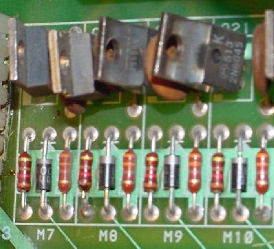
Lamp driver SCRs (Silicon
Controlled Rectifiers) 2N5060 &
T106's on the CPU board.
|
The larger T106 Lamp driver SCRs.
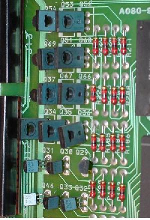
|
Shorting the Coil Voltage to a Lamp Socket.
One very common problem with the 6803 lamp system is shorting a
lamp to the high voltage solenoid power. This unfortunately is way
easy to do, thanks to the position of some of the lamp sockets in
relation to the coils (note the picture below).
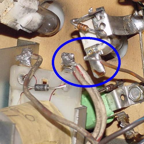
A lamp socket wire lug dangerously close to a solenoid wire lug on an Eight
Ball Champ.
|
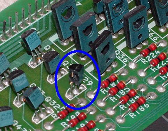
The consequence of shorting a lamp socket to solenoid power is
a blown 2N5060 SCR lamp driver at minimum (note picture below).
This will blow the 2N5060 SCR right apart (the sound of the SCR
exploding can be heard as a distinct "crack").
A blown apart 2N5060 lamp driver SCR. This particular SCR blew up
on an Eight Ball Champ because the playfield lamp socket touched
a drop target coil lug, sending high voltage to the SCR.
|
The 555 sockets used under the playfield on
6803 games for the CPU controlled lamps.
|
3i. When Things Don't Work: Bright Lamps (flash lamps).
Bally used a very unique system for powering the bright lights (aka "flash lamps").
Eight T106 large SCRs control a total of 16 bright lamps. This was different than
say Williams, where a TIP transistor (also used for coil drivers) was needed
to drive a flash lamp. The Bally 6803 system of flash lamps was much more
efficient, as all the TIP driver transistor can be used for high voltage coils
(opposed to 12 volt flash lamps.)
Bally again did something really cool with bright lights. Instead of using 12 volts DC
for the bright lights, they used 20 volts AC
and a center tap transformer.
Why would they do this? Because now they could use the "zero cross" and
use one T106 SCR to drive two completely different bright lamps. Basically they
needed half the number of SCRs to control the same number of bright flash lamps.
If you look at an AC voltage wave form, it's a sine wave. That is, 60 times
a second (60 cycles), the AC (alternating current) goes from +20 volts, to zero volts,
to -20 volts, and so on. And in the process, it "crosses zero volts", hence the term "zero crossing".
If you look at the power supply board, notice fuses FU4 and FU5. These are the two
11 volt AC fuses for the CPU controlled feature and bright lights. Since they come off a center
tap transformer, if you measure their voltage relative to ground, it shows about 11 volts AC.
If you measure their voltage realitive to each other (fuses FU4 and FU5), you get about 20 volts AC.
The center tap transformer allows you to measure these AC voltages relative to ground (which you
usually can't do with AC voltage).
This is important because they use the zero cross, and one T106 SCR can control two completely different bright
lights. Bally calls this "Phase C" and "Phase D" for the bright lights (opposed to phase A and B
for the feature lights). What it means is, they split the AC power into
two phases, and one SCR can control a bright light during "phase C", and a different bright light during "phase D".
The phases are basically the AC signal either above or below zero voltage. Note that the phase C
power wire is black/red, and the phase D power wire is black/blue.
That why if you look at the manual for any of the 6803 games, you'll notice a single T106 SCR
controlling two completely different bright lights. The connector pinout to the different lamps is
actually the same (both bright lights go to the same CPU board SCR and can share the same connector,
though there is some redundance on lamp connectors on the CPU board.) What is different between
the two lamps is the "hot" side - that is one lamp is powered by "phase C" (black/red wire fuse FU4), and the other
is powered by "phase D" (black/blue wire fuse FU5). That's why the 6803 is so picky about these two fuses
working at game bootup (most game's flash codes check for voltage coming through fuses FU4 and FU5,
and will halt bootup if one or both fuses is bad.)
Because of the zero cross functionality on the 6803 system, all bright lights do
use a 1n4004 diode. This prevents back feed of voltage, allowing the zero cross to work.
If a diode does short (doesn't happen too often), it will effect both bright lights controlled by
the single SCR in question. Just keep that in mind.
Remember the large T106 SCRs are used exclussively for the "bright lights" (the flash lamps.)
The bright lights use eight T106 SCRs for a total of 16 individual flash lamps.
Testing Bright Lights.
The only way to test the bright lights is to use the "Single Lamp" test. That is, the
"All Lamps" test does not pulse the bright lights. The bright lights will be shown with a "BR"
designation on the score display before the lamp name, signifying it's a bright light.
I wish there was an "all flash lamp" test, but this was not implemented in the 6803 diagnostics.
The 912 Flash Bulb.
Bally used exclussively #912 flash lamps (opposed to #906 for most other manufacturers).
There are no #89 style lamp sockets in the 6803 games (unless someone changed a lamp socket to that type.)
The #912 is brighter than a 906, but mostly it's also more robust. If you use #906 bulbs in a 6803
game, they will not last nearly as long as the 912 bulbs. For this reason I highly recommend staying
with 912 flash bulbs.
LEDs for the Bright Lights.
You can use 12 volt flash LEDs in Bally 6803 games. There is no modification or
even downside to doing this. In fact, I encourage it. Most LED flash bulbs are
sold as 906 equivalents - this is fine, and they will work in the 6803 system.
3j. When Things Don't Work: the Switch Matrix.
Bally used a standard switch matrix, just like their -35 system utilized.
That means there's 8 switch rows (i0 to i7) and six switch columns (st0 to st5).
This game 6803 games a total of 48 switches (less than Williams and their 8x8 switch matrix.)
Note most 6803 games don't use the last switch column (ST-5), so most games only
use 40 switches. All switches use a 1n4148 diode for isolation.
Some switches use a .05 mfd 25 volt capacitor between the banded diode switch lug and the row
connection. This was done (like on the -35 games) to increase the switch closure time,
so that the CPU scanning would not miss any switch closures. The capacitor is only used
on some switches (check the schematics). Mostly stand up and rollover style switches
use a capacitor (switches that get a real quick switch closure during game play.)
Stuck Switches.
Use the internal test #94 (stuck switches) to find switches that are stuck.
Be aware that some playfield switches have capacitors mounted between the
banded diode lug and one of the wire switch lugs. Often these capacitors
short internally, causing a stuck switch. While in stuck switch test #94,
cut one end of the capacitor to see if the stuck switch clears. If it does,
the capacitor can be replaced, or left off.
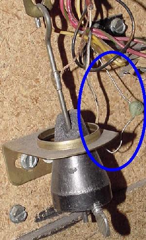
A cut switch capacitor on a rollover switch on Eight Ball Champ. This
capacitor was shorted, making this switch show as "stuck" in the #94
stuck switch test.
|
Note one of the problems with the stuck switch test on early 6803 games is
the switch test will not allow the testing of other switch numbers
*higher* than the stuck switch number, until the lower stuck switch number
is fixed.
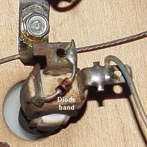
If the 6803 game stays stuck in tilt mode, it could be the
plumb-bob tilt capacitor is shorted! Cut the old cap out to fix this
problem.
|
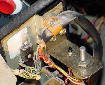
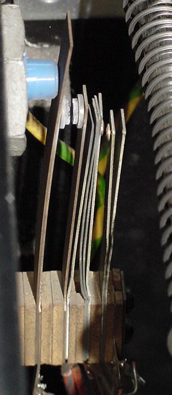
Flipper Lane Change Switch.
The flipper lane change switch is mounted on the same switch stack
as the high voltage tungston flipper coil switch. These two switches are
only by two pieces of insulating "fish paper". If the high
voltage flipper coil switch shorts to the flipper lane change switch,
this will send high voltage down the switch matrix, frying components
on the CPU board. So always check this switch and the fish paper to
make sure the insulator is in good condition.
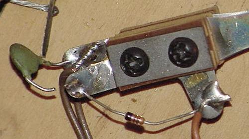
The high voltage flipper coil switch (left) and the low voltage
lane change switch matrix switch (right) on the inside of the
cabinet on an Eight Ball Champ. Notice the gold contacts on
the lane change switch, and the big gnarly tungsten contacts
on the flipper coil switch.
|
Unused Switch Columns.
Depending on the game, some switch matrix "strobes" (columns) are not used.
This is fine, but the CPU board may not be jumpered to use the a particular
column. This can be an issue if the CPU board is moved from a game not using
strobe 5, to a game that does use ST5.
For example, Bob E. describes this exact problem in his Blackwater 100.
After buying the game, none of the switches worked in strobe (column) five.
The problem was fixed by installing CPU board jumper JW9 and removing
jumper JW8. The Blackwater 100 manual generically listed these CPU board jumpers:
In = JW2, JW4, JW6, JW9, JW10,
Out = JW1, JW3, JW5, JW7, JW8, JW11.
Clive explains that the Wn jumpers connect the PBnn strobe to the
anode of the strobe line blocking diode. This anode is also tied
to +5v to provide the drive current for the switch matrix line.
Leaving the jumper out isolates the diode
(and strobe line in it's entirety) from the PIA but leaves current drive
to the matrix enabled via the pull-up. Bally generally left the W9
jumper in even though there were no switches
on that line in some games (Escape from the Lost World being a prime
example). Removing the resistor has no affect if W9 is out since the
circuit is totally isolated. If strobe 5 is required to drive some switches
then the resistor jumper needs to be in to provide enough drive current (the port
cannot supply enough current needed and it will strain the PIA output
drive possibly causing it to fail).
3k. When Things Don't Work: Ball Trough Infrared Optic Switches.
Starting with Dungeons & Dragons and Blackwater 100, Bally used opto switches in the
ball trough instead of mechanical switches.
Flaky optos in this style of ball trough are very common. The game
won't start if all the balls needed can not be accounted for,
so the ball trough optos are very important. Also sometimes the
game will start, but two or even three balls will stack up in
the shooter lane at the start or during game play.
Bad solder joints and bad 68 ohm resistors on the trough boards are very common.
Reflow the solder joints on these boards is a good idea, and check the
resistors for 68 ohms.
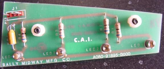
Trough opto switch board from Blackwater 100. This is the "transmitter" board
with the light emitting LEDs. Picture by Bart.
|
Replacement Optos and Opto Installation Warning.
It's also a good idea to have some spare opto emitters and receivers (detectors)
These are the metal-can type, a TO-18 style transistor package
with a lens on the top.
The emitters are part# MLED930 (which crosses to an NTE 3028) and the
detectors are part# MRD370 (which crosses to an NTE 3036). The only
thing to beware of is the that the NTE emitters are
polarized the *opposite* from the original parts.
So to use the NTE replacements, mount them with the
little metal tab in the *opposite* position to what
is shown on the silk-screened PCB.
Trough opto switch board from Blackwater 100. This is the "receiver" board.
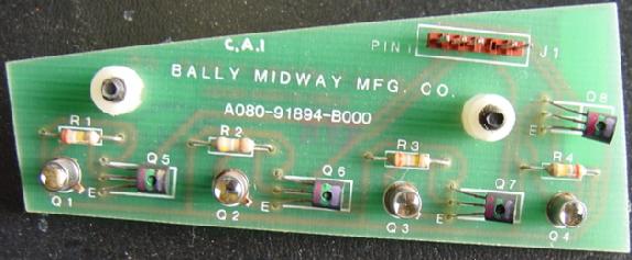
|
If just one opto is needed,
the first opto in each board can be robbed, as it only uses the last
three of the four optos. But watch out, they numbered these optos backwards
to what one may think! The #1 opto is the one that is not used, and
#4 is the one closest to the plunger (for ball #1).
Trough opto switch boards mounted in a Blackwater 100. Picture by Bart.
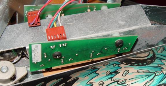
|
The optos in Dungeons & Dragons and Blackwater 100 are difficult to work on.
It is best to prop
up the playfield on the prop bracket, remove the third playfield (take
three closest screws out of the left ramp that delivers balls so
it can be flexed aside, remove the four screws that hold the third
playfield down, undo the two large Molex conectors that provide power
to the flipper/lamps/switches, and the two small Molex
connectors that connect the trough circuit boards). Then
lift the third playfield off the game. Now unscrew the two trough-opto
circuit boards from the trough metal and then re-install the
third playfield, just laying it there on the brackets. Connect the
two large Molex plugs, then connect the trough opto and LED
boards back up while they are dangling out the front. Now
test each opto, and each LED (use a Radio Shack LED detector card,
a camcorder or digital camera, that way the opto emitters can be seen).
Ball trough on a Bally Truck Stop. This picture is taken from another
angle, and it shows how the ball closest to the shooter lane does not have
an optic switch (or a mechanical switch either.) Truck Stop is a 3-ball game,
and only two balls closest to the outhole have optic switches. The other
two optics on the LED board, are not used (and are not wired into the
switch matrix either.) Hence they are good parts donors for the two
implemented optic switches.
Blackwater only uses the three optos closest to the shooter, the fourth
one is not used. Watch out, the numbers are confusing! The silk-
screening on the PCB says Q1 for the unused opto,
Q2 is really the first switch (identified as "left" in the switch
matrix), Q3 is switch two (middle) and Q4 is the switch three, (right)
the one closest to the shooter.
So, going from the opto closest to the shooter lane, the transistor is
identified as Q4, but it is Switch three in the matrix. The next one to the
left is Q3, but is Switch two in the matrix. The third one is Q2, but
Switch one in the matrix, the fourth (farthest left) one is Q1 and is not
used! The LED's are numbered similarly.
Before replacing optos and emitters, check for flaky solder-job on the
68 ohm resistors on the board. I think I may experiment with putting some
rubber grommets under the mounts or something, to try and counter the
vibrations and shocks they may be experiencing.
Dave Wagler has said that he has had good luck putting a dab of RTV silicone
behind the optos when mounting to the boards. Also, Tuuka
suggests that the lights from the "R-A-I-N" targets can confuse the
optos, so put some cardboard or duct tape over the metal trough walls to
obscure them from the lights.
Also Instead of reflowing solder,
suck the old solder off, cleaned up the pads
(single-sided boards...no plated-through holes) and resoldered.
Test the Optics.
Radio Shack sells a $5 credit card sized "infrared sensor".
MCM Electronics also sells one, #72-6771, for about $7
(800-543-4330 or www.mcmelectronics.com).
If you put this card right in front of an opto transmitter,
the opto's emitting light can be seen; the light will show on the colored
band of the sensor card. Also, a digital camera or a camcorder
will usually show infrared light from the transmitting opto,
if the digital camera has a small LCD screen
used to show images "live" (but personally I like using the
opto cards better).
Using a Radio Shack or MCM
infrared detector card (or a digital video or digital still camera),
check all the transmitter LED infrared optos to see if they are working.
Message seen on the score display while testing the ball trough optics.
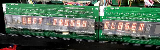
After that is done, block the LED transmitters with some black electrical
tape. Then shine a small pocket flashlight into each of the
receiver board detector optos. They should register in the switch test
(room needs to be somewhat dim for this; ambient room light can
also activate these).
Ball trough on a Bally Truck Stop. This is a three ball game,
and ball #1 (right most ball) does not use an optic. So only
the right two optics are used. Hence if one of the transmitter optics is
bad (common), the left most opto can be stolen without ill-effect.
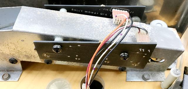
Replacement for the MLED930.
The MLED930 infrared transmitter is a bit hard to find, and generally
a bit expensive. But the good news is, the later Williams infrared LEDs
(as used on the ball trough for Williams/Bally WPC games Indiana Jones
and later) can be substituted. Of course you must install this style
of LED correctly. See the picture below, but basically the flat side
of the LED needs to be opposite of the "tit", which is silk screened
on the LED circuit board.
Ball trough on a Bally Truck Stop. The stock MLED930 has been
replaced with modern style WPC infrared LED.
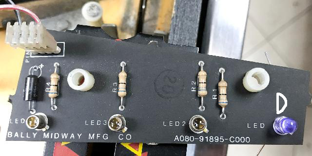
Another LED test method.
To verify that a particular transmitter is working (and to verify that
that receiver is working too), try this... Remove the balls from the
game and get into diagnostic
switch test. Then remove the two screws holding
the transmitter board. Angle the board so that a known working LED transmitter in question
is pointed towards the receiver you wish to test. Move the board in and out
of range, and the switch test should show the optic switch triggering.
Likewise if you wish to test a tranmitter, do the same test, but angle
the transmitter board to use
the transmitter in question, against a known working receiver.
Ball trough on a Bally Truck Stop, and testing a transmitter LED
on a known working receiver LED. This is a good test to make sure
the issue is either the transmitter (most common) versus the receiver.
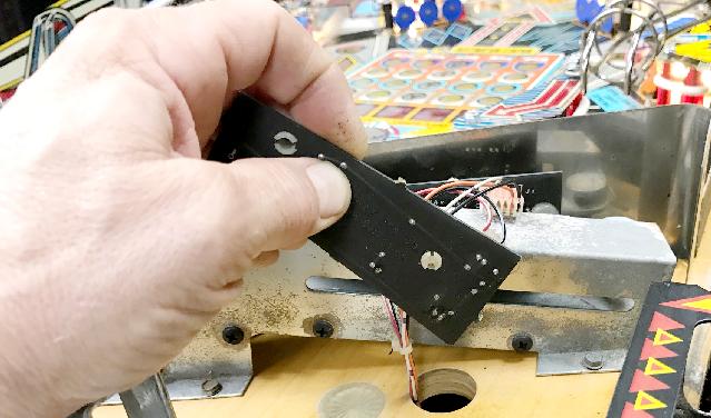
3L. When Things Don't Work: Score Displays.
Displays: show garbage every once in a while.
Pulling the connectors off the back of the displays and
pushing them in a few times always cleared that one.
7-digit display driver board. Note all discrete components (no
expensive UDN7180 chips here!)
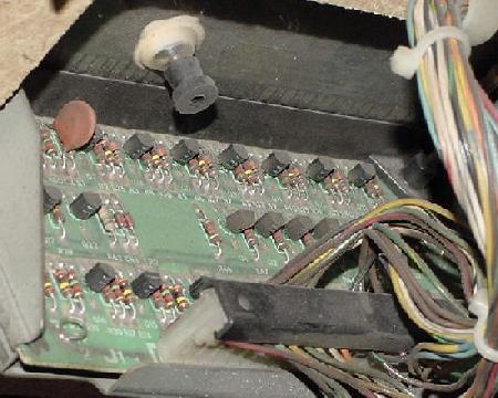
|
The Bally 9 segment, 14 digit NOS score display as used on many 6803 games.
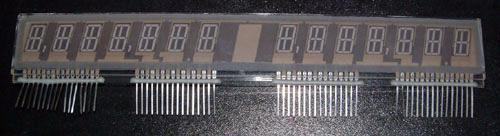
|
3m. When Things Don't Work: Problems with Flippers.
Flipper Coil.
The flipper coil used in most 6803 games is
Bally part number AC70-00026-0000, which
when translated is A-24-570/34-3600.
Double EOS Switches.
Bally used a unique system of EOS switches in their games with more than
two flippers. For example, on Eight Ball Champ (which has three flippers),
the lower right flipper has two EOS switch. One EOS switch is Normally-Open (NO),
and the other is Normally-Closed (NC). The normally-closed EOS switch
acts just like a standard EOS switch for the lower flipper.
But the second normally-open EOS switch is connected to the upper flipper.
The high power portion of the upper flipper coil does energize
until the lower flipper has completed it's "flip", and closes the normally-open
second EOS switch. In other words, if the lower flipper doesn't flip,
the upper flipper won't energize either! This unique system on the 6803 can
cause quite a bit of confusion, since is it different than the flipper
systems used by othre manufacturers.
The benefit to the system is that there is only one cabinet flipper
switch for both the upper and lower flippers. And the
upper flipper isn't in the power stroke phase until *after* the lower flipper
coil's initial power phase is off. This saves current draw and
perhaps a noticeable voltage drop at the transformer.
The first generation flipper used on 6803 games. Note the double EOS switch.
This double EOS is used on lower flippers when there is an associated upper flipper.
The normally-closed EOS switch acts just like a standard EOS switch. But the
normally-open EOS switch is connected to the upper flipper. The upper flipper does
not energize until the lower flipper has completed it's "flip".
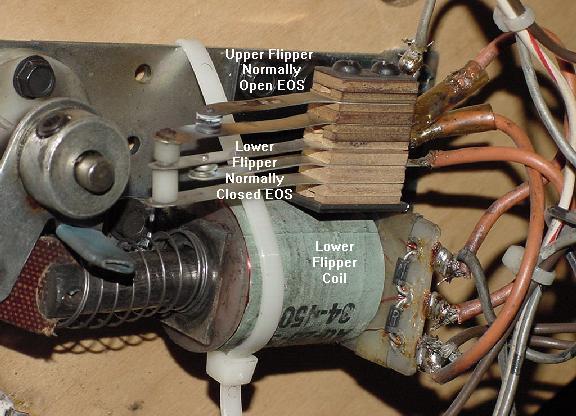
|
3n. When Things Don't Work: Sound Problems.
DAC 7533 Failures on Sound Boards.
Bally put out a service bulletin that they were having
problems with the 7533 DAC (digital to analog converter)
chip on many of their sound board (including the Turbo Cheap Squeak TCS
and the Sounds Deluxe board, used exclusively on the 6803 series of games.)
As the game is powered down and the +5 volts falls,
a 47 mfd cap attached to pin 1 of the DAC goes higher
than the +5 volt line. This causes the DAC chip to fail.
The solution is to remove this capacitor from pin 1 of the DAC.
This eliminates the transient condition on the DAC chip.
Note the position of this cap is different, depending
on the exact sound board used (see table below.)
| Pinball Board | Series | Board Name | Remove Cap |
| A084-9 | 1855 | TCS Turbo Cheap Squeak (Pinball) | C30 |
| A084-9 | 1864 | Sounds Deluxe (Pinball) | C12 |
And this applies to the following Bally 6803 pinball games:
- Black Be1t (TCS)
- City Slicker (TCS)
- Dungeons & Dragons (Sounds Deluxe)
- Escape from the Lost World (Sounds Deluse)
- Hardbody (TCS)
- Heavy Metal (Sound Deluxe)
- Motordome (TCS)
- Party Animal (Sounds Deluxe)
- Special Force (Sounds Deluxe)
- Strange Science (TCS)
Here's the original service bulletin from Bally in PDF format.
Squawk and Talk Sound Board.
Squawk & Talk sound board often has bad background and speech
sound pots. A084-91864 Sounds Deluxe board's main weakness is the pot (cheap)
and the 10 bit DAC (U8-7533), which is prone to static/electrical failure.
6809 Sound Board LED Tests.
- 1st flash - Validate U7 program ROM.
- 2nd flash - Validate U6 RAM.
- 3rd flash - Check U8 PIA (6821).
Sounds Deluxe 68000 Board LED Tests.
- 1st flash - Validate U11 program ROM.
- 2nd flash - Validate U12 program ROM.
- 3rd flash - Validate U13 program ROM.
- 4th flash - Validate U14 program ROM.
- 5th flash - Check RAM U9,U10.
- 6th flash - Check PIA U7.
The Squawk & Talk sound board's crappy background sound and speech
volume pots.
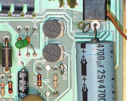
|
Squawk and Talk LED Flashes.
First Flicker.
Fakers Guide: No flicker means a bad U5, flakey U15, leaky C1, open R1,
leaky CR1, or bad U17.
Techno Guide: On power up, U1 requires +5 volts to be applied before the reset
line is allowed to go high. If this condition is met, the LED
does a quick "flicker". At power-on, C1 slowly charges via R1. The
voltage across C1 is monitored by U15. When it reaches 1.7 volts DC,
U15 take the reset line high. Diode CR1 across R1 provides a
quick discharge path for C1 in the event the +5 momentarily
disappears.
First Flash.
Fakers Guide: No first flash means a bad U6, U15 or U17.
Techno Guide: The U1 chip tests the U6 RAM. It attempts
to write then read back all 256 patterns in each of the 128 scratch
pad RAM memory locations. If U1 completes the 256 x 128 = 32,768 tests,
the LED is flashed.
Second Flash.
Fakers Guide: No second flash means PIA U7 is bad.
Techno Guide: The U1 chip now tests the first PIA U7. Each
of the two PIA chips U7 and U11 are interchangable. The test
is the same for both. If it determines the two PIAs are good,
the U1 chip performs some test. This includes testing each of
the two full byte port initialization registers, testing the two
full byte I/O registers, and testing the CA2 and CB2 ports.
If all checks out, the LED is flashed.
Third Flash.
Fakers Guide: No third flash means PIA U11 is bad.
Techno Guide: The same test above is performed on PIA U11.
Fourth Flash.
Fakers Guide: No fourth flash means sound generator U12 is bad.
Techno Guide: The U1 chip performs a test on the
sound generator chip U12. The U12 chip is controlled by
PIA U11. If the sound chip passes the LED is flashed the
fourth time. A bad PIA at U11 can also cause no fourth flash!
Or a bad connection between the three chips U1 (microproocessor),
U7 (PIA), and U12 (sound generator).
Fifth Flash.
Fakers Guide: No fifth flash means speech chip U8 is bad.
Techno Guide: The speech generator U8 chip requires
an initialization sequence at power-on. Since the chip
is a "slow" device, there is an acknowledgement signal from
the speech chip to the U7 PIA. Every time a write to the
speech chip is done, the speech chip acknowledges. The U7 PIA
attempts to send 9 bytes of initialization data to the speech
chip, one at a time, waiting for acknowledgement. If it is
sucessful, the speech chip is considered functional and the
LED is flashed the fifth time. A bad PIA at U7 can also cause
no fifth flash! Or a bad connection between the three chips U1 (microproocessor),
U7 (PIA), and U8 (speech chip).
System11 Sound board used on Truck Stop/Atlantis.
When Williams bought Bally in 1987, there were some games in design
that Williams released at 6803 games. Truck Stop and Atlantis were
the two that ended up as a Bally 6803, but with some Williams parts.
One thing that was changed on these two games was the sound board.
Instead of using a Bally sound board, a standard Williams system11 sound board
was incorporated into the Bally 6803 system. Note these two games boot with
the familiar Williams "bong" sound (unlike earlier Bally 6803 games.) This is
because of the system11 sound board.
In order to make the system11 sound board mate with the Bally 6803 system,
a small interface board was used. Basically it took the sound signals
from the Bally 6803 MPU board, modified them a touch, and outputed them
through a ribbon cable to the Williams system11 sound board.
The sound interface board used on Truck Stop and Atlantis to
allow the Bally 6803 MPU board to talk to a Williams system11 sound board.
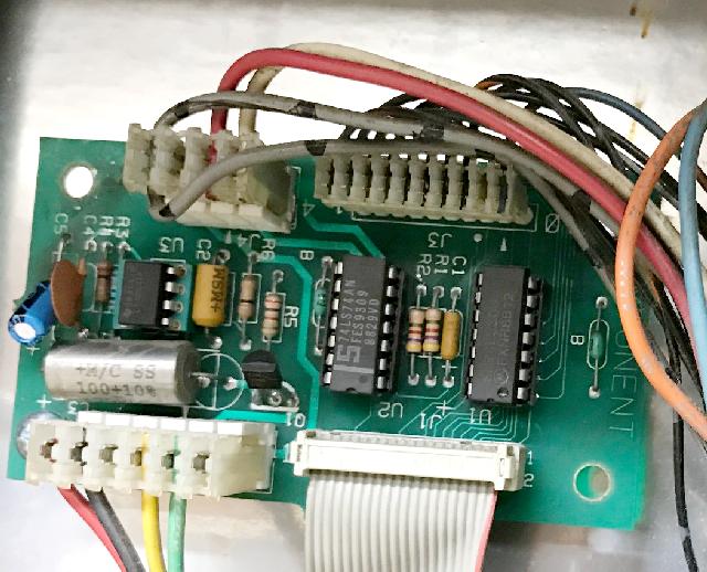
Note the System11 sound board is a pretty standard Williams part, using
three 27256 EPROMs for the sound files. But note that Williams also used
this nearly identical sound board on some of their video games too. So if
you have a sound board problem, you can steal the board from the 1990 Williams video
game "high Impact" for example, and use it in a Williams system11 or Bally
6803 game. The only modification needed is to "quad up" the EPROM files
to take the stock 27256 EPROM files to a 27010 EPROM. This is done using
a computer and the MS-DOS copy command (with the /b option) as follows:
copy /b file1.256 + file1.256 + file1.256 + file1.256 file1.010
1990 Williams video game "high impact" sound board used on a Bally
Truck Stop game, with modified 27010 EPROMs installed.
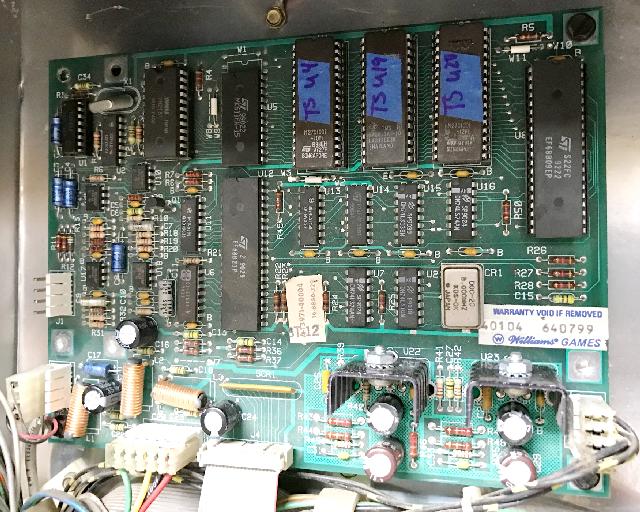
If you would like to test this theory, you can actually plug in the
"high impact" sound board in a Bally 6803 game (complete with the
high impact ROM files), and hear the boot up Williams "bong".
3o. When Things Don't Work: Game Specific & Miscellaneous Repair Tips.
Problem: I have a Dungeons & Dragons/Blackwater 100, and when the start
button is pushed it displays, "ball missing", yet there are three
balls installed in the game. Or sometimes the
game will start, but two or even three balls will stack up in
the shooter lane at the start or during game play.
Answer: This is a known problem on Dungeons & Dragons and Blackwater 100.
What happens, is that
the opto detectors in ball trough get extra light from the Blackwater RAIN feature
lights, and then think the ball isn't there even though it is, giving the
"ball missing" error.
To fix, remove bottom arch plate, and cover the ball trough
with black cardboard or something else non transparent. Secure
with tape.
Also verify, using the game's switch test, that all the trough
opto receiver switches are working. And when replacing these optos,
put a dap of silicon behind the opto receiver and/or transmitter,
and mount the opto off the board just slightly. This will prevent
vibration from breaking the opto in the future.
Problem: I have a Blackwater 100
and I've been trying to change the game to the 3-ball version (the game
can play either 1 ball or 3 balls at game start; there are two different ROM
software sets for BW100.) However the two sets of ROMs both produce the same problem:
the machine kicks out four balls at game start instead of three, then never starts
play. The machine and all the switches work fine, as
it plays fine with the one ball ROMs, and all switches test fine in
diagnostics. I've even taken the trough opto boards out and tested them,
and everything is in order. What is the problem?
Answer: Running the switch test often shows the trough and other
switches as working 99% of the time, but once in game
is started the machine acts up 99% of the time. The best fix is to get the GLM repro
trough opto boards, as this solves these problems
(a href='http://www.greatlakesmodular.com/products/pinball/6803tbs.html'>GLM boards.)
Bally really messed things up with the trough on this game, and it's
rather confusing to work with.
Even though it's only a three ball game, four balls are required in the trough.
Usually the trough is numbered from right to left on 6803 games, but on BW100
it's a bit different.
Starting from the right, the first ball doesn't have a switch.
Then the next ball is ball #3 in the switch test, but opto #4 on the PCB.
The next ball is ball #2 in the switch test, but opto #3 on the PCB.
The last ball is ball #1 in the switch test, and opto #2 on the PCB.
Finally there is a last opto #1 on the board that is not blocked by any
of the balls in the trough, and is unused.
So why does the game work for one ball play and not three ball play?
What happens is that for three ball play, the game puts three balls in the starting
gate at the top of the playfield, and leave one ball in the trough.
That one ball that's left in the trough doesn't have a switch. If ANY of the other three trough optos
show a momentary closure (due to flakey optos), the game thinks there are two balls
still in the trough, and automatically kicks out the fourth ball.
During one ball play there is only one ball in the shooter lane,
so as long as opto #2 (the left most ball in the trough switch #1) is acting fine,
then the game will act normally for one ball play.
So if the game works in one ball play but not for three ball, this is a symptom
that opto pair #3 or #4 is bad or intermittent.
A trick is, since opto #1 is unused, try swapping opto #1 with either #3 or #4
to see if that fixes the switch issue.
|
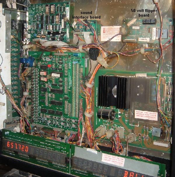
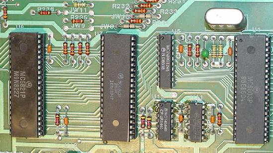
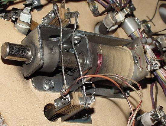
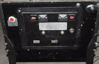
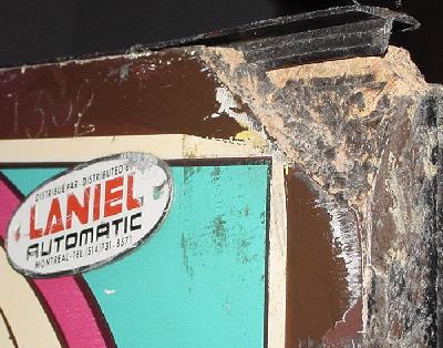

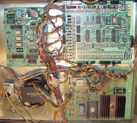

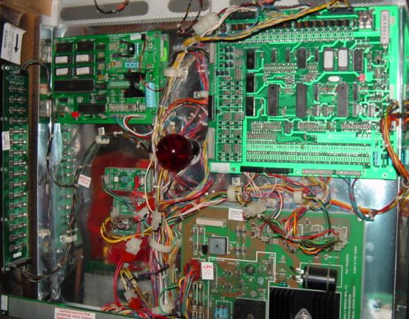
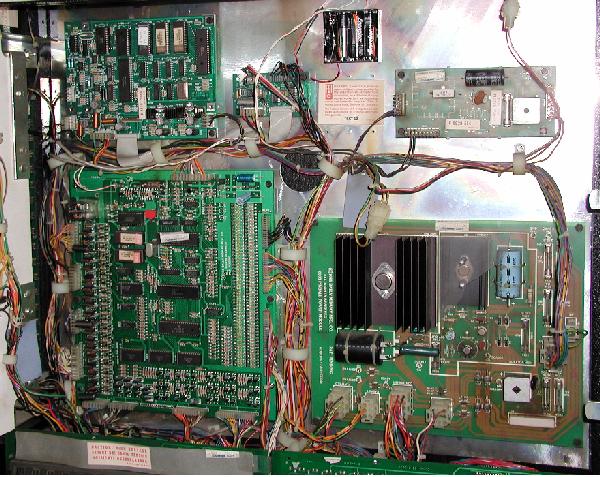
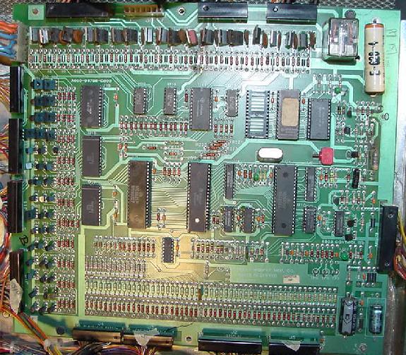
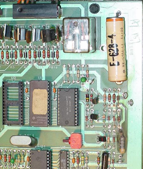
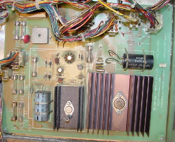
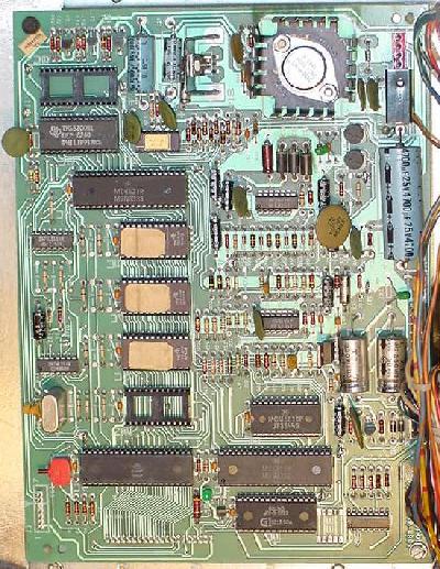
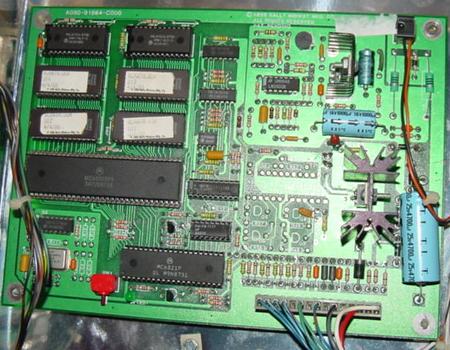
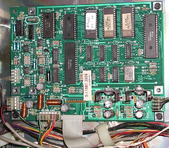

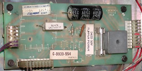
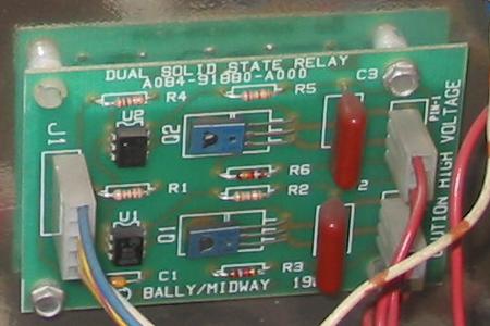
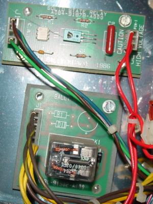
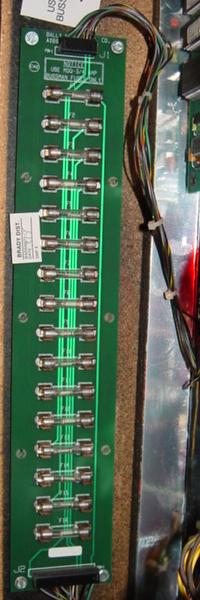
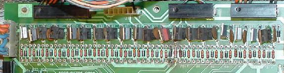
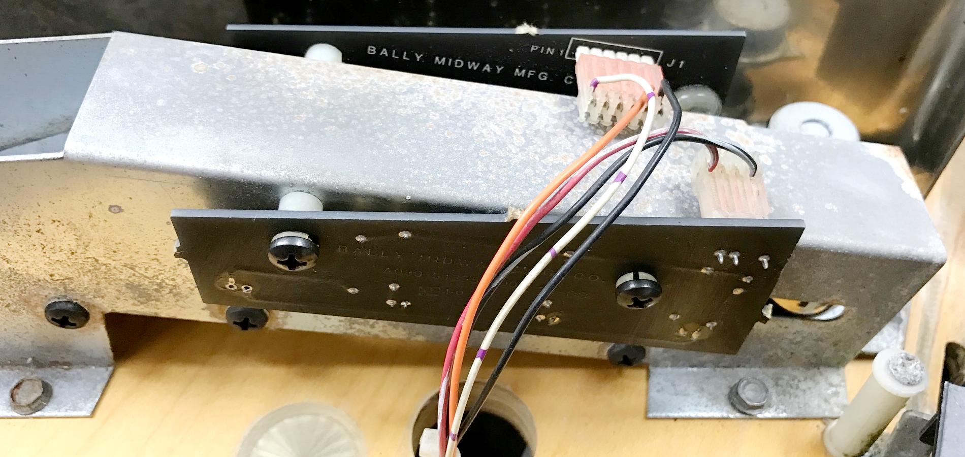

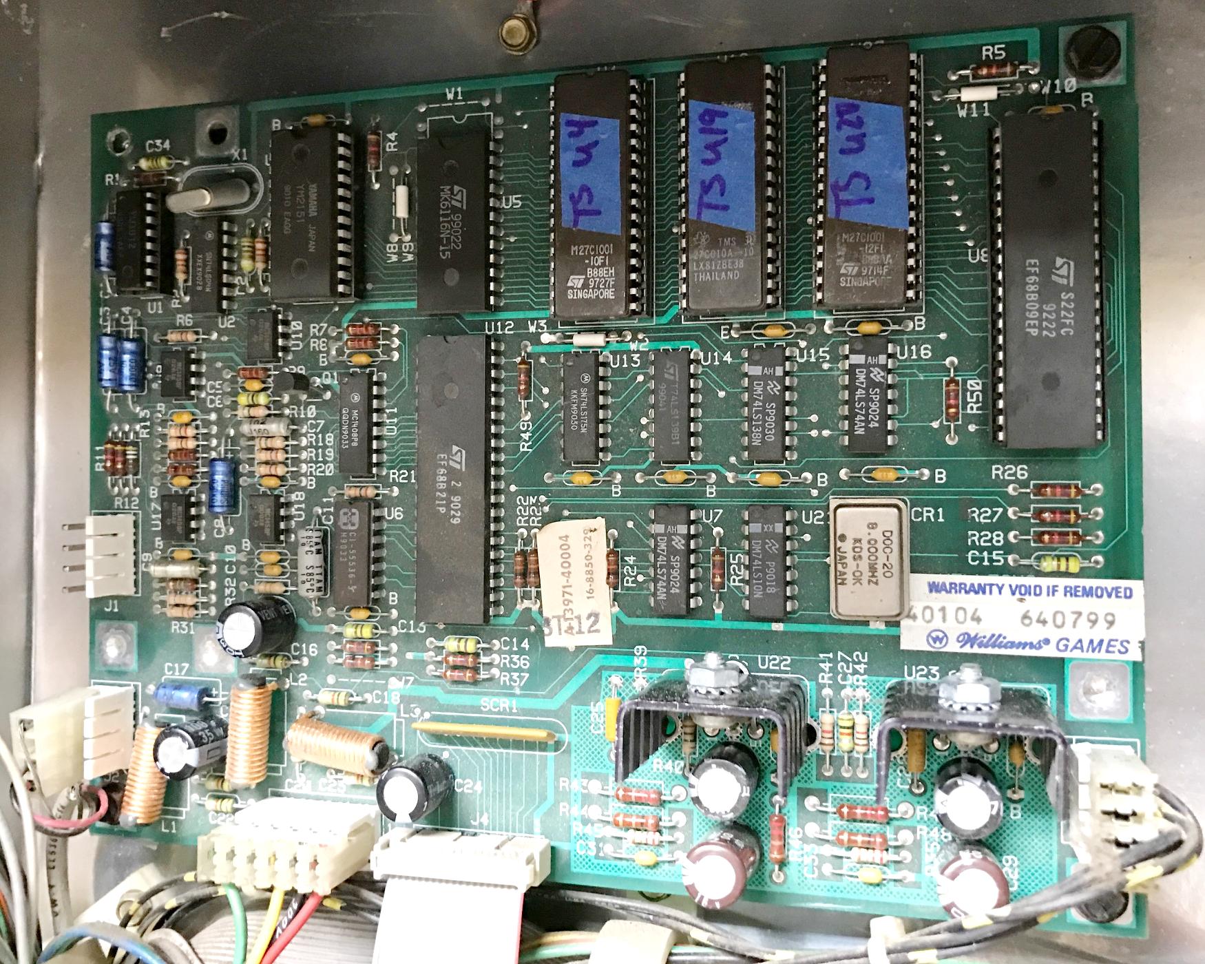
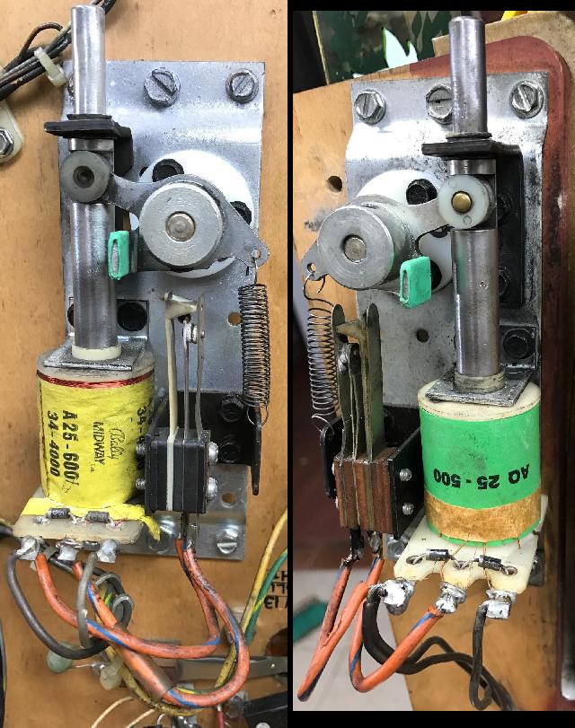
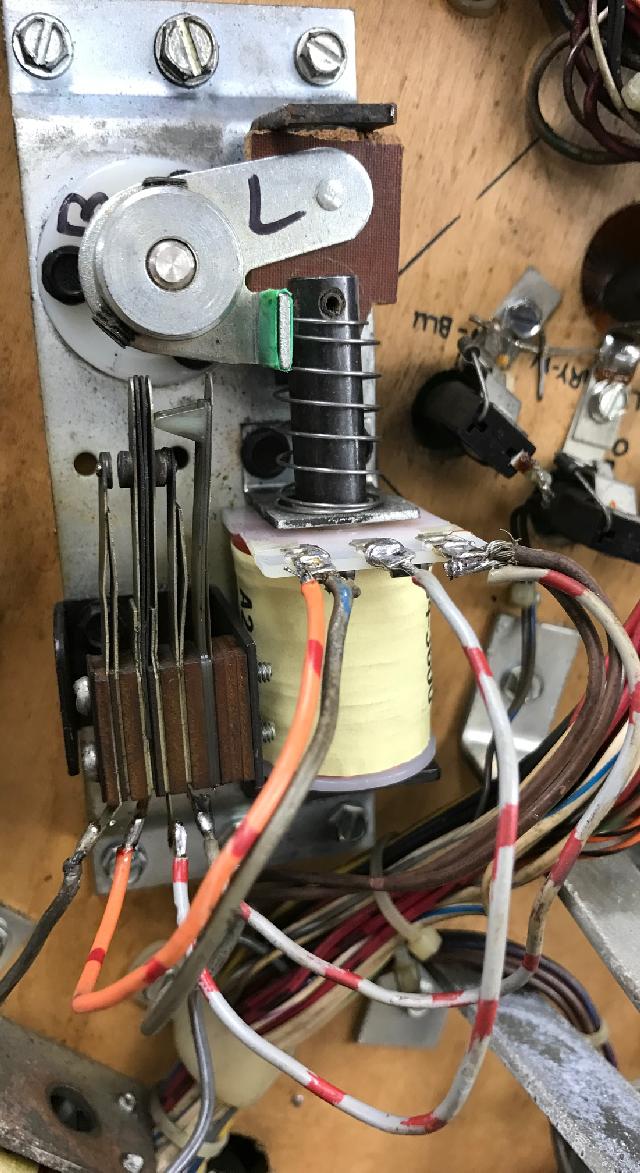
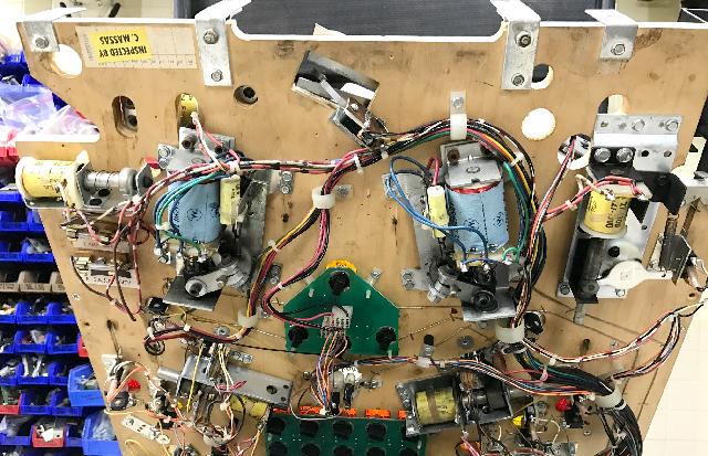
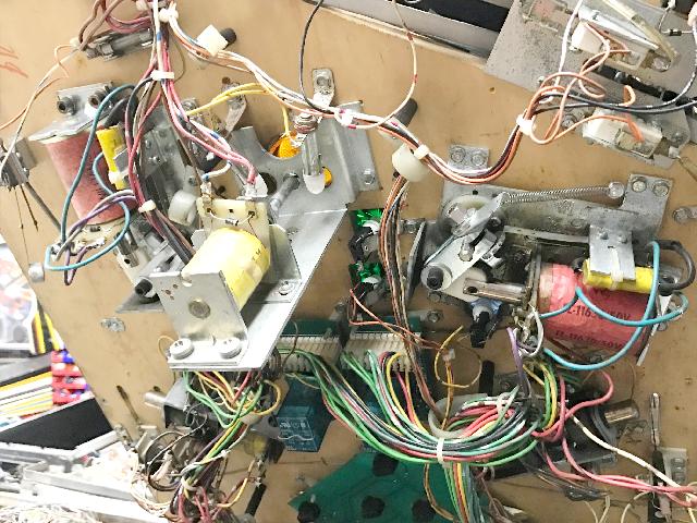
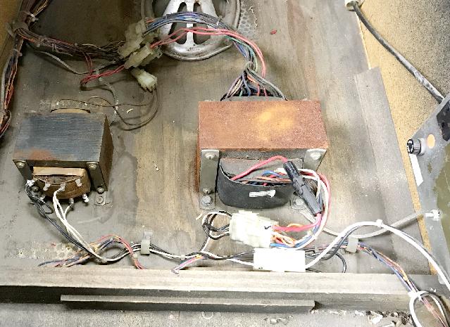
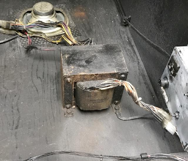
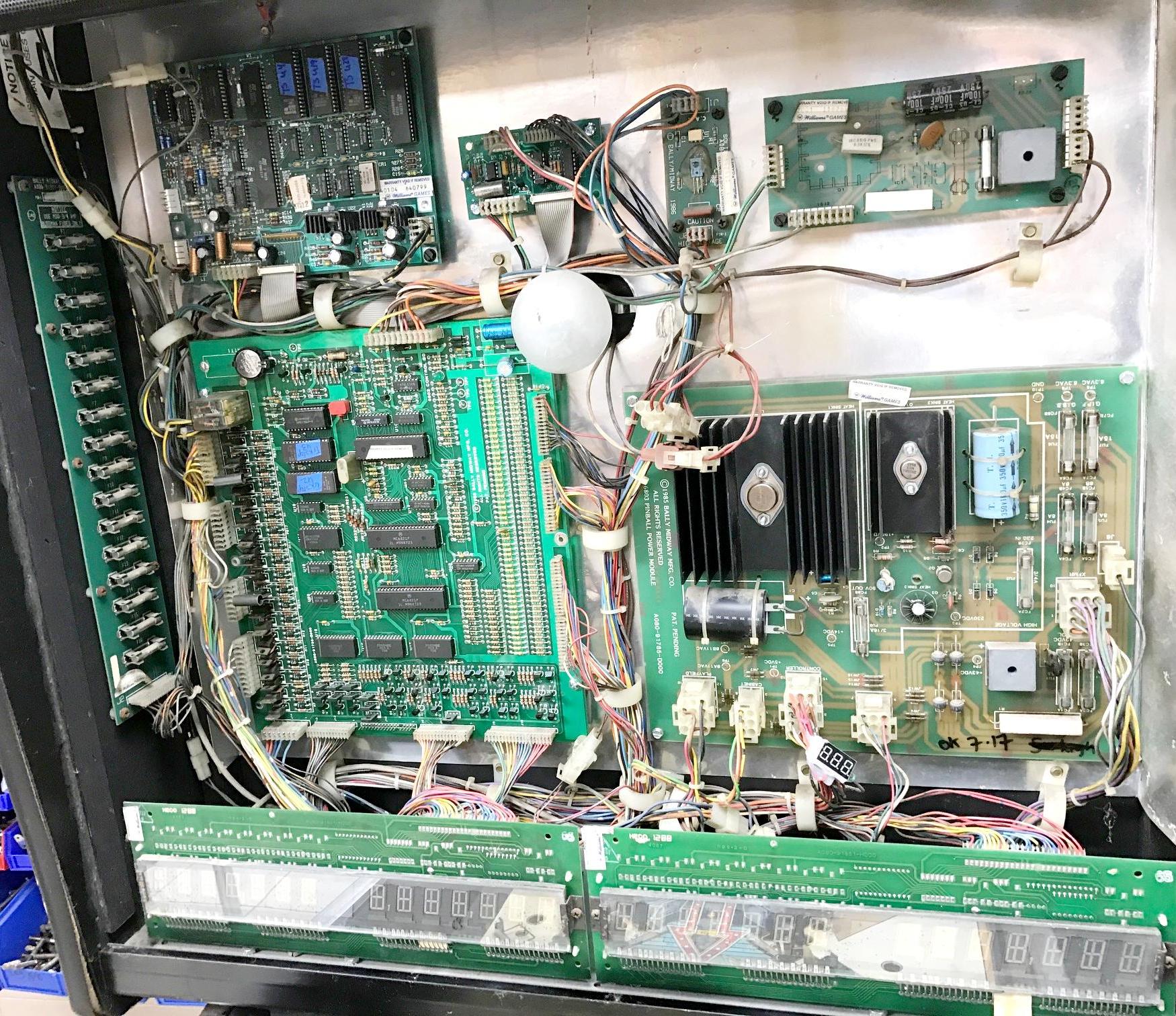
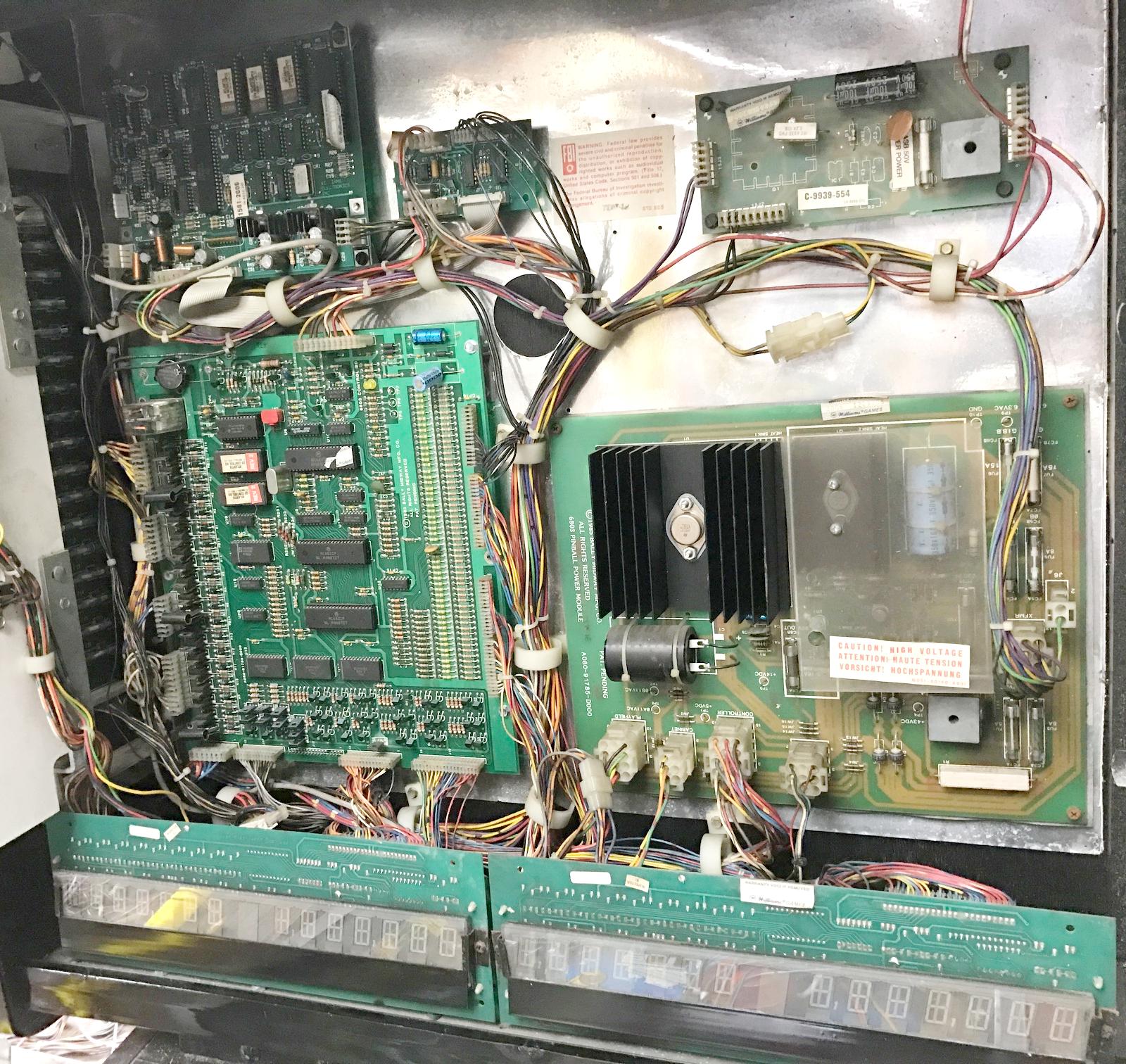
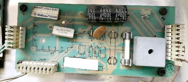
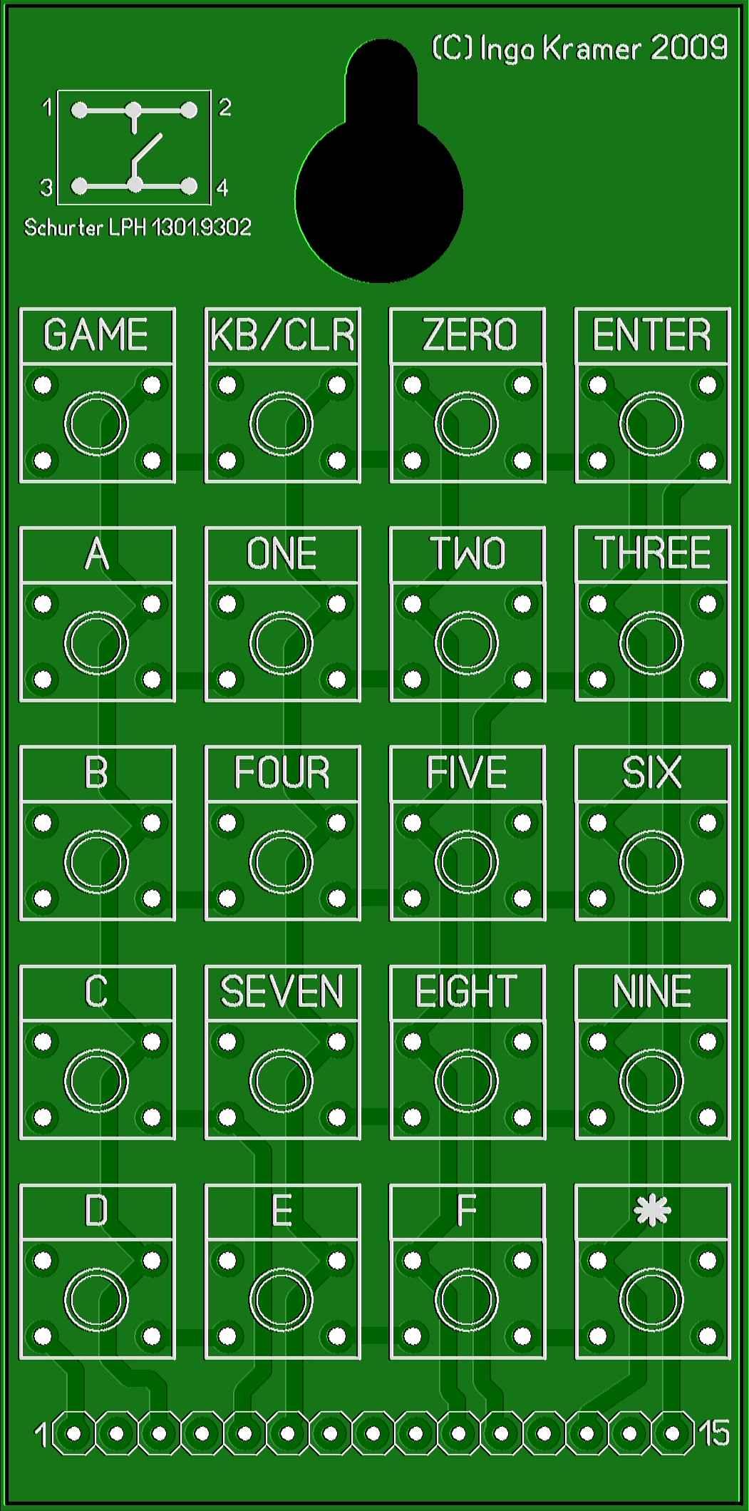