3a. The Mechanics: Rebuilding EM Pinball Flippers
Flippers are the interface between you and the game. Having good strong flippers
is mandatory. The parts that are in the game are probably 25 years old or older.
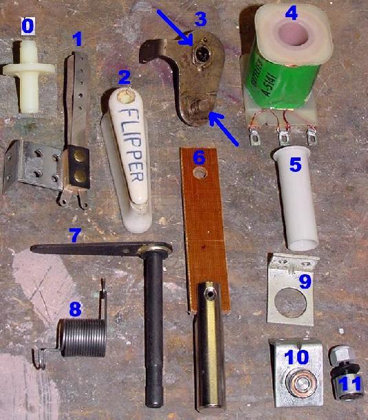
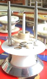
Here's the parts needed for flipper repair. One of each part is needed for each flipper.
- Mandatory: Nylon flipper coil sleeve - if this sleeve can not be removed from the
original flipper coil, then a new flipper coil is also needed. Gottlieb
part #A-5064 (1 21/32") or A-5065 (1 7/8"). #5 pictured below.
- Mandatory: Nylon thru-the-playfield flipper bushing. Gottlieb part #A-2408.
#0 pictured below.
- Mandatory: plunger and bakelite link. These are usually sold together,
if bought from the Pinball Resource. I don't suggest trying to assembly
the plunger/link yourself. Gottlieb part #A-3396 (game dependent). #6 pictured below.
- Often needed: flipper pawl return spring (there are often separate right and left
side versions). Gottlieb part #A-3328 (left), A-3329 (right). #8 pictured below.
- Often needed: EOS switch. #1 pictured below.
- Sometimes needed: flipper pawl (specify right or left side). For Gottlieb,
it is best to use the "old style" pawl (more explained on that below).
Gottlieb part #A-5982/A-5983 or A-3399/A-3400. #3 pictured below (old style).
- Sometimes needed: flipper shaft. Gottlieb part #A-6888. #7 pictured below.
- Sometimes needed: plastic flipper bat (the part the ball hits).
Gottlieb part #A-5095 or A-5394 or A-5393. #2 pictured below.
- Sometimes needed: flipper coil. Gottlieb part #A-5141. #4 pictured below.
- Rarely needed: upper flipper coil mounting bracket. Gottlieb part #A-5147.
#9 pictured below.
- Optional: Coil stop. Gottlieb part #A-5189. #10 pictured below.
Also available, just the core of the coil stop and aluminum nut,
without the mounting bracket. Gottlieb part #A-4862. #11 pictured below.
Gottlieb flipper rebuild parts.
If you are keeping the same flipper coil, replace the flipper
coil's nylon sleeve (a thirty cent part). Also always replace
the metal plunger and link with a new one. Often the plunger link
is metal - the replacement should be bakelite (a brown fiber-ish plastic),
which will wear better and is lighter weight (for better flipper performance).
These new parts will give optimal performance as there won't be any "slop" to
absorb flipper energy.
When rebuilding the flippers, it's not a bad idea to replace the
coil stops. New coil stops will make your flippers quiet when
holding the cabinet flipper button in. Also sometimes the old
coil stops are magnetized enough to hold the flipper in the
up position.
You can buy new stops, or just rotate the flipper
and backbox Replay unit coil stops. The replay unit gets very little use,
so its coil stops should be in excellent condition. Just move
these stops to the flippers, and the flipper stops to the replay unit.
Many EM games have wear marks on the playfield from the flippers.
This is known as "flipper drag". This is caused from worn or cracked nylon
flipper bushings, which go through the playfield. These nylon
flipper bushings should ALWAYS be replaced to stop flipper
drag. New flipper bushings are slightly taller than originals to
prevent this problem.
Also make sure the flipper return spring is not too tight. There should
be enough spring to return the flipper, and no more. Too much return
spring and it is only being fought by the flipper coil. You can adjust
the flipper spring in 1/3 turn increments (by moving the spring's anchoring
position to another of the three screws).
Lastly, make sure the EOS (end of stroke) switch is adjusted correctly.
It should open about 1/8" when the flipper is fully "flipped". Also
file the EOS switch clean with a small metal file.
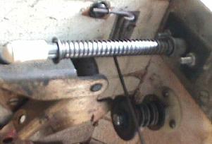
You may also want to install new Gottlieb EM "hi power" flipper coils (as shown
in the above picture). These are available from the
Pinball Resource,
and provide about 10% more power (probably not necessary if you have done
all the above maintainence).
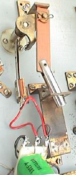
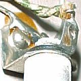
Rebuild the flipper with new
plunger and link. Remove the
coil stop to release the parts.
EM Flipper Rebuild Instructions.
Work on one flipper at a time. This way if there is some issue,
you can always look at the other flipper for comparision. Note
these instructions have 1950s and 1960s Gottlieb flippers in mind,
but apply to most other game makers and eras of EM flippers.
- Put the playfield in the "up" position, leaning it against the backbox.
Find a small step stool to stand on.
- Remove the coil stop (lower bracket) from the flipper coil. This will
allow the removal of the flipper coil (just slide the flipper
coil off the plunger).
- Slide the old coil sleeve out of the flipper coil. If the
coil sleeve will not come out easily (I use a yellow handled nut driver
to push the old sleeve out of the coil), replace the entire coil
(which should come with a new coil sleeve).
- If using the original coil, inspect the three wire lugs. Visually
check the three lugs and make sure the tiny coil winding wires are attached
to the lugs. The center lug (the common lug) should have both a thin and thicker
winding wire attached to it. The other two outside lugs should have a single
winding wire attached to it (one thin, one thicker). If any of these
wires are broken, replace the coil (though sometimes one winding can
be unwound, the wire sanded to remove the insulation, and resoldered
to the solder lug). A multi-meter (DMM) can also be used to check the
coil. With one lead of the DMM on the center common lug, and the other
on the thick wire outside lug, about 4 ohms should be seen. Move the
outside DMM lead to the thin wire lug, and about 100 ohms should be seen.
Note the game wires going to the center flipper coil lug may need to be removed
to get accurate DMM readings.
- On pre-1969 Gottlieb games, remove the spring clip from the
flipper pawl, which holds the
plunger/link to the pawl. The plunger/link can now be remove.
Throw the original away, as a brand new plunger/link should be used.
On 1969 and later Gottlieb games, the flipper pawl is attached to the
plunger's link by a roll pin. This complicates things a bit. See below
for more information*.
- Remove the flipper pawl from the flipper shaft. Usually there
are two allen screws or small 1/4" screws holding the pawl to the
flipper shaft. As the pawl is removed, the flipper spring will
also need to be unwound/removed.
- Remove the flipper/flipper shaft from the top side of the playfield. It should
freely pull out.
- Undo the three screws from under the playfield that hold the
nylon flipper bushing. Note which screw retains the flipper return
spring. Throw the original bushing away, and replace with
a new nylon flipper bushing. The new bushing should stick through
the top of the playfield about 1/8". Re-secure the bushing with
the same three screws, and reattach the flipper return spring on
the same screw.
- Replace the flipper shaft thru the nylon flipper bushing on
the top side of the playfield.
- Replace the flipper pawl onto the flipper shaft. HAND TIGHTEN
the two pawl screws.
- Reattach the flipper return spring on the flipper pawl.
The spring should have enough power to move the flipper back
to the home position, but not too much power. If too much
spring power is used, the flipper coil will just have to
fight the spring, weakening the flipper. Adjust accordingly.
- Attach the new plunger/link on the flipper pawl using the
spring clip or a "E" clip. If this is lost, they are readily available
at any hardware store.
- Hold the flipper coil in place against the upper bracket,
and replace the coil stop.
The flipper is basically rebuilt, but will need some minor adjustment.
Repeat the above procedure on the other flipper first.
After both flippers are rebuilt, lower the playfield. Now align both
flipper bats as you would like them. Since the pawl screws are only hand
tight, the flipper shafts should move in the pawls to allow easy
alignment. After the flipper bats are aligned, lift the playfield and
tighten the two screws on each flipper pawl. Lower the playfield and
double check the flipper bat alignment.
Note there is an upper plunger stop on many games (especially
Gottlieb). This rarely needs any adjustment. It's purpose is to
change the amount of plunger travel, allowing the left and right
flippers to be adjusted so they have the same amount of travel and
align in both the resting and extended positions.
If new parts were installed for both flippers, this almost never
needs to be adjusted.
The last step is to check and adjust the EOS switch. First inspect the
EOS switch. If the EOS contacts are pitted or burned, replace the
entire switch. If they are usable, file the EOS switch contacts with
a metal file to remove any pits or burns.
Now move the flipper to the fully energized position, by moving the
playfield flipper bat. The EOS switch should open about 1/8" when the
flipper bat is extended. Adjust the switch as needed. Note there should
be a piece of "fish paper" on the EOS switch blade that touches the
flipper pawl. This electrically isolates the pawl from the EOS switch.
Also check the flipper button cabinet switch for pits and burns. File
as needed, replace if it's in bad condition.
* On 1969 and later Gottlieb pin games, the flipper pawl style was changed.
Prior to 1969, a large round 1/4" pin was on the pawl, and the plunger's link just
slipped over this pin, and was secured with a spring clip. This was
very convenient to work on, requiring no tools to remove and install
the plunger/link to the pawl. But in 1969, Gottlieb
changed the flipper pawl so now the plunger's link slide between two
pieces of metal, and the pawl was secured to the link with a roll pin.
This made removing the plunger/link assembly much more difficult,
as now the roll pin had to be hammered in and out of place.
In addition, when installing a new plunger/link into the 1969 and later
pawl, if too much "hammer" was used on the pawl's roll pin, it could
bend the two pieces of surrounding metal, binding the link, and
making the flipper stick. Really the right way to deal with the
roll pin is to use an inexpensive $10 press punch tool, but most people
don't have that tool, and hence use a nail and a hammer.
Another complication is the 1969 and later style pawl is NLA (no longer
available), where the pre-1969 style has been reissued and is available
new from Pinball Resource.
The solution to this problem is simple. Replace the 1969 and later Gottlieb style
roll pin flipper pawls with the older spring clip style pawl. The older
pawls retro-fit on 1969 and later games with no modifications (the
geometry and sizing is identical). The only
difference is the plunger's bakelite link hole that attaches to the pawl must be made larger
(or when ordering new plunger/links from Pinball Resource, specify the
old style pawl and they will come correctly drilled). This solution solves
the availability problem (old style pawls are readily available), and
installation/removal of the plunger/link is much easier.
3b. The Mechanics: Rebuilding EM Pinball Pop Bumpers
Having quick and perky pop bumpers make any game a lot more fun.
And chances are your game needs it anyway. Tell tale signs would
include chipped bumper skirts (the bumper skirt is the plastic part the
ball contacts on the bumper that tells the bumper to "pop") and lots
of dirt.
This procedure also applies to stationary bumpers. These
bumpers look like pop bumpers, but don't "pop". The have no
coil or rod & ring assembly.
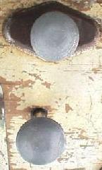
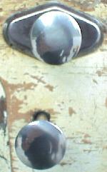
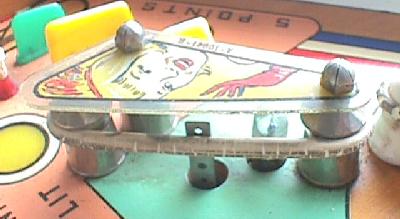
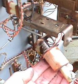
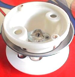
The top of a pop bumper with the cap removed. Note
the two screws that hold the bumper body to the playfield.
Also note the wedge style light socket. This will be
replaced with a bayonet (#47) style socket. The top of
the metal ring of the rod & ring assembly is also visible.
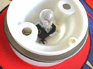
From the top of the playfield,
remove the bumper caps. Usually two small screws holds it in
place (though some are press fit). Then remove the light bulb.
You will see two screws that hold the bumper body to the
playfield, next to the light socket. Remove these two screws.
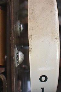
Bottom of the playfield: This picture shows the lamp
socket leads and the rod nuts, and plunger/coil assembly.
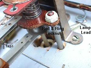
From the bottom of the playfield you need to remove the
two locknuts from the rod & ring assembly.
Then unsolder the two light socket
leads underneath the playfield.
On some games (including this one), there are staples that secure these leads,
which you will have to remove. Now the bumper body and rod
and ring can be removed from the top of the playfield.
Also check the bakelite and metal armature links that slide inside
the coil plunger, which the rod and ring assembly bolt to.
These often crack or break and need replacement. The steel link
breaks the most often. The older Gottlieb version is no longer available, but you
can replace them with new Williams steel armiture links,
part number 01-5492. I do NOT recommend the Williams part
though. They are not hardened steel (like the Gottlieb part), and
often break. You can get a new style Gottlieb metal armature that
is hardened from Pinball Resource.
It is slightly bigger though. So you either have to
grind it smaller, or modify your pop bumper bracket (see pictures below).
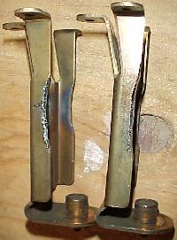
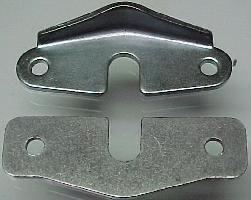
Left: Modified Gottlieb pop bumper brackets
to accomadate the newer (bigger) Gottleib
metal armature plate. Note the sides are
indented with a grinder.
Right: The top of this picture is a new
Gottlieb metal armiture link. These are hardened
steel, and will not break. Below it is the cheap
Williams metal armiture link that is so soft, I can
bend it with my fingers!
Note when re-assemblying the armature plates, the bakelite
spacer mounts closest to the rod & ring nuts, and the steel
link contacts the metal bracket.
Inspect the Rod and Ring.
It is very important you inspect the rod and ring assembly
for defects. If the rods are loose, replace the rod and ring
assembly. If the threaded ends are not square to the rod,
this is also cause for replacing the rod and ring.
Tighten or Re-peen the coil stop.
The coil stop on the pop bumper bracket should be tightened
or re-peened (if it's a riveted coil stop).
Check the pop bumper spring.
The spring that goes over the pop bumper plunger
is probably very tired. You should either replace
this spring, or re-stretch it to the length of
the pop bumper coil.
Install a New pop bumper lamp socket.
Don't even attempt to re-use the old lamp socket. Buy a new
socket from Pinball Resource.
The old socket is probably
corroded anyway, and should be replaced.
After removing the two screws inside the bumper body (and
disconnecting the rod and ring and bumper lamp socket from under the playfield),
lift the bumper body off the playfield. Note
all the dirt and crude that lives under the bumper body!
If you have clear plastic trim platter protectors, there will be lots
more crud under those. Now is a good time to clean the playfield under
the bumpers with Novus2. When finished with the Novus2, wax this
area.
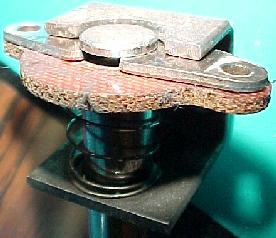
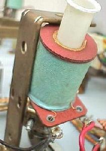
Left: Removing the pop bumper coil and replacing the
coil sleeve.
Right: Note the metal armature link touches the metal
bracket. Also note the two links' openings face
each other, mounting from opposite sides.
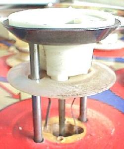
Lifting the pop bumper off the playfield.
Note the chipped bumper skirt.
Trim Platters.
Gottlieb games after 1965 have round mylar (clear plastic film) "trim
platters" that protect the pop bumper area.
Remove the mylar and clean the glue off the playfield with Goo Gone.
Clean the playfield with Novus#2. At this point you can replace or add
the clear trim platters, but I wouldn't unless there's excessive wear.
Note trim platters come two ways: adhesive backed, and non-adhesive.
I personally like the adhesive backed units. They don't shift or move, and
dirt doesn't get under them. Also, the non-adhesive trim platters can actually contribute
to pop bumper wear. As the ball skates across the platter, they shift slightly
on the playfield. The shifting of the platter can cause wear, hence defeating
their purpose.
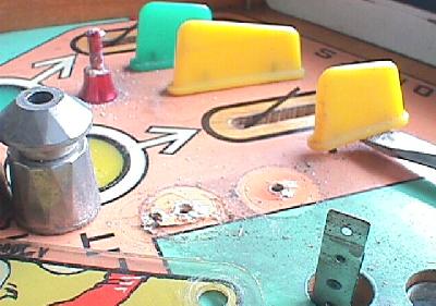
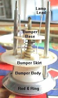
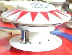
The parts of a pop bumper. The picture on the left was take before cleaning.
The picture on the right was take after cleaning the body, replacing the skirt,
and polishing the ring. Use these pictures for reference when re-assembling.
Note the orientation of the bumper base in these photos; the two lamp lead holes
have extents. These extents do not line up on top of the bumper body's extents.
Clean the bumper body with Novus#2. Replace if cracked
or damaged (bumper bodies aren't expensive). Sometimes the
bumper base will break off inside the bumper body when you
are separating the parts. Replace as needed.
Replace the bumper skirt. They are only 70 cents brand new,
and look lots better, even if the old ones aren't damaged.
Also install a new light socket for the
pop bumper. If you game had 555 wedge type bulbs (as this game does), get #47 bayonet
style sockets. The bayonet #47 light sockets sit lower in the bumper
body. This prevents the bulbs from burning the back side of the
bumper caps.
Fixing Pop Bumper Playfield Wear.
If you have excessive playfield wear around the pop bumpers,
there is an easy fix. Match the playfield paint and apply it
to the bottom side of a new (non-adhesive backed) trim platter. Then when the trim platter
is installed, it covers the playfield wear with the same color as
the playfield, shown through the clear mylar. A very clean
fix without altering the playfield itself.
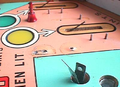
Left: Ready to add a new light bulb.
Right: The finished product.
Re-assemble from the top of the playfield. If your replacement
bumper skirt has a small "tit", it goes
towards the top of the playfield (it stops the ball from balancing
on the top edge of the skirt). Secure the
bumper body to the playfield with its two screws. Then
from underneath the playfield, put the locknuts back on the rod & ring
assembly. Do NOT over-tighten the rod and ring locknuts, or you
will break the rod! Re-solder the light
socket.
Clean the Spoon Switch.
If you did install new bumper skirts, the bumper switch that the
new bumper skirt activates will need re-adjusted. This switch is
called the "spoon" switch (because the bumper skirt's "penis"
rides inside its spoon-like receptical).
But before you do that, remove that entire spoon switch assembly from the game.
Note the crud that lives inside the "spoon". This accumulates from
(wrongly) lubricating the spoon. Clean the crud out with alcohol and
leave this DRY (though some people say to lub the spoon with
white grease, I disagree, as it will only attract dirt).
Polish the surface with 1000 grit sandpaper (or higher grit).
Re-install and adjust the bumper skirt activated spoon switch.
Note if there is too much tension on the skirt's "penis" from the
spoon switch, this will cause the "penis" not to center. There should
be just a bit of tension, and no more. Also make sure the penis
doesn't ride outside of the spoon switch too much (or the skirt switch
will stick on, and lock the pop bumper coil on). You will have to
move the position of the spoon switch to adjust this.
For a final touch, install new pop bumper caps (if available
for your game). At $5 each, they really make your game look
sharp. Save your original pop bumper caps.
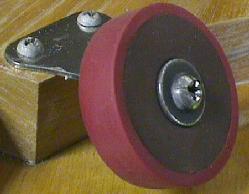
3c. The Mechanics: Performance Tips
Installing a new coil sleeve on the
slingshot kicker.
Replacing Coil Sleeves.
If you haven't replaced any coil sleeves, now is the time
to do that. You only need to do this on things
that will make a difference in game play. This includes the
slingshot kickers and the pop bumpers (if you didn't replace the
sleeves when you rebuild them). Replacing the coil sleeve on other coils
that don't impact game play is a waste of time and money.
On the slingshot kicker or pop bumpers underneath the playfield,
you'll need to remove the two screws that hold the coil bracket in place.
This will allow you to remove the coil and replace the coil sleeve.
If your game uses metal coil sleeves, these definately need to be replaced
with new nylon coil sleeves!
Polish the Pop Bumper Rod and Ring.
As discussed in the above rebuilding the pop bumpers section,
the pop bumper ring needs to be polished. Even new rod and ring assemblies need
polished! When rebuilding the pop bumpers,
buff the part of the pop bumper metal ring that contacts the ball.
It should be as smooth and
shiny as a mirror to reduce friction. This allows more of the pop bumper's
energy to be transfered to the ball.
A new rebound rubber with an added mini-flipper rubber.
Increase Playfield Slope.
As simple as this seems, if you increase the angle of your pinball
machine, it will play faster! Try moving your two inch rear leg levelers
up all the way. Then put your front leg levelers down all the
way (or remove them!). If you playfield is clean and waxed, this
will increase ball speed dramatically.
Make sure your Flipper Return Spring is not Over-wound.
This happens a lot. Unfortunately, sometimes it is done on purpose to try
to "fix" a flipper that stays up when the button is released.
(On an otherwise clean, adjusted flipper, this kind of sticking occurs
because of a magnetized coil stop. The only real cure for
this is to replace the coil stop.) With a
properly adjusted flipper return spring, there will be only the weakest of
return pressure on the flipper linkage. You will know you have it right if
the flippers just BARELY swing to their at-rest position when you
raise the playfield up. The weight of the flipper bats causes them to be sluggish,
which should give you an idea of how weak the return springs really are
when properly adjusted.
Clean and Adjusted EOS Flipper Switches.
If the EOS switch or cabinet switch contacts are
dirty or pitted, they will have some resistance that will make
the flippers weakers. Clean the EOS switch contacts and adjust them.
EOS switches should be solidly closed and open about 1/8", only at the very end
of flipper travel. When you check EOS adjustment, operate the flipper
by pushing the plunger into the coil until it hits the stop. Don't
just rotate the flipper bat or push on the linkage because slop in
the linkage will keep you from getting an accurate adjustment.
After adjustment, be sure that the EOS switches really do open when
the flipper is energized. If they stay closed, the flipper coil
will burn out.
If the flipper still seems really weak, look for cold or broken solder joints
on the wires at the EOS switch and where they attach to the coil.
While you're at it, clean the flipper button contacts too. Note you
should use a metal file for cleaning these switch contacts, since
they are tungsten and won't file well with a flexstone.
Also check the wires going from the flipper coil to the EOS switches.
They should be stranded wire, not a solid core wire. If it is
solid core (very common on Williams games), replace it with a
good quality stranded wire. Solid core wires can easily break
internally, making the flippers weak.
Rebuild the Flippers and Hi-Power Flipper Coils.
Previously discussed in rebuilding the flippers.
Having good, strong flippers is
very important; flippers are the game's direct connection to the player!
Weak flippers will ruin any game. Rebuilding the flippers includes
replacing the coil sleeve and the plunger link, and checking the
old plunger for mushrooming. Hi-power Gottlieb EM flipper coils are also available from
Pinball Resource.
These are about 20% more powerful.
More Powerful Pop Bumpers and Slingshots.
You can increase the power of your pop bumpers and slingshots
easily by decreasing their coil resistance. The lower the
resistance, the more powerful the coil. Increased power means
the ball kicks around more and makes the game more lively. To do this, you'll
need to remove about 10% to 20% of the coil windings from
the coil (don't get greedy and try to remove more than
20%; if you get below 2 ohms the coil will become a "short" and no long work!).
This is very easy, and only takes a few minutes.
I do this when I'm replacing the coil sleeve on a pop bumper.
Just unwind three "layers" of wire from the coil.
This will lower the coil resistance, and make the device stronger.
Note you do not have to unsolder the coil from the game to do this!
Here are the steps:
- Un-wrap the paper wrapping from the coil and save it.
- Cut the outside coil winding wire from the solder lug (do not
cut the inside coil winding wire! You can't unwrap wire from the inside).
- Un-wrap three layers of wire. A layer is about 40 turns of wire.
- After the third layer is unwound, leave about two inches of wire
and cut off the extra wire.
- Sand the extra two inch length of wire to remove the painted enamel insulation.
- Put the two inch wire length through the solder lug hole from which you originally cut
the coil winding. Wrap the remainding wire around the solder lug.
- Put the coil wrapper back on the coil, and secure it with a 1/2 inch
piece of electrical tape.
- Replace the coil (if removed).
- Solder the wire lug to secure the re-attached coil winding.
I don't tend to do this modification to the slingshots on games
with small flippers. The problem
with really strong slingshots is the game gets a lot harder to play!
The ball kicks around more, and is much hard to catch in the flippers.
Not a problem for long flipper games, but short flipper games
become quite difficult to control the ball.
But I definately do this modification to pop bumpers. Good strong
pop bumpers makes a game much more lively and fun. Be your own judge.
Start with doing the pop bumpers and see how you like it.
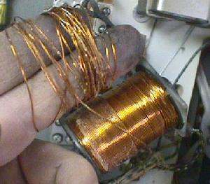
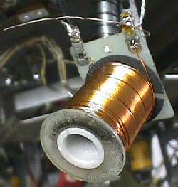
Left: Un-wraping the coil winding from the coil. Here we're about
half way through the first coil layer.
Right: Three layers of coil windings have now been removed. An extra
two inches of wire is left, and sanded clean. Then it's inserted through
the (previously cut) solder lug. The remainder will be wrapped around the
solder lug, and re-soldered.
Re-face the Rebound Rubber.
Ever notice when you plunge the ball how "dead" the upper ball arch's
round rebound rubber seems? Even a brand new rebound rubber is hard and
dead. But you can re-face these rebound rubbers to give them added bounce
and life. This makes the game seem much "snappier" and fun.
Just stretch a red mini-flipper rubber over the rebound rubber
(don't use black mini-flipper rubbers, they are too hard). This will
give instant life to an old, dead rebound rubber, or to a new rebound
rubber. It is also easier to clean
and replace. Mini-flipper rubbers are used on newer games like Twilight
Zone and the Addams Family.
3d. The Mechanics: New Under-Playfield & Backbox Lamps
When replacing bulbs, it's also a good idea to clean and re-tension
the light socket. The Pinball Resource
has a rubber pencil-like
socket cleaner that works well. I also use a set of needle nose
pliers and gently squeeze and tighten the sides of the lamp socket after
removing the bulb. This should give the socket better contact to
the lamp.
Unfortunately, if a lamp socket is intermittened, or causes the
bulb to light dim, there are other problems. Lamp sockets are
pressed together with an insulating fiber ring. With time, this
ring shrinks, and causes the metal parts to fit loosely together.
This allows air (and humidity) to get between the parts, and
cause corrosion. This makes the socket either not light, or
light dim.
In this case, retensioning the socket and cleaning won't work.
You have to replace the socket!
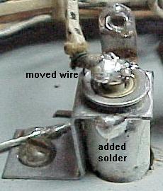
Left: Fixing sockets that refuse to work. If you can't
replace a socket, you can usually fix it (except on Bally games!). First move the
tabbed wire to the tip of the socket base. Then add
some solder to the round tube and the base of
the socket. You will need to sand these surfaces before
you try and solder to them, otherwise the solder won't stick.
Right: Over zealous factory soldering. Sometimes the factory
solders the general illumination wire for the socket
so the attachment screws can't be removed. This isn't
so bad on Gottlieb games, which use slot head screws.
But on Williams games that use phillips head screws,
if solder gets inside the phillips "x", there is no easy
way to remove the attachment screw. This makes replacement
very difficult.
In some cases, you can not replace the socket. Some types of
sockets are no longer available. Or the existing socket just
can't be removed. Often the attachment screw is soldered over,
so you can't put a screw driver in the screw's slot. This makes
replacement difficult!
You can fix a socket though (except on Bally games - replace them!) To
do this you'll have to sand the socket area clean with sandpaper,
or the solder won't stick. You can move the wire that connects
to the socket's tip right to the tip itself. Then solder between
the socket's mounting base and it's circular bulb recepticle.
Make sure you replace all bulbs with #47 (instead of #44) bulbs.
This is especially important for the bulbs in the backbox, no exceptions!
The additional heat given off by the
original #44 lamps can help delaminate the paint from the backglass.
3e. The Mechanics: Sunken/Cupped/Low/Loose Playfield lamp Inserts
This is a very common problem, especially on older woodrail pinballs.
The plastic lamp inserts in the playfield (PF) shrink in size, and
become lower than the playfield playing surface. Or the inserts just fall
out when the playfield is raised! If an insert is too low, this will
make game play odd. Sometimes to the point where the ball will
get hung up on the low insert.
On 1950s pinballs in particular, it is NECESSARY to remove ALL
the playfield inserts and to reseat them. I can guarentee they
are all sunken below the level of the playfield. If left alone,
this will wear the playfield around the inserts, and make the
game play badly. On 1960s and 1970s pin games this is less
of an issue, but as time marches on, these games too will need
their inserts re-seated. (I have needed to do this on games as late
as the 1980s.) If you are going to touch up and clearcoat a playfield,
reseat the inserts BEFORE you do any of that work.
First try and get the insert out of the playfield.
Sometimes they just fall out, other times they are
a bear to remove.
Use a socket
to gently knock the insert out from the
bottom of the PF using a small rubber mallet.
The reason sockets work very well is because they come
in so many sizes, and you probably have a toolbox full of them.
Use the largest that will fit in the insert
route from under the playfield.
Do NOT force the inserts out! If they don't come out
with just a few light taps of the mallet,
use a hair dry from under the playfield
to soften the glue, allowing the insert to come
out easier. Do not use a heat gun (too hot).
If you pound the insert real hard it can break the
top off the insert, leaving the sides still glued
in the playfield. This is fixable, but it's obviously
ideal to get the insert out in one piece. The hair
dryer tip works really well for this. Put the hair
dryer nozzle right up against the insert from the BOTTOM of the playfield,
and turn the hair dryer on "high". Feel the insert from the top of the playfield.
Once warm, remove the heat and tap with the insert with the socket/mallet from
the bottom of the playfield to pop out the insert.
Sometimes inserts are "cupped". If this is the
case, the top of the insert will need to be
leveled before re-installing. If the insert has no
text or graphics, remove the insert and block sand
the top face flat (turn the insert face down
on a piece of 400 grit wet/dry sand paper on a solid block and sand).
If there are graphics or text on
the insert, water-thin Super Glue can be added to the top in THIN layers
to build it. After several layers
(and the superglue is dry), turn the insert face down
on a piece of 320 or 400 grit wet/dry sand paper on a solid block and
sand (wet). Then move to 600 grit and finally 1200 grit,
then reinstall. When you polish the playfield (Novus2) that will
also polish the leveled insert.
Note using heat to soften the insert and then trying to push
the top of the insert up/flat really does not work. The added
heat will only make the insert worse, and it usually is not
correctible.
Now its time to reinstall the insert.
There are two ways to go.
Thick superglue (SG) around the edge of the
insert, reseat, level, wipe off any
excess from PF, let dry. Then (optionally)
add water thin Superglue around the top-side edges of
the playfield/insert to seal
the insert better and permanently. Any SG that gets
on the playfield should be wiped off immediately before
it solidifies. Polish with Novus2 when dry.
If the playfield was waxed before this process that
is a good thing to some degree - the wax will prevent
any excess waterthin Superglue from taking hold on
the top side of the playfield as you wipe it off
(but don't over-wax as wax tends to get into the gaps
between the playfield and inserts, causing glue adhesion
problems between the insert and playfield).
If using the Super Glue method to glue inserts,
make sure the playfield is CLEAN *before* attempting
the re-glue. Otherwise when you wipe off any excess super
glue from the top of the playfield, you can accidentally "lock in"
the dirt to the playfield's finish. Short of sanding, you
will never get that dirt out.
The other way is to take some brown
paper packing tape (like used at butcher
shops, not the plastic shipping tape),
and put a layer or two around the edge
of the insert. Wrap the brown tape so it is
slightly below the top side of the insert
(so the tape won't show when the insert is installed).
Trim the excess tape on the bottom side of the
insert with a razor blade.
Wrap enough tape around the insert so it fits snug into the
playfield. Then remove the insert and put yellow
carpenter's glue around the PF hole, install
the insert and level it.
Work some carpenter's glue into the insert/playfield edges
from the top side of the PF, and
check the levelness again. Wipe up extra glue
with a wet rag, let it dry overnight.
The second method is less caustic and
reversible. It's also easier for the newbie,
but both methods work well.
In regards to leveling the insert. I like to
use a piece of plastic acrylic that is larger
than the insert. Lay this on the top side of the PF.
Push the insert up from the bottom side of the PF
while keeping pressure on the acrylic plastic on
the top side. This should make the insert level.