2a. Before Turning the Game On: Game Assembly & the Black/White Connectors.
After setting up a System3 to System7 game, before powering on, double check
the cabinet/playfield to backbox connectors! (Connectors at the head/body split.)
Williams makes it so connectors can not be put together incorrectly, as they're all
different shapes and sizes, right? Well, not quite!
The COLORS of the connectors and the wire colors need to be noted too.
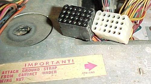
Specifically, there is a pair of white connectors and a pair of black connectors that are
physically identical. IMPORTANT: Make sure to get these connectors plugged-in correctly!
If these connectors are cross-connected, the solenoid voltage (28 volts) will
be applied to the +5 volt logic. This will instantly fry numerous chips
on the CPU and driver boards, and even the sound board.
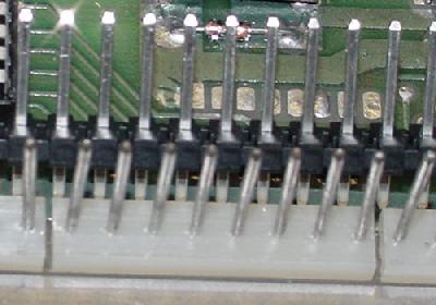
The plug compatible black and white connectors (Firepower). Plug these together
incorrectly, and the CPU/driver/sounds boards will be wasted in a flash!
|
BUT WAIT! It's VITAL to check the wire colors too. At the plug connectors,
the mating wires on the female and male plugs should be the same wire color.
That is, a Green/White wire on one plug should mate to a Green/White wire on the
corresponding plug. Though
certainly not common, Williams has mistakenly mixed the plug colors.
Remember, the wire colors matching is more important than
the plug colors matching! It can be assumed that 99% of the time Williams
used the correct plug colors (black-to-black and white-to-white),
so matching plug colors is a good approach. But now you don't
want to be that 1% where Williams mis-matched the plug colors right?
VERIFY THE WIRE COLORS ON THE TWO MATING PLUGS.
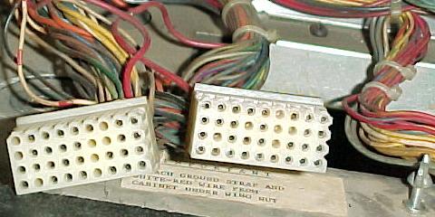
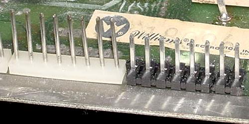
See the picture below where Williams used two *white*
connectors of the exact same type matching to two black connectors.
The only way to match these connectors is
by wire color! So the safe and sane person will always verify the wire colors
match on both the male and female connectors, before turning the game on!
Oops! Williams assembled this Black Knight with two identical *white*
connectors (instead of one white and one black). The only way to match
these plugs is by wire color. Again, plug these together incorrectly, and
the CPU/driver/sounds boards will be wasted in a flash!
 |
Oops! I Mis-Connected the Plugs and Turned the Game On!
If the plugs were cross-connected, and the game turned on,
there are some likely things that could happen (this example is
Black Knight; what blows exactly can be game specific, and
may also depend on how long the game was powered on). First the
obviously broken stuff was:
- General Illumination lights.
- Score displays unlit.
- Flippers permanently energized and stuck on.
- Drop target reset coil energized and stuck on.
- Sound board wouldn't even do self test.
- Blows fuses.
In this Black Knight example, here's what fried, and what survived:
- Power supply board was OK.
- Sound board Amp IC blown (flipper was being energized
through this IC).
- CPU board needed IC7 (7404) and IC5 (7402) replaced, as these
were shorting +5V and ground through them (these are connected
to the memory protect circuit and diagnostic switches). It also needed IC12
(7408) replaced to get the CMOS RAM working again (until this
was replaced, the game always came up in test mode).
- Driver board needed IC17 (7406) replaced to fix a bunch of
switches that wouldn't read. Also needed IC11 (6821 PIA)
replaced to fix some row inputs that were stuck "on"
(surprisingly, the 4049's CMOS chips survived)
So the moral of the story is, "don't cross-connect the connectors"!
Loose/Broken Wires in the Connectors.
When assembling the game,
carefully check all of the connectors between
the head and the cab. Sometimes a connector pin will
slip out of the plastic connector housing, or a wire will break
very close to where it is crimped to the connector pin.
This can cause a great deal of frustration when a "it was working
before" game now does not work, after it is moved.
Don't Forget the Grounding Strap.
In the backbox behind the backglass, there is a ground wire/strap which
attaches to a wing nut. This ground strap is very important, and
must be connected. On many system3 to system7 games, some features
of the game won't work (or won't work properly) if it's not attached to the
wing nut and the wing nut tightened.
Also later games from Firepower on had an
addition white-with-red trace grounding wire coming from the
playfield that needs to be cinched under the wing nut in addition
to the braided ground wire.
2b. Before Turning the Game On: Check the Coil Resistance.
A very good idea for any unknown game just purchased is to check all
the coils' resistance. If the game is new to you, and you have not
powered it on, a quick check of coil resistance will tell you a lot
about your new game. This takes about one minute and can save you
hours of repair and diagnosing work.
Any coil that has locked on (usually due to a short solenoid driver board
transistor) will heat up and have a lower
total resistance. This happens because the painted enamel insulation
on the coil's wire burns, causing the windings to short against
each other. This will lower the coil's resistance, causing the coil
to get even hotter. Within a minute or so the coil becomes a dead short,
and usually blows a fuse.
If the solenoid driver board (SDB) transistor is repaired, and the game is powered
on with a dead-shorted coil, this will blow the SDB's same transistor again
when the coil is fired by the game for the first time! There is no sense
making more work for yourself. So take 60 seconds and check all the coils'
resistance BEFORE powering the game on for the first time.
In order to check coil resistance, put your DMM on its lowest resistance
setting. Then put the DMM's red and black leads on each coil's lugs.
A resistance of 2.5 ohms or greater should be seen. Anything less than 2.5
ohms, and the coil and/or driving transistor may be bad.
Now remove the wire from one of the lugs of the coil, and test the coil
again. If the resistance is still the same (low), the coil or diode is bad (and
also perhaps the driving transistor).
If the resistance is higher than 2.5 ohms, the coil is good but
the solenoid driver board transistor is shorted and will need to be replaced.
Lastly, the coil's 1N4004 diode could
be shorted too, giving a false low coil resistance. Cut one diode
leg from a coil lug and retest the coil's ohms.
Remember when reconnecting the wires to the coil that the power wire (usually two
wires or thicker wires) goes to the coil's lug with the BANDED side of
the diode attached. The thinner wire is the coil's return path to ground
via the driver transistor and attaches to the coil lug with the non-banded
side of the diode attached.
If a low resistance coil is found, also suspect the associated driver
board transistor as bad. A low resistance coil is a red flag, a warning,
that there may be problems on the driver board.
2c. Before Turning the Game On: the Power Supply
(Explaination, Testing, Fuses, Bridges, Test Points, Modifications, Repair).
IMPORTANT! Before Turning the Game On!
After all the above items in section two ("Before Turning the Game On") have been
inspected and fixed, now it is finally time to actually power the game on! But before
proceeding, remove the Lamp matrix and Solenoid fuses from the game (fuses F2 and F3
on the power supply board).
This is VERY important! If there are problems on the CPU or driver board, having these fuses
removed will prevent any further damage to the game.
For example, when the CPU board does not work, and the game is powered on,
often all the coils will energize and all the lamps will lock on. This
can burn the coils and lamps at minimum. The same thing can happen if the
game is turned on with the CPU board missing, or if the "blanking" signal
(pin 37 of the interconnector) stays low.
What if the game Locks-Up or "Resets"?
Please see the section that directly addresses this
here. A complete systematic
approach is shown to fix those problems. But if the modifications
are performed as described in this section, this should reduce
any reset or lock-up problems.
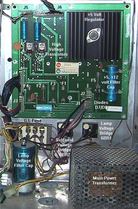
What Voltages does the Power Supply Output?
The "power supply" (that is, the transformer, the power supply board,
and the backbox attached bridge rectifiers/filter capacitor) outputs
the following voltages:
- +5vdc regulated logic power.
- +12vdc unregulated,
often called "unregulated 5 volts" by Williams, because on the CPU board the
unregulated 12 volts gets knocked down to about 5 volts.
- +18vdc lamp matrix power (for game controlled lamps).
- +28vdc solenoid/flipper power.
- +/- 100vdc score display power.
- 6.3vac General Illumination lamp power.
- +50 volts DC (for flippers), Firepower2 and later, via an additional
flipper power supply board.
The power supply board takes in 18.6 volts AC (9.3 volts AC times two)
from the transformer, and outputs
+12 volts DC, and +5 volts DC. In addition it
takes in 90 volts AC from the transformer and outputs +/- 100 volts DC.
The unregulated 28 volts DC for the solenoids and the 18 volts DC for
the lamp matrix power actually does not use the power supply
board (this is handled by the backbox mounted bridge rectifiers and
filter capacitor). But these two voltages do go through
the power supply board for fusing, but neither is manipulated or altered.
On System7 power supplies, 6.3 volts AC also
comes into the power supply board, but only to provide a fuse and a G.I relay
to the circuit (there are three additional connectors on a system7 power supply
for GI input and output, and for control of the GI relay).
Also note that the Sound Board has its own dedicated power supply.
So if the sound is not working, don't mess with the game's main power supply.
Early power supplies (first two system3 games, Hot Tip and Lucky Seven)
also routed the G.I. through the power supply board, and
contained a 300 volt feed for the display
driver that was later dropped. All power supplies boards from System3
to System7 are interchangeable (except for maybe the first two system3
game power supplies which used the 300 volt feed and GI power supply connector).
Transformers on earlier games also used slightly different plug
arrangements. Hot Tip/Lucky Seven and System7 games routed the GI power through the
power supply board. System3 (World Cup and later)
to System6 games had direct connections to the
fuse card for the GI circuit. If swapping transformers, make sure the
GI power is routed properly through the fuse card or power supply,
as dictated by the game in question. Also the last three System7 games (Firepower2, LaserCue,
Starlight) used 50 volt flipper coils (compared to the rest of the 28 volt game coils),
so these trasformers are different too.
The "power supply" on a System6 game.
Picture by Mark.
|
|
Fuses.
System3 and 4 games (all games through Flash) do not have the fuse for the Flipper
power on the power supply. Instead the fuse is located under the playfield near the
flippers. Fuse holder F4 is present on the power supply on these games, but the
circuit isn't used on games from World Cup through Flash, so fuse F4 can be removed.
Likewise on the last three System7 games (Firepower2, LaserCue, Starlight); these
games used 50 volt flipper coils, and had a separate 50 volt power supply board
for the flippers. The F4 power supply fuse is therefore not used (instead the
50 volt flipper power supply board has a F2 fuse 5amp slow blow).
The first two System3 games from Williams (Hot Tip and Lucky Seven) use F4 as the GI
fuse. These games routed the GI power through Power Supply board
and the .156" connectors. The photo below shows the GI connector from a Hot Tip and
the associated burn marks on the connector. Williams smartly removed the GI from the
Power Supply board by World Cup, but had a lapse of judgment and put it back onto the
Power Supply board in System7 games (because the power supply board also got
a G.I. relay), albeit with a larger Molex connector, but the
same burnt connector results.
Hot Tip/Lucky Seven showing the lower left
burnt G.I. connector on the power supply board.
Picture by Mark.
|
|
Main fuse:
All system3 to system7 games use a main fuse of 7.5 amp fast blow in
the front of the cabinet (accessed through the coin door).
System 3 Fuses.
Power Supply Fuses:
- F1 = Score display 90 volts AC, .25 amp Slow Blow.
- F2 = Solenoids 28 volts DC, 2.5 amp Slow Blow.
- F3 = Lamp matrix 18 volts DC, 8 amp Fast Blow.
- F4 = GI fuse 6.3 volts, 20 amp Fast Blow, Hot Tip and Lucky Seven only.
World Cup to Flash, this fuse is not used.
- F5 = +5 volts DC logic, 4 amp Fast Blow.
Sound Board Fuses (except Hot Tip & Lucky Seven):
- F1 = 9.3 volts AC, 4 amp Slow Blow (mis-labeled 2 amp on some schematics).
Backbox Panel Fuses (located below power supply board):
- Fuse Card = 28 volt flippers, 20 amp Fast Blow (not present on
Hot Tip and Lucky Seven).
Playfield Fuse (located under playfield):
- 28 volt flippers, 10 amp Fast blow, on games before Flash.
Power Supply Bridges (located on power supply board):
Backbox Bridges (located below power supply board, 35 amp, 400 volts):
- 6BR1 Blue Wires = Lamp matrix 13.5 volts AC inputs.
- 6BR2 Green (or Red) Wires = Solenoids 25.5 volts AC inputs.
System 4 Fuses.
Power Supply Fuses:
- F1 = Score display 90 volts AC, .25 amp Slow Blow.
- F2 = Solenoids 28 volts DC, 2.5 amp Slow Blow.
- F3 = Lamp matrix 18 volts DC, 8 amp Fast Blow.
- F4 = Not used on games before Flash. Starting with Flash,
F4 is the flipper fuse (10 amp Fast blow).
- F5 = +5 volts DC logic, 4 amp Fast Blow.
Sound Board Fuses:
- F1 = 9.3 volts AC, 4 amp Slow Blow.
- F2 = 9.3 volts AC, 4 amp Slow Blow.
Backbox Panel Fuses (located below power supply board):
- Fuse Card = 6.3 volt General Illumination, 20 amp Fast Blow.
Playfield Fuse (located under playfield):
- 28 volt flippers, 10 amp Fast Blow (games before Flash only).
Power Supply Bridges (located on power supply board):
Backbox Bridges (located below power supply board, 35 amp, 00 volts):
- 6BR1 Blue Wires = Lamp matrix 13.5 volts AC inputs.
- 6BR2 Green (or Red) Wires = Solenoids 25.5 volts AC inputs.
System 6 Fuses.
Power Supply Fuses:
- F1 = Score display 90 volts AC, .25 amp Slow Blow.
- F2 = Solenoids 28 volts DC, 2.5 amp Slow Blow.
- F3 = Lamp matrix 18 volts DC, 8 amp Fast Blow.
- F4 = Flippers 28 volts DC, 10 amp Slow Blow (GI fuse on shuffle alleys).
- F5 = +5 volts DC logic, 4 amp Fast Blow.
Sound Board Fuses:
- F1 = 9.3 volts AC, 4 amp Slow Blow.
- F2 = 9.3 volts AC, 4 amp Slow Blow.
Backbox Panel Fuses (located below power supply board on a fuse card):
- 6F1 Yellow Wires = General Illumination 6.3 volts AC, 20 amp Fast Blow.
- 6F2 Gray Wires = Logic 9.3 volts AC supply, 4 amp Slow Blow.
- 6F3 Gray Wires = Logic 9.3 volts AC supply, 4 amp Slow Blow.
No playfield fuses, as the fuse F4 on the power supply board is now used
for the flippers.
Power Supply Bridges (located on power supply board):
Backbox Bridges (located below power supply board, 35 amp, 400 volts):
- 6BR1 Blue Wires = Lamp matrix 13.5 volts AC inputs.
- 6BR2 Red Wires = Solenoids 25.5 volts AC inputs.
System 7 Fuses.
Power Supply Fuses:
- F1 = Score display 90 volts AC, .25 amp Slow Blow.
- F2 = Solenoids 28 volts DC, 2.5 amp Slow Blow.
- F3 = Lamp matrix 18 volts DC, 8 amp Fast Blow.
- F4 = Flippers 28 volts DC, 10 amp (2 flippers) or 15 amp (3 or 4 flippers)
Fast Blow (on shuffle alleys this is the GI fuse). This fuse is NOT used
on Firepower2, LaserCue, Starlight.
- F5 = 9.3 volts AC (input for +5 volts), 7 amp Slow Blow.
- F6 = 9.3 volts AC (input for +5 volts), 7 amp Slow Blow.
- F7 = General Illumination for pinballs, 6.3 volts AC, 20 amp Fast Blow.
Flipper Power Supply (Firepower2, LaserCue, Starlight ONLY):
- F2 = 48 volts AC, 5 amp Slow Blow.
Sound Board Fuses:
- F1 = 9.3 volts AC, 4 amp Slow Blow.
- F2 = 9.3 volts AC, 4 amp Slow Blow.
Backbox Panel Fuses:
No playfield fuses, as the flipper fuse F4 is now on the power supply board
or the flipper power supply board.
Power Supply Bridges (located on power supply board, 35 amp, 400 volts):
- BR1 = 9.3 volts AC inputs that ends up being +12 volts and +5 volts logic.
Backbox Bridges (located below power supply board, 35 amp, 400 volts):
- 6BR1 Blue Wires = Lamp matrix 13.5 volts AC inputs.
- 6BR2 Red Wires = Solenoids 25.5 volts AC inputs.
Diagnosing a Blown Solenoid Fuse.
If any of the game's solenoid fuse(s) blow immediately
at power-on, here's some things to check:
- First check the pop bumpers and slingshots to see if
their "activation" switches are stuck closed (the switches that the ball triggers
to make the bumper work). These "special solenoids" are unlike other
coils in the game in that if their activation switch is stuck closed, it will keep the
coil turned on, and the fuse will blow.
- With the game off, use a DMM and check the ohm reading of each
and every coil in the game.
On two lug coils just put the meter leads on the coil's lugs
(on three lug coils there is a "common" lug, measure the resistance
between the common lug and the other two lugs).
All coils should be 2.5 ohms or greater. If a coil
is less than 2.5 ohms, the coil is bad and essentially a dead short,
hence causing the solenoid fuse to blow.
- If the flipper solenoid fuse is blown, this is most often a
bad or mis-adjusted EOS (End of Stroke) switch. See the flipper
section for help with that.
- If a coil is less than 2.5 ohms, there is probably a reason
this happened - the coil locked on, heated up, and melted the
insulation off the coil's windings. This causes a short between
the windings, and lowers the coil's overall resistance.
Usually this most often due to a shorted driver transistor which keeps
the coil energized while the game is powered on.
- For all coils found with less than 2.5 ohms of resistance,
disconnect the wire(s) from one of the coil's lugs. For a two
lug coil, there is a power wire which is usually a thicker wire
or often two thicker wires. This brings power to the coil and is connected
to the coil lug with the banded side of the diode attached. The other
coil lug has the return wire which goes to the CPU board.
I remove the thinner return wire because it is easier, but
removing either will disconnect the coil from the circuit.
- Power the game on with a new solenoid fuse. Does the fuse
still blow? If not, you have found the start of your problem
(the bad coil - now you need to find out what made the coil bad!)
If the fuse still blows, look for another bad
coil or perhaps a short from the coil voltage to ground.
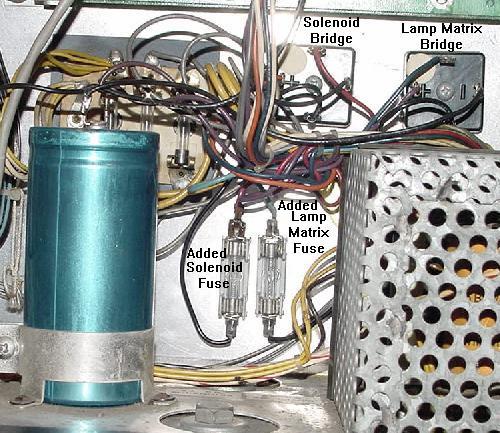
Adding Two Fuses to a System3 to System7 Games.
All Williams games prior to 1987 do *not* have fuses on the
input side of the backbox mounted bridge rectifiers. This is
a bad design, and one that Williams later fixed.
The two bridge rectifiers mounted to the backbox are the
lamp matrix and solenoid bridge rectifiers. If either of
these bridges shorts, or the large backbox mounted 30,000 mfd
lamp matrix capacitor shorts, the main power fuse *should* blow.
But if this single fuse was "over fused", a fire could result!
Added fuses in a Firepower to the input (AC) side of the solenoid and
lamp matrix backbox bridges.
|
|
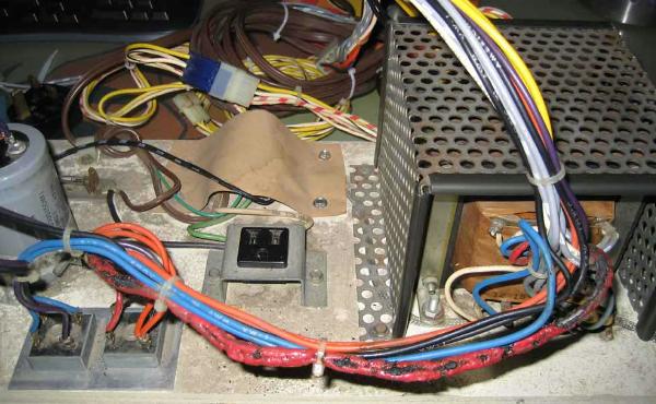
Williams Varkon pinball. Here the solenoid or lamp matrix bridge shorted
on the input side. Without the input fuse (as the game was shipped from the
factory), the red 18 gauge wires got so hot they melted! Luckily the game's
main fuse finally blew, saving this game from a certain internal fire.
|
|
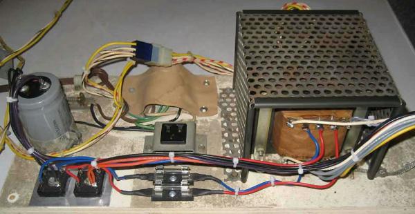
Here's the Varkon after the owner repaired the melted wires and added the
two suggested fuses to the input (AC) side of the solenoid and lamp matrix bridges.
|
|
To fix this problem is simple. It requires two fuse holders (available
at Radio Shack),
two 8 amp slow blow fuses, and two pieces of 18 gauge wire. Here are
the instructions:
- In the backbox, beneath the power supply board,
locate the bridge with the BLUE wires (6BR1,
for the lamp matrix).
- Using a 1/4" hex head sheet metal screw, mount a fuse
holder right next to this bridge rectifier.
- Disconnect one of the blue wires from
this bridge (either blue wire, it does not matter).
Often these wires are soldered to the bridge.
The blue wires are the AC input wires to the bridge.
- Solder this removed blue wire to one end of the newly installed
fuse holder.
- Solder a new wire from the other end of the newly
installed fuse holder, to the lug of the bridge rectifier
where the blue wire was originally disconnected.
- In the backbox, beneath the power supply board,
locate the bridge with the RED wires (6BR2,
for the solenoids).
- Using a 1/4" hex head sheet metal screw, mount a fuse
holder right next to this bridge rectifier.
- Disconnect one of the red wires from
this bridge (either red wire, it does not matter).
Usually these wires have lug connectors (but they
could be soldered).
The red wires are the AC input wires to the bridge.
- Solder this removed red wire to one end of the newly installed
fuse holder.
- Solder a new wire from the other end of the newly
installed fuse holder, to the lug of the bridge rectifier
where the red wire was originally disconnected.
- Install 8 amp slow blow fuses in both fuse holders.
Testing a Bridge Rectifier.
The following test will check if a bridge has an open
circuit or a short.
- Turn the game off.
- Put the DMM on diode setting.
- Put the black lead of the DMM on the "+" (positive) terminal of the bridge.
- Put the red lead of the DMM on either AC bridge terminal.
Between .4 and .6 volts should be seen. Switch the red DMM lead to the other AC
bridge terminal, and again .4 to .6 volts should be seen.
- Put the red lead of the DMM on the "-" (negative terminal of the bridge.
- Put the black lead of the DMM on either AC bridge terminal.
Between .4 and .6 volts should be seen. Switch the black DMM lead to the other AC
bridge terminal, and again .4 to .6 volts should be seen.
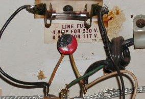
The Varistor and AC Line Filter.
Near the front left of the main cabinet, next to the auxiliary power plug,
are the AC line and the Varistor.
The Varistor is a voltage spike protection device, and looks like a large red ceramic
disk capacitor. This is wired across the terminals of a small metal box (the
line filter). The varistor is a one-time
surge suppressor. When a power surge or voltage spike is sensed, the varistor's
resistance rapidly decreases, creating an instant short path for the over-voltage.
Since electricity takes the shortest path of least resistance, the voltage
spike goes through the Varistor, instead of through the entire game's circuit boards.
Because the varistor creates a short circuit, the varistor and the line fuse
are be damaged in the process.
The game will run fine without the varistor, but is no longer
protected from voltage surges and spikes.
A fried varistor.
(photo by Jean - JMBD).
|
|
The Line Filter (small metal box), is used to suppress radio frequencies.
House wiring acts like a big antenna picking up television, cell phone, radar,
and other signals. These frequencies can interfer with the CPU board.
The same thing applies in reverse, and the filter
prevents the high frequencies from the game flowing back into the AC
circuit.
Cracked Header Pins.
A very common problem on all power supplies from this era is
cracked header pins. Microscopic cracks can develop in the header
pins soldered to the power supply board from
vibration and inserting/removing connectors.
The best way to fix this is to resolder the header pins. NOTE:
it is *highly* recommended that the old solder be removed, before
adding new solder! This can be done using a solder removal tool,
as documented in the document at
pinrepair.com/begin.
Also look for any damaged or burnt header pins. Replace them now
if any are found!
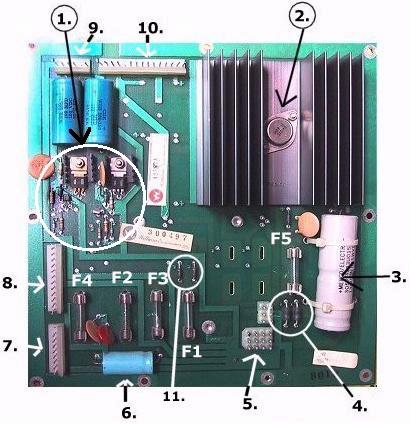
Suggested Power Supply Upgrades.
Please refer to this KEY picture to find the components
involved in the upgrades mentioned below (this is a system6
power supply board, but this is essentially the same power
supply as used on system3 to system7, though system7
power supplies are slightly different).
Picture by Mark.
|
|
Upgrade 1: Replace Filter Capacitor C15 (C10 on System7).
(Component #3 in the "key" picture.)
This is the +12 and +5 volt logic filter capacitor. Electrolytic capacitors
have a working life of about 10 years. So if this capacitor is original,
chances are nearly 100% that this capacitor needs to be replaced! On System3
to System6 games, this is a 12,000 mfd 20 volt electrolytic capacitor.
On System7 games, this is a 18,000 mfd 20 volt electrolytic cap.
Failure to replace this +5/12 volt filter cap will can cause all sorts
of unpredictable game behavior and problems. Game resets and lock ups
are most common. THIS CAPACITOR MUST BE REPLACED ON ALL SYSTEM3 TO SYSTEM6
GAMES! Also a darn good idea on system7 games too.
On system3 to system6 power supplies, the +12/+5 volt power is rectified
by *two* diodes. This is unlike system7 or just about any other pinball manufacturer
which use a bridge rectifier (four diodes) for the 5/12 volt power chain.
Using just two diodes gives "half wave" rectification. Using a bridge rectifier
with four diodes gives "full wave" rectification. What does this mean? In the
case of half wave rectification (two diodes) as used on system3 to system6 power
supplies, the filter capactior has to work much harder to give smooth +5 volts.
Because of this it is *very* important to have a new +5/12 volt filter capacitor
on the power supply board for system3 to system6 games. Any new capacitor in
the 10,000 mfd to 18,000 mfd range (16 volts or higher) is fine.
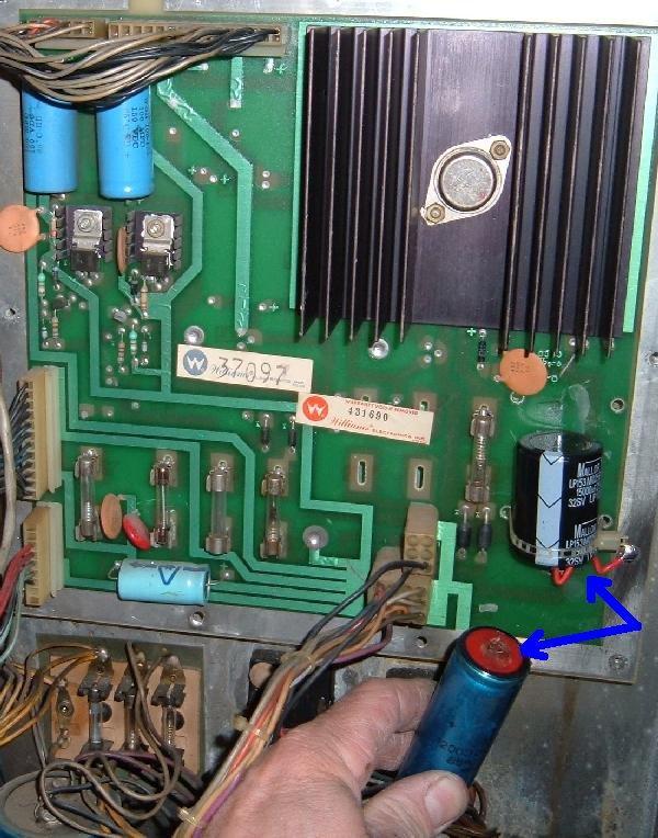
Here's a system6 power supply from a Gorgar where the original 5/12 volt filter
capacitor was bulging at the positive lead. This was replaced with a new
15,000 mfd snap cap.
|
|
Note on Williams system3 to system7 games with more than two flippers,
a higher MFD filter cap will be required! For example any Willams
system3 to system7 game with three or four flippers should have a
15,000 MFD filter capacitor. Anything less and the game will reset
if both cabinet flipper buttons are pressed at the same time.
Often many techs will measure the amount of AC voltage coming through on
the DC 5/12 volt circuit. This is done with a digital multimeter (DMM)
set to low AC volts, putting the DMM's leads on the two leads of
the 5/12 volt filter capacitor. Normally anything above .200 volts AC means the
5/12 volt filter capacitor is bad. But on system3 to system6 games,
because of the two diode half wave rectification, it is nearly impossible to
get less than .200 volts AC even with a new filter capacitor. Just keep
that in mind. On system7 games a new 15,000 MFD filter cap should put
the AC ripple at .100 to .200 volts AC, which is fine.
Note all newer capacitors (of the same
value) are smaller than the original capacitor.
Original style 15,000 or 18,000 mfd axial electrolytic capacitors are not
easy to find. An easier to find replacement, currently
available from many sources, are radial "Snap Caps".
To install one, the snap cap will
need to be siliconed (and if possible nylon tie wrapped)
to the power supply board, and have wires
going from its terminals to the power supply board. Not the cleanest
look, but it does work well. Be sure to mount the cap "flat" to the
power supply board, with the cap leads facing *down*. DO NOT
MOUNT THE CAP WITH THE LEADS FACING OUT (away from the power supply
board). Due to the vibration in pinball machines, the silicone used
to secure the cap will eventually fail if the "tall" cap is mounted
with the leads facing "out".
Another method is to use a snap cap and
drill a hole in the board for the second cap lead.
This method is NOT recommended! Again, due to vibration,
the solder leads will crack, removing the capacitor from
the circuit.
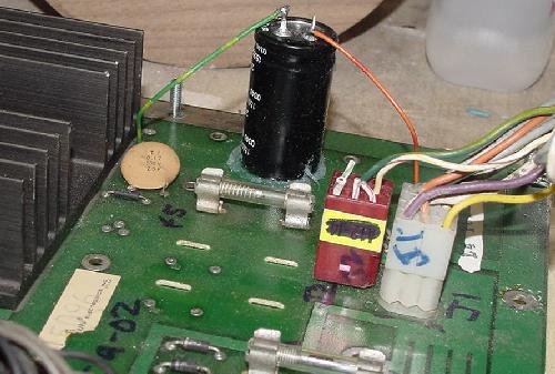
DO NOT mount a snap cap like this to the power supply board! The cap should
be mounted "flat" to the power supply instead. But note the wires running
to the board's contact points. Mount the cap flat on the board with the contacts
facing down and silicone it, instead of having it perpendicular to the board
(as shown here).
|
Upgrade 2: Add Fuses for the Lamp & Solenoid Bridges.
Adding these fuse can is a good idea, and could prevent a fire.
This applies to all System3 to System7 games.
Please see above for this information.
Upgrade 3: Replace Connector at 3J6.
(Component #10 in the "key" picture.)
Replace the header pins at connector 3J6 on the power supply.
This applies to all System3 to System7 games.
This is the +5 volt connector, and it needs to be in perfect condition.
So just replace this with new .156" header pins before even powering
the game on for the first time. It is also recommended
that the connector's terminal pins in the plastic housing also
be replaced, with new .156" Trifurcon terminal pins.
The power supply connect J6 (top right), which outputs the +5 and +12 volts
to the rest of the game. This 15 pin connector needs to be replaced, regardless
of its condition. This applies to all System3 to System7 games.
|
|
Connector J6 is of major importance. Not just because it is
the +5 logic power connector, but also because it handles
the +12 volt connection to the CPU board's reset section. There is just
*one* pin on J6 that handles this 12 volt connection. If this
pin is in bad condition, the game will not run! So it's a good idea to
just replace the entire connector 3J6, and be done with it.
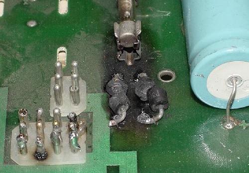
Diodes D7 and D8 on System3 to System6 power supplies. Obviously
these are a bit under-rated for this usage! Note connector J1 (12 pins)
has also taken some abuse. This connector supply power to diodes D7/D8.
|
|
Upgrade 4: Replace +5/12 volt Rectifying Diodes D7/D8.
(Component #4 in the "key" picture.)
On System3 to System6 power supplies only, the diodes at D7 and D8
need to be replaced. These two diodes rectify the AC voltage to
DC, which is ultimately used for the +12 volts and +5 volts
logic. The MR500 diodes are 3 amp diodes, but should be
replaced with 6A4 (6 amp, 400 volts) diodes, or
6A2 (6 amp, 200 volts), or even 6A50 (6 amp, 50 volts).
Radio Shack sells 6A50 diodes, part number 276-1661.
Note on System7 power supplies the AC to DC conversion circuit was
beefed up. Diodes D7 and D8 were eliminated,
and replaced with a bridge rectifier BR1. A bridge rectifier is
essentially a grouped set of four diodes.
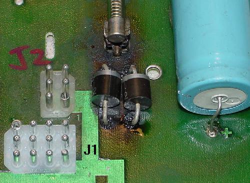
The same power supply with diodes D7 and D8 replaced with 6A4 diodes. Also
connector J1 was replaced.
|
|
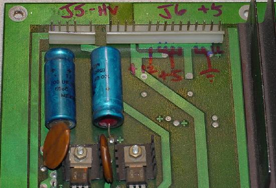
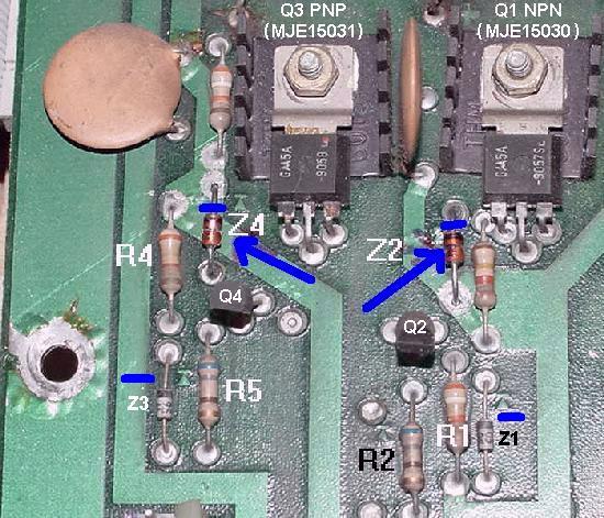
Upgrade 5: Replace Display Power Diodes Z2/Z4.
(Components #1 in the "key" picture.)
Power supply zener diodes Z2 and Z4 are 1N4764 diodes, which are 100 volt
diodes. These should be replaced with 1N4763 diodes, which are 91 volt
diodes on all System3 to System7 power supplies.
The reason for this is simple; the 91 volt diodes
increase score display life.
This decreases the score display voltage from 100 volts to 91 volts,
making the score display last a lot longer. Since score diplays are
now only made by one manufacturer, it is important to make them
last as long as possible. The downside to this modification is the
score displays will be a bit dimmer. But the added life of the displays
is worth it.
A system3 to system6 power supply and the High Voltage section. The two diodes
with the faint blue arrows next to them are Z2/Z4 (1N4763). The diode bands are
oriented with the blue lines. Also shown are resistors R2/R5 (660 ohm) and
R1/R4 (39k ohms). Note Q1 and Q3 are the high voltage transistors, and can be
replaced with MJE1503x equivalents provided the legs are crossed (as discussed
below).
|
|
Upgrade 6: Replace Power Supply Resistors R2/R5 and R1/R4.
(Components #1 in the "key" picture.)
Williams recommend upgrading resistors R2 and R5 from 680 ohms to 1.2K ohm
1/2 watt resistors for better reliability of the high voltage section.
Also it's a good idea to at least check resistors R1 and R4, 39k ohms.
Replace as needed with new 39k ohm 1 watt flameproof
resistors. This applies to all System3 to System7 power supplies.
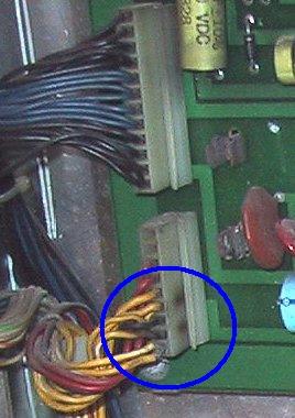
Upgrade 7: Check Connector 3J3.
(Component #7 in the "key" picture.)
This is the solenoid power connector on the power supply. Very often
this connector is brown. This will cause resistance, and weaker
coils. This applies to all System3 to System7 power supplies.
Upgrade 8: (System7) Replace the G.I. Connectors.
(Not shown in the "key" picture.)
Also also applies to the System3's Hot Tip and Lucky Seven. Basically
all System7 games will have burnt G.I. (General Illumination) connectors
on the power supply board.
More information on this is below.
Testing the Power Supply.
Before turning the game on for the first time, it is a good
idea to test the power supply. If any part of the power supply is not working,
the rest of the game is not going to work. And a damaged power supply
could damage some other component of the game. So it's best to isolate
and test the power supply first, before doing anything else.
To do this, disconnect *all* the connectors
from the power supply, except for 3J1 and 3J2 (these are the
two square connectors). J1 is a rectangle 12 pin connector, which
feeds all the input voltages to the power supply. J2 is a rectangle
6 pin connector, which feeds ground from the external bridge rectifiers.
All the other .156" straight line connectors are output connectors,
and should be removed.
Power supply components shown on a System3 to System6 power supply.
Picture by Mark.
| |
|
- The +100/-100 volt score display power supply.
- The +5volt DC regulator for the logic power supply.
- The 12,000 mfd filter capacitor for the +5 volts logic power.
- The rectifier diodes for the +5 volts logic power supply.
- The power input connectors.
The larger square Molex connector on the bottom is the power inputs
from the transformer and backbox bridge rectifiers.
The smaller square connector is the lamp/solenoid bridge rectifier ground input.
- The filter capacitor for the +28vdc solenoid power supply.
- Solenoid and Flipper power output connector.
- Lamp and Solenoid power output connector.
- Display Power +100/-100 output connector.
- Logic power output connector (+5 volts regulated and +5 volts unregulated).
- The +100/-100 rectifying diodes which convert 100 volts AC to unregulated DC.
Check the +12 volts.
With all the connectors removed except for J1 and J2,
turn the game on.
Measure the +12 volts DC with a DMM at 3J6 pin 6
(pins 11 to 15 of J6 are ground). This is unregulated 12 volts,
so it should be in the 10 volts to 14 volts DC range.
If the voltage is outside that range, most likely it is
the filter capacitor (C15 12,000 mfd at 20 volts for system3 to system6,
or C10 18,000 at 20 volts mfd for system7). This capacitor commonly fails
on these power supplies. There is more information on this
capacitor below (see the +5 Volt Logic Filter Capacitor.)
Beyond the capacitor,
on system3 to system6 games, it could be either diodes D7 or D8 (MR500,
which should have been replaced with 6A4 diodes, as discussed above).
These diodes commonly fail due to heat.
These diodes can be easily tested using a DMM set to the
diode function. Put the DMM leads on each lead of the diode, and a reading
of .4 to .6 volts should be seen in one direction, and no voltage in the other.
On system7 games, the BR1 bridge rectifier (35 amps 400 volts) could be faulty.
Lastly the problem could be the transformer (but that is unlikely). Testing
this bridge rectifier is described below in the +5 volts section.
Check the +5 Volt Logic Voltage.
The +5 volts is the power that runs all the logic circuits
on the game. If the +5 volts is not "perfect", the game will not
run at all, or will have random resets and lockups.
There are two things that make the +5 volts "perfect": voltage in the
4.9 volt DC to 5.2 volt DC range, and a nice "smooth" 5 volts.
The +5 volts is not adjustable (the power supply have components that
do this automatically).
To check the +5 volts, use a DMM and measure the +5 volts DC at
power supply connector 3J6 pins 7 to 10 (remember J6 pins 11 to 15 are ground).
The +5 volts should measure between 4.9 and 5.2 volts DC.
If the +5 volts is low at the power supply, either the connectors are
in bad shape, or the regulation circuit is probably damaged. If the voltage is
Ok at the power supply, but is later tested at the CPU board
and found to be less than 4.9 volts, the CPU board could also
have some problems that are "dragging down" the power supply. There
could also be a problem on the power supply +5 volt regulation circuit,
which fails "under load". But first check and replace the connectors
on the power supply (3J6) and the CPU board (1J2) before doing anything else.
Fixing a bad +5 volt circuit is pretty straight forward.
On System3 to System6 games, this involves
the large heat sinked X3 (LM323, 3 amp, 5 volts) voltage regulator on the power supply board,
and two diodes at D7 and D8. The voltage regulator itself is
pretty well protected and doesn't usually fail. As described
above, diodes D7/D8 do often fail though.
A shorted D7/D8 diode should blow a fuse,
an open diode causes +5V voltage to drop and prevent the game from starting.
These can be easily tested using a DMM set to the diode function. Put the DMM leads
on each lead of the diode, and a reading of .4 to .6 volts should be
seen in one direction, and no voltage in the other.
On System7 power supplies, low or no +5 volts
is either the bridge rectifier BR1,
chip IC1 (723PC), or transistor Q5 (2N6057,
which should be replaced with an easier to get 2N6059).
The bridge rectifier BR1 (35 amps 400 volts,
which is really four diodes in a metal case) is used to convert AC to DC
volts, and replaces the D7/D8 diodes on older System3-6 power supplies.
The System7 BR1 bridge can be tested. Note the positive side of the bridge
is "offset" from the other three leads, with the lug facing a different
direction than the other three lugs. The negative lug is diagonial to the
positive lug. And the two AC lugs are the two remaining lugs.
- Turn the game off.
- Put the DMM on diode setting.
- Put the black lead of the DMM on the "+" (positive) terminal of the bridge.
- Put the red lead of the DMM on either AC bridge terminal.
Between .4 and .6 volts should be seen. Switch the red DMM lead to the other AC
bridge terminal, and again .4 to .6 volts should be seen.
- Put the red lead of the DMM on the "-" (negative) terminal of the bridge.
- Put the black lead of the DMM on either AC bridge terminal.
Between .4 and .6 volts should be seen. Switch the black DMM lead to the other AC
bridge terminal, and again .4 to .6 volts should be seen.
Check the High Voltage +/-100 volts.
With all the power supply connectors still removed except for
J1 and J2, turn the game on. Put the DMM's black lead on J5 pin 1 (ground).
Put the red lead on J5 pin 3, and between -90 to -105 volts DC should be seen.
Now move the red DMM lead to J5 pin 4, and +90 to +105 volts DC should be seen.
If these value are off, the high voltage section of the power supply will
need to be rebuilt (see below).
With the connectors on,
if the score displays are dead, before repairing the High Voltage supply,
look for a small orange glow in the corner of the score displays.
If that is present, then the proper voltages are probably getting to the displays,
and the problem lies elsewhere, other than the high voltage section.
If the score displays light up, but then go dim or flicker, try replacing the
two 100 mfd 150 volt electrolytic filter capacitors in the high voltage section
(C7/C11 on System3-6, C1/C3 on System7). When those capacitors dry up and get
old, the displays can look like they are dying.
Also part of the high voltage section on the first two System3 games
(Hot Tip and Lucky Seven) is a 300 volt supply circuit.
The original design used this voltage to
provide an extra "kick" to get the score displays gas to ionize.
Hot Tip and Lucky Seven used this extra voltage, but it was deemed
unnecessary after that and dropped. If a System3 power supply has some
extra capacitors and diodes that aren't on the schematic,
this is part of the 300 volt supply.
The 300 volts was produced using two diodes
and two capacitors to triple the incoming AC voltage.
If a System3 power supply has a failed 300 volt supply, there is no need to
repair it. The two extra diodes and capacitor can be removed, and this
will not affect the score displays.
Check the Lamp Voltage.
With all the power supply connectors still removed except for
J1 and J2, turn the game on. Put the DMM's black lead on J4 pin 1 (ground).
Put the red lead on J4 pin 5 to pin 8, and between 16 to 20 volts DC should be seen.
If this voltage is missing, a fuse is probably blown, the connector is bad, or the
backbox 6BR1 bridge rectifier has failed (or the connectors going to this
bridge have come off, which is common, see below). Also note the large "can"
capacitor in the bottom of the backbox *not* mounted on the power supply is
used to smooth this lamp voltage. Sometimes this 30,000 mfd 25 volt
capacitor fails too (though this is rare).
Check the Solenoid Voltage.
With all the power supply connectors still removed except for
J1 and J2, turn the game on. Put the DMM's black lead on J3 pin 3 (ground).
Put the red lead on J3 pin 6 to pin 9, and between 28 to 38 volts DC should be seen.
If this voltage is missing, a fuse is probably blown, the connector is bad, or the
backbox 6BR2 bridge rectifier has failed (or the connectors going to this
bridge have come off, which is common, see below).
On the Power Supply board there is also a 47 volt varistor, used to protect the
solenoids from voltage spikes. There is also a 100uf filter capacitor.
The flipper voltage has a slight deviation.
On System3 and System4 games, +28 volts goes directly to the flippers from the
solenoid bridge rectifier (there is a fuse located under the
playfield). On System6 and System7 games, the flipper voltage
is goes through the Power Supply
board (but is not manipulated), with fuse F4 protecting the flipper circuit
(the under playfield fuse is now gone). On the last three System7 games (Firepower2,
LaserCue, Starlight), flipper power comes from a separate 50 volt flipper power
supply board.
The +5 Volt Logic Filter Capacitor - Replace it Now!
The last piece of the +5 volt logic puzzle, and the one that
fails often, is the filter capacitor. After the voltage is converted
from AC to DC, the voltage must be "smoothed". This is done using
a large capacitor (C10 on System7 power supplies, C15 on system3 to system6
power supplies). Originally the value of this capacitor was 12,000 mfd at 20 volt.
Filter caps are largely a mechanical device. Because of this, they
wear out! The normal life span for a filter cap is about 10 years.
Since these games are well past that age, I would highly recommend replacing
this capacitor! On system3 to system6 power supplies, it is really
important to replace it because of the lower value Williams used. System7
power supplies have less problems with this cap, but it is still a good
idea to replace it.
The capacitor can be tested, with the game on using a DMM set to
AC voltage. Put the red lead of the DMM on the positive lead of the
filter capacitor, and the black lead on the negative lead of the
cap. If an AC voltage of .300 volts AC or more is seen, the capacitor
is not smoothing the DC voltage enough, and definately needs to be replaced!
Unfortunately on system3 to system6 power supplies that use just *two* diodes
for (half wave) rectification, even with a new 5/12 volt filter cap,
never less than .200 volts AC will ever be seen. On system7 power supplies
this was change to a bridge rectifier (four diodes) for "full wave" rectification.
A new filter capacitor on system7 power supplies should not show more
than .100 volts AC.
Problems with the Backbox Mounted Bridge Rectifiers Wire Lugs.
One of the first things to check on these games is the
two bridge rectifiers mounted on the rear wall of the backbox.
These bridges are used for the solenoids and lamp matrix power.
The connectors used to attach the wires
to the terminals of these bridges are sometimes loose, causing playfield lamps to go out,
solenoids to be weak or intermittent, and fuses to blow. Tighten the
connectors with pliers and reseat them,
or just solder the wires directly onto the terminals.
Williams CPU Board System 6 Test Points and their Location.
Note there are no test points on system3 and system4 CPU boards.
- TP1 = +12 VDC unreg. (upper left)
- TP2 = NMI, +5 VDC (upper left, up and right of TP1) It should read 0 VDC when diagnostic switch SW1 is pressed.
- TP3 = Memory Protect (upper center) +5 VDC when interlock closed, 0 VDC when interlock open.
- TP4 = Blanking (left middle) +5 VDC normal operation, 0 VDC blanking (when first turned on for about 1 second).
- TP5 = IRQ (lower left of center)
- TP6 = Phi 2 (lower and left of TP5)
- TP7 = CMOS RAM B+ (lower center) +4.3 VDC when power on, +3.9 VDC when power is off. If this is low, your batteries are low.
- TP8 = RESET (lower left corner of batteries) 0 VDC for first second that power is on, +5 VDC after that.
- TP9 = +5 VDC (lower right)
- TP10 = Ground (lower right)
A Revision System6 board has a part number on the lower right corner ending
in a 6 or 6A, or something similar. If the board in question does not match the location
of the test points, or if the part number differs, it may be a system7 CPU board,
as the test point location differs (see below).
Williams CPU Board System 7 Test Points and their Location.
The system7 test points are the same as system6, but their location is different.
- TP1 = +12 VDC unreg. (upper left)
- TP2 = NMI, +5 VDC (center bottom) It should read 0 VDC when diagnostic switch SW1 is pressed.
- TP3 = Memory Protect (left center) +5 VDC when interlock closed, 0 VDC when interlock open.
- TP4 = Blanking (left bottom, just to right of batteries) +5 VDC normal operation, 0 VDC blanking (when first turned on for about 1 second).
- TP5 = IRQ (near upper right side)
- TP6 = Phi 2 (lower right side)
- TP7 = CMOS RAM B+ (just under TP3) +4.3 VDC when power on, +3.9 VDC when power is off. If this is low, your batteries are low.
- TP8 = RESET (right bottom) 0 VDC for first second that power is on, +5 VDC after that.
- TP9 = +5 VDC (lower left, just at the upper right corner of batteries)
- TP10 = Ground (lower left, next to TP9)
Remember some early Black Knight games (first system7 game) used
the early System6 power supply. This is easy to identify; if the
transformer is in the lower cabinet, it's a system7 power supply.
If the transformer is in the backbox, it's a system6 power supply.
A System7 CPU board has identical test point values to a
System6 board, but the test points are in different locations.
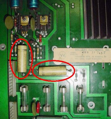
The additional power supply .22mfd caps only needed for Hot Tip
and Lucky Seven. Pic by Karonhalt.
|
|
Additional Power Supply Parts on System3 Hot Tip/Lucky Seven.
The first two system3 games (Hot Tip and Lucky Seven) had two additional
capacitors and diodes compared to the later system3 to system6 power supplies.
These were used for the 300 volt feed for the display driver.
These parts were dropped starting with World Cup (the third System3 game).
Unless there is a specific problem with the display drive on these two
games, the two 1N4001 diodes and two .22 mfd capacitors do not need to be replaced or
checked (the capacitors are actually not electrolytics, but are "MKP" caps).
They can even be removed entirely from the power supply if used in
later system3 to system6 games.
A system3 to system6 power supply and the High Voltage section. The two diodes
with the faint blue arrows next to them are Z2/Z4 (1N4763). The diode bands are
oriented with the blue lines. Also shown are resistors R2/R5 (660 ohm) and
R1/R4 (39k ohms). Note Q1 and Q3 are the high voltage transistors, and can be
replaced with MJE1503x equivalents provided the legs are crossed (as discussed
below).
| |
|
Rebuilding the +/- 100 volt High Voltage Section.
Williams used two different types of transistors, and slightly different
circuitry routing, for the display power supply circuitry
on their games from 1977 through 1989.
Commonly Defective System3 to System6 High Voltage Parts:
- Q1 = MJE15030* (NTE54) - replaces the original SDS-201 (NTE171).
- Q3 = MJE15031* (NTE55) - replaces the original SDS-202 (NTE296).
- Q2 = MPSD52 (NTE288, 2N5400, or 2N5401).
- Q4 = MPSD02 (NTE287, MPS-A06, or MPS-A42).
- Z2,Z4 = 1N4763 (91 volt) zener diodes - replaces the original 1N4764 (100 volt) diodes.
- Z1,Z3 = 1N4730 (3.9 volt 1 watt) zener diodes - replaces the original 1N5990 (3.9 volt 1/2 watt).
- R2,R5 = 1.2k ohm 1/2 watt resistors - replaces the original 680 ohm 1/2 watt resistor.
- R1,R4 = replace with 39k ohm 2 watt - replaces the original 1/2 watt version.
- C7,C11 (C1,C3 on System7)= 100 mfd 150 volt electrolytic capacitors.
* Note that the original style SDS201/SDS202 transistors at Q1/Q3 are no longer
available in any flavor or form. These two transistors must be replaced with
the newer MJE15030/MJE15031 transistors. BUT NOTE: the MJE transistors had a
different pinout than the original SDS transistors, so they must
be installed differently on the board!!
Pinouts:
- SDS trans: E B C
- MJE trans: B C E
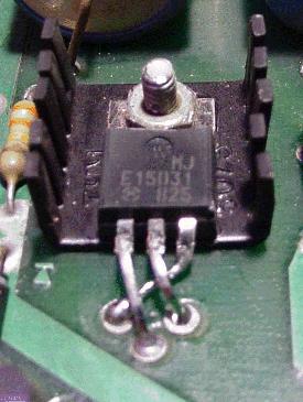
A replacement MJE15031 in an older System6
power supply. The leads on the MJE15030 and
MJE15031 must be "twisted" to replace the
older SDS201 and SDS202 transistors.
IMPORTANT: heat shrink tubing should be
installed over the crossed leg to prevent
shorts!
|
|
The MJE transistors can also be installed without any board moficiations,
but this can be a bit difficult.
The left two legs must be installed in the 2nd and 3rd holes, respectively
(as described above), and the rightmost leg will then
criss-cross under the first two legs, and install in the 1st hole.
This is actually the way Williams
recommended doing it in their service bulletin.
It is recommened that some heat shrink tubing be installed on the rightmost
leg to prevent any arcing or shorts to the other legs.
2d. Before Turning the Game On: Batteries, the Battery Holder,
Battery Corrosion, and the 5101 RAM.
How old are those batteries in that game?
If an answer can not be determined, it's time to change them!
Besides dead batteries, CPU board battery corrosion and/or
a bad IC19 CMOS 5101 RAM can cause
some problems too. This section talks about these problems.
The problem with old batteries is leakage. If the batteries leak, they
will leak corrosive material over the CPU and driver board! Also the
corrosive fumes from the batteries alone can corrode the ROM sockets and
the 40 pin inter-board connector. This is cause random game lock ups
and resets, game boots into audit mode,
or make the game not work at all.
Isn't Battery Corrosion Obvious?
The short answer is, "no!" Batteries can leak corrosive fumes,
which may not corrode the circuit board. But these fumes can corrode
sockets and header pins without it being obvious.
If these pins get even gray, it can increase the resistance of the pin,
or make the pin not conduct at all. It can even make an internal socket
pin break, which may not be seen by the naked eye.
And this in turn can make a game not work. Any grey/green pins of a socket or header pin
is probably from leaking battery fumes.
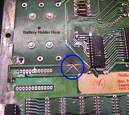
Battery corrosion on a sys3/4 cpu board just under the battery holder shorted address
line A10 to chip select CS1. This short made the CPU board not boot.
Picture by Jerry.
|
|
Game Comes up in Audit Mode.
Booting into Audit Mode Explained.
On system4 to system7 pinballs all the game's options and audits are
stored in CMOS memory (system3 is a bit different, and is explained below).
If the batteries are dead, or the battery holder is damaged,
or the blocking diode D17 has failed, or there's a bad IC19 RAM 5101 chip,
or battery corrosion has
damaged the CPU board, the game will power up into "audit mode".
Audit mode is shown in the picture above, and is saying that
the game has lost its CMOS memory, and there's a problem.
It's a big red flag when the game is turned on, since the game
goes into audit mode instead of attract mode (game over mode).
Operator assistance required!
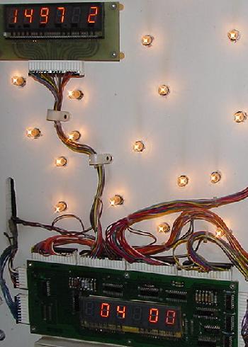
AUDIT MODE:
On system4 to system7 games, the dreaded audit mode.
A Firepower powered-on with dead batteries and/or a
dead IC19 5101 RAM chip, booting into audit mode.
Audit "00" shows the game number (#497) in the
player one score display, the operating system revision
(the preceding "1", meaning "green" flipper ROMs, where
"blue" flipper ROMs have a "2", and yellow flipper ROMs
have a "0"), and the software revision (version "2")
next to the game number. The "00" in the ball-in-play displays
shows audits number zero, and "04" in the credit window
indicates audits (remember "01" is lamp test, "02" is
solenoid test, and "03" is switch test).
|
|
In audit mode ("04 00" in the credit/ball-in-play display, where "04"
is audits, and "00" is the first audit number),
the numbers shown in the player1 score display are the value
for the audit number shown in the ball-in-play display.
For audit "00", which is the software identification
audit, the last number is the game's current software
revision number (version 2 in the above picture).
The middle three numbers are the game number
(i.e. 497 is Firepower; see the
Game List section for all the
game titles and game numbers).
And the first number determines the "flipper ROMs"
version installed. Remember Williams used a color coded system:
- 0 = Yellow Flipper ROMs (system4)
- 1 = Green Flipper ROMs (system6)
- 2 = Blue Flipper ROMs (system7)
These software identification numbers made it easy to see if the
wrong Game and/or Flipper ROM software was installed in the machine.
Note the lack of a code above for White flipper ROMs (system3).
This is because the boot-up "software revision" mode was not implemented until
System4 and the Yellow flipper ROMs, when adjustment were also
stored in memory (system3 used DIP switches for the adjustments,
which are read by the CPU board at boot up).
Williams did the audit mode routine to show instantly upon power-on
that the game's adjustments/audits were lost, and that the batteries needed
to be replaced. The main reason this was done was to protect
the game from having garbage in an adjustment that may put
the game into free play (or some other equally accidental
bad mode), since now all the game's adjustments were stored in memory
instead of being "hardcoded" with DIP switches.
With system6 and its memory protection circuit/coin door switch,
it also keep miscreants from drilling
through the bottom of the game and activating the switches to change the
settings (like one quarter equals 25 credits!), since the coin door
now had to be open to change an adjustment/audits.
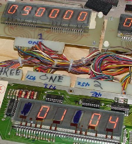
A system3 game (Hot Tip) with dead batteries booting into audit mode.
Here the audit number is in the credit window ("01"), the audit mode ("04")
is in the ball-in-play window, and the value for the first audit ("090000")
is in the player1 score window.
|
|
System3 and its Audit Mode.
On system3 games, a dead battery or failed CMOS memory still
comes up in audit mode, but there is no indication of software revisions.
The audits in system3's white flipper ROMs looks a bit different too,
with the audit number in the credit window, and the "04" (to signify audits)
in the ball-in-play/match window (this was reverse of system4 to system7),
and the audit value in the player1 score display. If the manual-down/auto-up
switch is in the auto-up position, the game rotates through all the audit
numbers automatically also. Because of this, system3's audit mode has
a different look and feel then its later system4 to system7 cousins.
Battery Holder Woes.
Also bad batteries can rot the existing battery holder. If the
batteries do not make good contact to the battery holder (or
the batteries are dead!), the
game will always turn on in "audit" mode. This is indicated by
one number, a space, and then four numbers, in the player one score display
at power on.
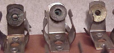
A bad battery holder. At first glance, this holder looks fine.
But the two battery contact points on the left have corroded
and fallen off. The contact on the right is the only one intact.
These contact points are actually rivets, but corrosion will
cause the face of the rivet to break as it goes through the
fiber insulator, and the face of the rivet that contacts the
battery falls off.
|
|
When replacing the battery holder, the best variety is the new
Williams WPC-S and later black plastic battery holder, part number A-15814
(Pinball Resource sells these).
Always Check Diode D17: Checking the Battery Voltage and D17 Diode.
I find the blocking diode D17 should be checked on all system3-7 CPU boards.
This diode prevents the +5 volts rail from trying to charge the AA batteries
when the game is on, and also from trying to power the whole CPU board
when the game is off (instead of just the 5101 RAM chip).
I find this diode bad quite often (about 20% of the time),
especially on system6 CPU boards.
On the non-banded side of diode D17, the battery voltage
in reference to ground should be about 4.4 to 4.8 volts DC. On the banded side of
diode D17, it should be about .5 volt less, or 3.9 to 4.3 volts DC.
After the battery holder is replaced, install new good quality batteries.
Using a DMM, then measure the voltage right at the RAM chip IC19 (5101 CMOS RAM),
pin 22 (and pin 8, which is ground).
This should show about 3.9 to 4.3 volts DC.
On System6 and System7 CPU board, this voltage is also at test point 7.
If there is not 4 volts at IC19 pin 22, check the
voltage at the blocking diode D17.
If there is no voltage on the banded
side of D17, but there is voltage on the non-banded side, replace this diode
with a new 1N4148 or 1N914 diode.
If there is no voltage on the non-banded side of diode D17, then the
batteries or battery holder is at fault.
Also check for voltage at the CPU chip IC1 pin 8 (+5 volts pin)
with the game off. If voltage is found, the D17 diode is
shorted allowing the battery to
power the entire CPU when the game is off. This will drain batteries in a
few days. Also if this happens, the CPU board will try to
charge the batteries when the game is turned on. Alkaline batteries are
obviously not designed for this, and will get hot, and probably leak.
If batteries are not installed in the CPU board, diode D17 can also be tested
with a DMM on the diode setting. Put the black DMM lead on the banded
side of the diode D17, and the red lead on the non-banded side. The DMM
should read .4 to .6 volts. Reverse the DMM leads, and a null reading
should be seen.
Check 5101 RAM IC19 pin 22 for Battery Voltage.
Ultimately the power from the battery ends up at the 5101 RAM (IC19)
at pin 22 (bottom left pin of the chip, opposite pin 1). If the batteries
are new, you should get around 4 volts at this pin. Note there is a
slight voltage drop if you measure the voltage at the battery holder
compared to IC19 pin 22.
This happens because of the D17 blocking diode (which prevents the MPU
board from trying to charge the batteries when the game is powered on).
If IC19 pin 22 is less than 3.6 volts DC, the game will boot into
"audit mode". This happens because the batteries are
dead, or the battery holder is bad, or the D17 blocking diode is bad,
or there is a broken circuit board trace, or the IC19 RAM socket is bad.
Batteries Ok but Still Powers-up in Audit Mode.
If the batteries are good, and there is at least 3.9 volts DC
getting to the 5101 RAM chip at IC19 pin 22, chances are about 99% the
5101 RAM chip at IC19 has failed if the game comes up in audit mode.
Also be aware sometimes these board are sometimes picky about their 5101.
That is, one 5101 that worked in another system3-7 board (or a Bally MPU) may not
work in the suspect board - it may require you to try several different 5101
RAM chips at IC19 to get the board out of audit mode.
Keep in mind there are two other chips involved in the memory protect circuit on sys6/7.
On system6 that's IC27 (4071 CMOS) and IC12 (7808), and
system7 that's IC10 (4071 CMOS) and IC12 (7808). But frankly it is
very rare that either of these chips fail. More likely again it's the
5101 at IC19. Keep in mind on system3/4 there really is no memory protect circuit
per se, but IC12 (7808) can fail causing a continual audit mode boot.
On all System3-7 games, if the game boots into "audit" mode,
try this: Turn the game on, allowing it to boot into audits.
Then flick the power switch off/on quickly.
This should put the game into game-over "attract" mode
(on sys6 and sys7 games with a coin door switch, the coin door needs to be open
for this to work). This won't fix
a failed 5101 ram chip or dead batteries, but it usually allows the game to be played in
the short run. If the game still won't come up in attract mode
with this trick, the 5101 RAM at IC19 is *really* dead, or the memory
protect circuit has fail (IC12 or IC27/IC10). Note that this trick
does not work as well on system7 games.
Another trick on System7 games (only)
if the game boots into audit mode, is to try advancing through
the audits/adjustments with the Advance button inside coin door. After
the audits get to number 50 or so, it will pause, and reset the game to "game over"
(attract) mode. If it doesn't come back to attract mode, but goes to audits
("04") again, try the Advance button again to move the audits past number
50 or so. If it can't get
into attract (game over) mode, then there may be a bad resistor
DIP network in the memory protect circuitry, in addition to a bad 5101 RAM.
Note System3 to System6 did not use DIP resistor
networks, and the audit would never go into attract mode (they just wrap
around, back to zero, except on World Cup).
In addition on system7 games, I've seen a bad EPROM at IC14 cause the
game to never get out of audit mode. The game boots into audits, but
even with a good battery and 3 volts at the 5101 pin 22, it just won't get out of audits.
This problem once drove me crazy until I figured it out!
Using the Internal Diagnostics to Test the 5101 RAM.
Another method to test the 5101 RAM at IC19 is to use the built-in
firmware diagnostics. Note this requires the game to "boot" into audit
mode (or attract mode) at minimum. After the game has booted, press the
lower diagnostic button on the CPU board (with the coin door open).
Note what happens to the two LEDs on the CPU board.
If on a system3 to system6 CPU board
both of the two LEDs stays on, then the 5101 RAM at IC19 is
dead for sure, and will need to be replaced. On system7, if
"8" or "9" is displayed on the 7-segment LED, also 5101 RAM is also
probably dead. If the 5101 ram is good, often you'll see a "6" on
the display instead.
CR2032 Coin Battery.
Personally I've really moved to using a cr2032 coin battery and holder
on sys3-7 cpu board. These lithium batteries don't leak (providing
the blocking diode has not failed!) and they are inexpensive. They don't
last a really long time (usually two years.) Also you can *not* use
a cr2032 battery if you have an AMI branded 5101 chip. Why? Because
these crappy AMI rams are too power hungry, and they will kill the
cr2032 in about one month. I don't see this as a problem myself,
because whenever I see an AMI branded chip (being it 5101, 6821 PIA,
6800 or 6802/8 processor), I always change it out. The AMI branded
chips, in the long haul, have proved to be very problematic. Basically
they are "junk" at this point in time... At least this has been
my experience.
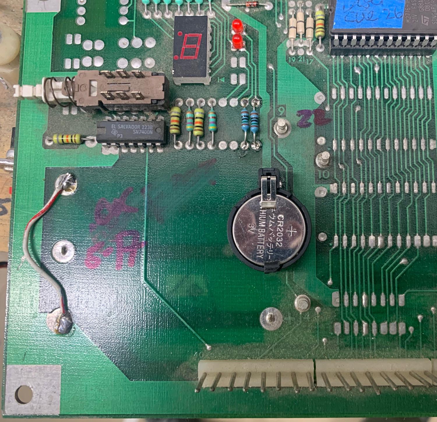
Using an inexpensive CR2032 battery and holder on a system6 MPU board.
Notice the changed 5101 ram to a new Phillip PCD chip. Highly recommended
as the Phillips branded ram is very low power consumption, and will allow
the cr2032 to last longer.

Using an inexpensive CR2032 battery and holder on a system7 MPU board.
|
Remote AA Battery Holder.
If you insist on using AA batteries, they MUST be remote mounted!
On system3 to system7 games, I can't stress this enough!
Get the AA batteries OFF the mpu board and mount them remotely.
Again I really don't recommend AA batteries, the cr2032 alternative
seems like a no-brainer to me. But if you must use AA, remote mount them.
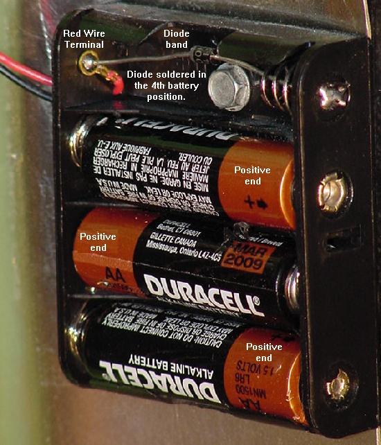
Personally I buy an inexpensive battery holder, put a 1N4004
diode in it (as a backup blocking diode), and mount it on the
inside wall of the backbox. This way if the batteries corrode,
it only ruins a cheap battery holder (and doesn't cause
MPU/driver board corrosion, and ruin the 40 pin interconnector).
Though the diode is not needed, I like to use it because it lowers
the battery voltage slightly. This means the game will show the
batteries as "dead" sooner (alerting me to change the batteries
before they leak!)
Using an inexpensive four AA battery holder, a 1N4004 blocking diode, and
three AA batteries as a remote battery holder for the MPU board.
|
NVRAM usage.
A lot of people are moving to NVram. The NV means "non-volatile".
Basically it's a ram chip that replaces the 5101, and requires
*no* battery. This is a good solution too, as you no longer have
to use any sort of batteries. The only downside is that the 5101 ram
on original sys3-7 cpu boards are soldered in place. So you will have to remove
the original 5101 ram chip, and install a socket. Only then can you
use an NVram.
2e. Before Turning the Game On:
40 Pin Interboard Connector (Dead Game or Random Lockups & Resets)
The majority of these machines are over 20 years old
and have seen years of hard use.
Dirt, heat, cold, moisture and smoke have taken their toll on
the machine's connectors. Conditions and temperature
changes, which result in expansion and contraction of the solder joints,
leading to microscopic cracks in solder joints. This can cause
a pinball to lock up during play, locking on coils (which in
turn can kill the driver transistor and possibily the solenoid PIA),
or to not start at all at power-on.
If the user of the System3 to System7 game in question wants
a good, dependable, working pinball, ALL of these following
connector issues must be addressed!
Inter-Board Connector Woes.
If experiencing intermittent
problems with a machine, the most common part to suspect are the
printed circuit board connectors. For example, lets say every
fourth time the machine is turned on it locks up with the two CPU LEDs on.
Chances are at least one of the problems is the 40 pin interboard
connector, attaching the CPU and Driver boards together.
As Mark O. puts it, "if 95% of all intermittent problems are caused by connectors
in general, then 95% of connector problems lie in the 40 pin inter-board connector
which joins the driver and CPU boards together."
The 40 pin inter-board connector on a System6a CPU and Driver board.
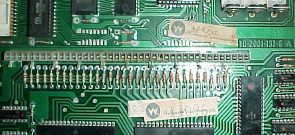
|
In previous sections we discussed the reasoning behind the split board design,
separating the components for easier field maintenance. But the Achilles heal of
this design is the 40 pin inter-board connection. Williams' designers opted to move the
entire data bus (8 lines) and address bus (15 lines) over these pins, as well as the reset,
blanking, interrupt and every other critical system signal.
This is unlike the other non-interboard connectors, which are
lamp, switch and solenoid related. These connectors are far less
critical, and won't lock the CPU if disconnected for a short moment.
The inter-board connector worked well for the first
few years of a machine's life, but after years
of service, connectors would start to fail.
Besides getting dirty, the solder joints on both boards would develop
microscopic cracks due to vibration, heat and humidity changes.
If this caused one micro-second of a disconnect in a data or address line,
that would be enough to lock the machine.
To make matters worse, on system3 to System7 games, the batteries
are located right above the 40 pin inter-board connector! If the
batteries leak they will damage this connector for certain.
Another little known fact is these .156" Molex connectors
have a lifespan of only 25 cycles! That means after a connector has been
installed and removed a number of times, the female and male connector
pins are essentially worn out. Add to this time
(again, these games are 20+ years old), environment and vibration,
and the cycle life is probably well below the 25 cycle spec. This compromises
the "gas tight" seal between the female and male pins, allowing corrosion,
and hence intermittent connections. Between the female pins loosing
tension and the plating on the male pins
wearing from inserting and removing the connectors, they are just worn out.
Now the only solution is to replace the connector pins to regain
reliability.
Comparison of the new style male square header pins
and the original round pins.
|
Replace the Female pins on the 40 Pin Interboard Connector.
Frankly connector replacement is the ONLY solution to a reliable game. Before even turning
on one of these 20 year old machines, replace the female
side of the 40 pin inter-board connectors. These are cheap parts, and
replacement ensures the machine will operate reliably. Some repair people will
recommend just resoldering the header pins or reseating the boards. This is not
the long term solution! Heck it's not any kind of a solution.
The tension on the female pins is gone after
20 years of use, and replacement of the
female pins is the only choice.
Replacing the male .156" header pins is usually not needed, and not
recommended unless the old pins are corroded. Usually a small
wire brush on the pins will fix them up nicely. (I buy a small wire brush
with steel wires, not brass, in the welding department of Home Depot for $2.)
Run the wire brush across the male pins to clean them up. Also the solder
joints for the male pins will often crack on the back side of the CPU board.
So those get the old solder sucked off (using a de-solderpult), and then
resoldered with new solder. (Just resoldering without removing the old solder
doesn't work too well here.) Again I use the wire brush when done to get
all the solder flux off and to make sure I haven't jumped two adjacent pins
with solder (which will cause your CPU board to not run!)
Replace the original male pins? Generally I don't do this unless
there has been battery corrosion.
Today new male header pins (if you need them) are now square,
replacing the old style round male header pins. This increases male-to-female pin
surface area, resulting in a better, more reliable connection.
That's the good news. But the bad news is the new .156" male header pins are
shorter than the original round male pins, and hence this is why it's
not such a good idea to replace the originals. Though the new square .156" male
headers will work, I would recommend not replacing them unless really
needed (like say they are corroded by battery damage).
Note an extra long variety of this .156" male connector are available from
Great Plains Electronics,
Molex part number 10-01-2270. This is an *excellent* substitution.
Another trick if you don't have the extra long male header
pins is to use the standard length .156" males. But don't
solder them with the pins all the way into the circuit
board hole. Solder the pins with just barely a touch of the tip
showing through the back of the board. After all the pins are
soldered in place, take a flat blade screwdriver, and from the
component side of the board and with the board laying flat on a workbench,
press the plastic housing down against the board.
Doing this will give the pins another 1/8" of length, which is plenty.
This picture shows the pin length difference between new and original male pins.
|
"But I Re-Seated the CPU and Driver boards, and Now My Game Works..."
If re-seating this 40 pin connector causes a game to "work", this
is a BIG RED FLAG that there's a problem. Re-seating is NOT a fix.
It just identifies a problem. The only way to fix the problem
is to replace the interboard connector. If after
re-seating the game works, this means the gas tight
seal provided by the socket or connector is gone. And the only way
to fix this is to replace the connector. Trust me, this connector
needs to be replaced!
Replacement female pins for the interconnector. This is
the 10 pin version.
|
Inter-Board Connector Replacements.
The male header pins used on the CPU board are standard .156" Molex
26-48-1241 (or 26-48-1101) 10 pin, no lock.
The originals used were the longer 26-48-7081 (8 pin) or 26-48-7101 (10 pin)
variety, but these are no longer available. Hence the 26-48-1241 pins
(which are plenty long enough) should be used.
Or use the extra long connector available from
Great Plains Electronics,
Molex part number 10-01-2270. This newer style pins
are *square* (not round), which give a much better contact surface
area to the female partion. This is very important, as the original
round style of male pin was good and cheap for the manufacturer,
but does not provide nearly the contact surface area that the newer
square style male pins provide. So unless you really need to change
the male pins, try and use the originals if possible (due to replacement
pin length issues).
Usually a small wire brush on the male pins will fix them up nicely.
Another trick if you don't have the extra long male header
pins is to use the standard length .156" males. But don't
solder them with the pins all the way into the circuit
board hole. Solder the pins with just barely a touch of the tip
showing through the back of the board. After all the pins are
soldered in place, take a flat blade screwdriver, and from the
component side of the board and with the board laying flat on a workbench,
press the plastic housing down against the board.
Doing this will give the pins another 1/8" of length, which is plenty.
The female, bottom entry board connector Molex #09-62-6104 or 09-52-3102 (10 pin)
on the driver board is a bit more obscure (but available). Williams originally used
five 8-pin connector sections (for a total of 40 pins). I personally
find it is more economical to use four 10-pin connector sections
when replacing the inter-board connectors.
Inter-Board Connector Part Numbers.
.156" male Molex Connector Pins and Female bottom entry connectors.
These are used for the 40 pin inter-board connectors. I am suggesting (four) 10 pin
sections, because economically it is cheaper (the factory used five 8 pin connectors).
However some retailers may only sell the 8 pin version.
- .156" header pins with no lock (10 pins), part# 26-48-1241 or 26-48-1101. These are
slightly shorter than the original male pins, but they work fine. The original
long pin style Molex pin 26-48-7081 (8 pin) or 26-48-7101 (10 pin)
are no longer available.
Extra long male connectors are available from
Great Plains Electronics,
Molex part number 10-01-2270.
Four 10 pin connectors needed per game for the inter-board connector replacement,
or five 8 pin connectors. I don't suggest replacing the male pins unless the
originals are broken or corroded.
- .156" PC board bottom entry connector (10 pins, tin) series 2145B,
part# 09-62-6104 or 09-52-3102 (10 pin). Available from Force/Heilind Electronics (877-588-9071)
or Great Plains Electronics or Pinball Resource (8 pins).
Four 10 pin connectors needed per game for the inter-board connector replacement,
or five 8 pin connectors.
- Also can be used: .156" PC board bottom entry connector (10 pins, tin)
series 5145B, part# 26-01-1108. This is the original replacement part,
but seems to be discontinued by Molex.
Removing (Desoldering) the Old Female Connector Pins.
Removing the old connectors from the Driver board is nothing
too difficult (assuming you have done board-leve desoldering
work before, and have the proper tools). I recommend visiting
the Beginning Circuit Board Repair website
for more information on desoldering and soldering.
The trick is on the female portion of the 40 pin connector. Because the
plastic housing keeps all the pins together, it can be challanging to
remove. A tip that Vincent suggested is to use a utility knife to cut
the plastic housing, one pin at a time (see pictures below). This works
pretty well because then the plastic housing can be easily removed.
Then the pin can be heated with a soldering iron, and removed. Finally
the pin's hole can be "solder sucked" clean, leaving a nice solder-free
hole for the new female connector.
Using a utility knife to cut the plastic female connector.
Picture by Vincent.
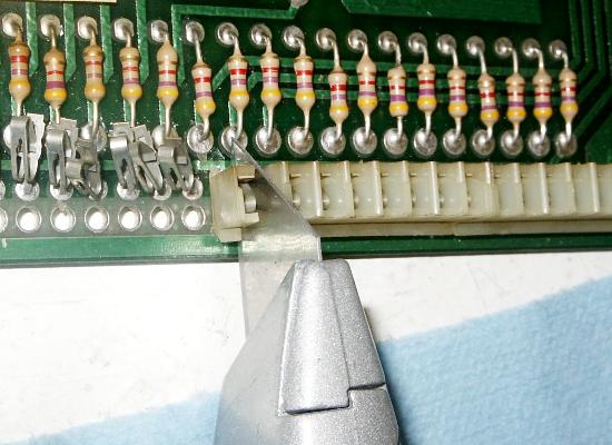
|
After the cut plastic is removed, the female connector pin can be easily
removed with a soldering iron. Picture by Vincent.
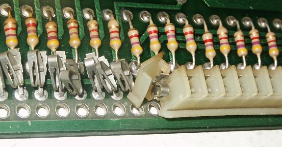
|
But aside from that, there are a couple tricks and cautions that
should be mentioned. First, use a good quality (de)soldering station
or Soldapullt tool.
There are a total of 80 pin to be removed (assuming both the CPU and
Driver board connectors are replaced), so don't mess around with
solder wick. Also the two outside pins on each board (pins 1,2 and
pins 39,40) will be the most difficult to desolder. This happens because
these pairs of pins are connected together (they are ground and +5 volts lines),
and hence they have larger solder pads and more solder on them. This
will dissipate the (de)soldering iron's heat very easily, making them
more difficult to get to a high enough temperature to desolder. Just
keep that in mind, as more heat may be needed for desoldering these pins.
Double Soldering the Male Pins.
An optional trick to ensuring good male pin connectivity and reliability on the CPU board
is called "double soldering". First, solder-suck the old solder off
the CPU board for the male 40 pins (on the solder side of the board).
Sometimes adding some new solder first will aid in the desoldering process.
Lifting the plastic housing on the male pins, so they can be "double soldered"
from both sides of the CPU board.
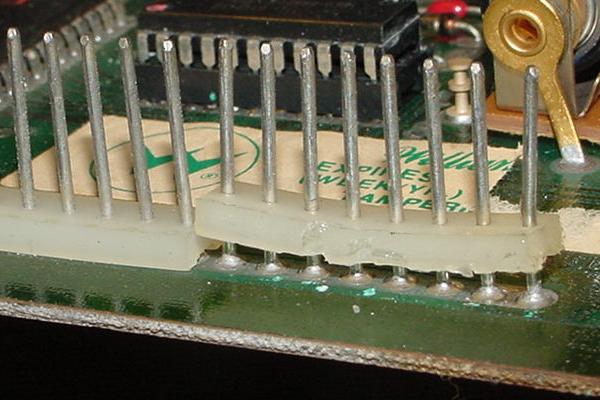
|
With the connector hanging over the edge of a work
surface, use a rubber mallet and gently hammer the pins down thru the CPU until they protrude about
1/2 inch out the bottom (solder side) of the CPU board. Then lift the male connectors
back up to their "stock" position. What this does is move the plastic
housing around the male pins further up the pins.
Now comes the "double solder" part.
On the top of the CPU board, solder under the plastic connector and
solder the pins to the pads on the top (component) side of the CPU board.
Also solder the male pins on the solder (bottom) side of the CPU board.
Now push the plastic housing back down as far as it will go.
This "double soldering" gives a much more reliable connection for the male
header pins to the CPU board.
2f. Before Turning the Game On:
Power Connectors (Dead Game or Random Lockups & Resets)
If 95% of the connector problems lie with the interboard connector,
the other 5% lie in the power connectors!
The logic bus connectors supply +5 volts, ground,
and unregulated 12 volts (called "unregulated 5 volts" by Williams once
it hits the CPU board)
from the power supply to the CPU/driver board.
This includes two .156" Molex single line connectors, one on
the CPU board (1J2), and one on the power supply board (3J6).
Both of these connectors male headers
should be replaced, along with it associated connector housing pins
(be sure to replace with "trifurcon" terminal pins).
Again, like the 40 pin inter-board connector, there really is no exception
to this rule. The 1J2 CPU connector and 3J6 power supply connector
supplies the logic current that runs the
game. The most common problem is the 12 volt
unregulated power (unregulated 5 volts after a zener diode on the CPU board).
There is only ONE pin per connector handling this
voltage (unlike the +5 volts and ground, which have a minimum of three pins each).
If this single 12 volt pin fails (and it will fail!), the game can lock up randomly,
or not run at all.
A System6a CPU board showing the 1J2 Logic Power Bus input connector.
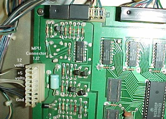
|
CPU Power Connectors 1J2.
The CPU board connector 1J2 is a nine pin .156" header male connector.
The originals use round pins. Be sure to replace with the newer square pin
variety. In the plastic housing use new .156" Trifurcon terminal pins.
This applies to all System3 to System7 games.
On Firepower and later games, replace the original IDC connector
terminal pins and
housing with new crimp-on trifurcon connector pins and plastic housing.
A System6 power supply board showing the 3J6 Logic Power Bus output
connector.
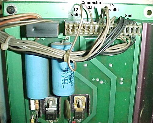
|
Power Supply Connector 3J6.
Replace the header pins at connector 3J6 on the power supply.
The power supply board connector 3J6 is a 15 pin .156" header style.
This applies to all System3 to System7 games.
This is the +5 volt connector, and it needs to be in perfect condition.
So just replace this with new .156" header pins before even powering
the game on for the first time. In the plastic housing use
new .156" Trifurcon terminal pins.
Again on Firepower and later games,
replace the original IDC connector terminal pins and
housing with new crimp-on trifurcon connector pins and plastic housing.
This picture shows where to press with a small screwdriver to
release a terminal pin from the plastic housing..
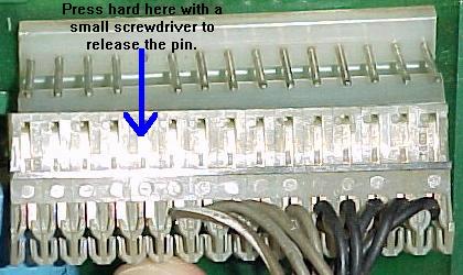
|
Crimp-On Connector Pins versus IDC.
Always replace the connector pins with a crimp-on style pin. Never
use IDC (Insulation Displacement Connector) pins.
Be sure to buy a hand crimping tool like the
Molex WHT-1921 (part# 11-01-0015), Molex part# 63811-1000,
Amp 725, or Radio Shack #64-410.
Most System3 to System6 games used crimp-on connectors. But with
Firepower, Williams changed to IDC (Insulation Displacement Connector) style
connectors. These connectors are excellent for production, but are
*terrible* in the long run. If replacing connectors on a Firepower or later game,
always replace these with crimp-on Trifurcon connector terminal
pins (a new plastic connector housing will also be required to replace
the IDC connector housing).
The crimp-on plastic connector housings can be reused when replacing
the terminal pins. Unfortunately
the IDC plastic housings can not be adapted to use crimp-on pins,
and the IDC housings must be replaced with crimp-on housings.
To remove the old connector terminal pins,
on the sides of the connectors
are slots with small metal "tabs". Press these down with a small
screw driver, and the wires/pins should pull out easily from the housing.
Do one pin at a time, and replace the pin with a brand new Trifurcon
crimp-on .156" terminal pin. Do *not* replace with the Insulation Displacement
Connector (IDC) style terminal pin! Only use crimp-on Trifurcon pins,
as documented below.
More info on pinball connectors, how to crimp, why IDC is bad, and other
pinball related connector information is avaialble at
pinrepair.com/connect.
Check the Other Connectors.
While the boards are removed, check the other connectors too.
Chances are at least some male header pins on at least one of the
circuit boards will be either tarnished or mangled. Again,
don't skimp here! Just replace them. And remember, ALWAYS
replace BOTH the male and female connector pins! There is
no short cut here. If one is bad, the other surely is too.
Non Inter-Board Connector Part Numbers.
.156" Male Molex Connector Pins and Housing.
These are used for the non-interboard connectors (such
as the power, lamp and switch matrix, and solenoid plugs), and
can be cut to the number of pins needed. I buy the header pins
and white plastic housings in a single long length,
and cut it to size. Below are the
exact part numbers for the number of pins needed.
- .156" header pins with lock (9 pins), part# 26-48-1095 (Mouser).
- .156" header pins with lock (12 pins), part# 26-48-1125 (Mouser).
- .156" header pins with lock (15 pins), part# 26-48-1155 (Mouser).
- .156" Trifurcon pins (three wipers): Molex part# 08-52-0113 (tin
plated phosphor bronze) or 08-50-0189 (tin plated brass), for 18 to 20
guage wire. Digikey part# WM2313-ND. Mouser and Competitive
Products (#06-2186) also sell these.
- .156" white housings (9 pins), part# 09-50-3091 (Mouser)
- .156" white housings (12 pins), part# 09-50-3121 (Mouser)
- .156" white housings (15 pins), part# 09-50-3151 (Mouser)
Polarized Pegs.
A polarized peg is a small nylon plug that goes into the connector
housing so the housing is "keyed" (plugging it into the wrong
board header pin connector is impossible). It is highly recommended to use these when
replacing a connector housing.
- .156" polarized peg, part# 15-04-0220 (Mouser).
Burnt General Illumination Power Supply Plugs.
On early system3 (Hot Tip/Lucky7) and all
system7 games, there are GI (general illumination)
plugs on the power supply (like 3J9 on system7).
These GI connectors will most likely need to be replaced.
Please see the GI Connectors
section of this document for help with that.
Resoldering Board Header Pins.
If the game in question is to be really reliable, certainly
the inter-board connector pins will need to be replaced.
But if the parts are not available, or a "quickie" repair
is needed, sometimes just resoldering the pins can fix
some problems quickly. Also the other non inter-board connectors
often do not need to be replaced (but do need to be resoldered).
As described above, insertion, vibration, temperature and humidity can
cause microscopic cracks in the header pin's solder joints. This can
cause the CPU board to lock up randomly. A quick solution
is to resolder the header pins.
The first trick in doing a proper resolder job is to REMOVE THE OLD
SOLDER! Now this may sound really anal, but it must be done.
The old solder is often flawed with corrosion, dirt and other crud.
If the old solder is just reflowed, often a solder "donut" will appear around
the connector pin, where the old solder (or even newly added solder)
just will not stick to the pin.
Because of this, use the desoldering method of your choice (see
pinrepair.com/begin), and
remove the old solder. Then solder with fresh new solder. The
rosin flux in the new solder is often the added ingredient needed
to make the new solder really stick to the old header pins. Be careful
when soldering so adjacent pins are not "bridged" and
shorted together.
Removing Connectors.
Often these connectors are difficult to remove from the board
because of the plastic lock mechanism.
When removing a connector, be sure to grab the connector by the
plastic housing, and not by the wires! It is suprising how often
broken connector wires are seen because of this.
The wires are crimped to the connectors, not soldered, so they
can be pulled from the connector pins, causing no or intermittent
connection(s).
Connector Inspection.
Look for any discoloration on connector housings and pins,
which is an indication of excessive heat. The dirtier a connector pin
gets, the more resistance it will build up. This in turn generates
more heat, which discolors the connector (and in turn creates even
more resistance). Any connector pin that shows signs of heat needs
to be replaced. That means replacing BOTH parts of the connector
(the circuit board header pins AND the connector pins inside
the plastic housing). If only one part is replaced, the problem will
repeat itself in short order.
System3 to System7 (and thru system 11b) power supply
connectors. These mixed pin square wafer power supply
connectors sometimes burn too (Black Knight).
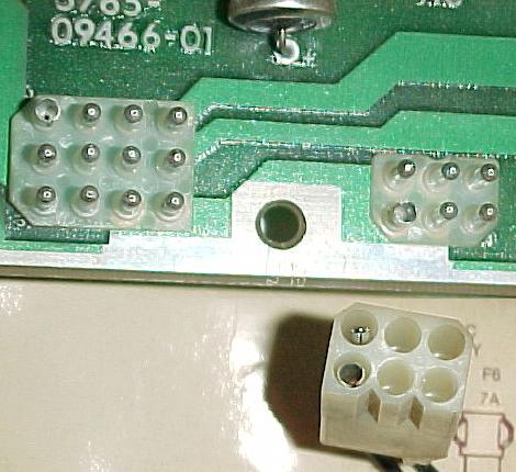
|
The Square Plug Power Supply Connectors 3J1 and 3J2.
Sometimes the two square plug power supply connectors 3J1 and 3J2 get damaged also.
These connectors were used on Williams power supplies system3 to system7
(and also system 11b and DataEast/Sega power supply until 1995). The six pin 3J2 is a ground
connector, and usually does not get damaged. But the twelve pin 3J1 handles
all the input voltages from the transformer to the power supply, so sometimes
it gets burned. Finding the part numbers for these connectors was difficult,
as they were designed in 1971! So
here are the part numbers for these wafer style, mixed pin connectors.
- 12 mixed pin PCB wafer connector, Molex part# 09-18-5121.
- 12 mixed pin wire connector, Molex part# 03-09-1122.
- 6 mixed pin PCB wafer connector, Molex part# 09-18-5061.
- 6 mixed pin wire connector, Molex part# 03-09-1062.
- Male .093" terminal pins for wire connector, Molex part# 16-06-0002.
- Female .093" terminal pins for wire connector, Molex part# 16-06-0001 (new Molex
part# 43080-0001).
Click here for a Molex drawing of these parts.
Removing the Boards from the Backbox.
Before peeling apart the CPU and driver board, make sure to
remove all of the screws securing the boards to the backbox.
Each board is held in by six screws. However, chances are the boards
will not have six screws each, a clear indication that the machine has
been worked on before.
The CPU board sits in a tray, which somewhat locks it into
place. Make sure the CPU board is still in the tray when peeling apart the CPU
and Driver boards. Also notice
when taking the boards apart, how much the driver board flexes during this
operation. The more times the boards are separated, the more chances
that a small break will occur in the connector solder joints.
Installing the Boards.
Once the boards are apart and the inter-board connectors pins replaced,
reconnect the board together again. Make sure that the CPU
board is properly seated in its tray, then from left to right start
pushing the driver board back over the CPU board's male pins. Don't force the board;
if it doesn't go on properly and easily, start over.
Once the boards are back together, reattach the boards to the backbox
with at least two screws each. Then reconnect all of
the header connectors on both boards.
2g. Before Turning the Game On: Circuit Board Sockets
(Dead Game or Random Lockups & Resets)
Most pre-System7 CPU and driver boards used inferior brands of sockets, made by the
Scanbe company, among others.
These sockets are the "closed frame" variety (the printed circuit
board can not be seen under the socket). The problem with these sockets is they
grab the chip's legs on the "thin" side. With
time (these games are 20+ years old!), these inferior socket are not making good contact
with their chips. This can cause random game lock ups, locked on coils
and burnt driver transistors and a blown solenoid PIA, or even cause the game
to not turn on at all!
Left: A "closed frame" SCANBE socket on a System6 game (Firepower).
All closed frame sockets must be replaced with good quality open frame
or machine pin sockets. Note the "SCANBE" name in the blue circle.
Right: An open frame "RN" socket on a different system6 CPU board.
These are much better than their Scanbe brothers, but at 20+ years old,
they can still be problematic.
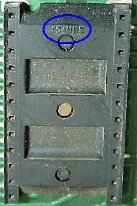
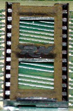
|
The solution to this problem is simple: replace *all* the original
closed frame ("Scanbe") sockets! The "RN" style sockets are better,
but even these can be worn out. Remember these pinballs are 20+ years
old, and chip socket technology has really improved since the late 1970s.
The CPU board has the bulk of the
sockets: One 40 pin socket for the CPU chip, and usually three to seven
24 pin sockets for the game's EPROM and RAM chips. Most of the
time the driver board has no factory installed sockets (but if there are any,
be sure to replace them!)
There really is NO EXCEPTION to this rule. Even if the CPU board in question
does not have Scanbe sockets, chances are good they are dead. There are
only so many insertion/removals a socket will take before it is worn out.
And on these Williams system3 to system7 games, worn out sockets can
cause serious problems, locking on coils and ruining other circuit board
components in the process.
The sound (and speech board,
if the game has one) will also have sockets, for the EPROMs (24 pin) and
CPU (40 pin) chips. Again, if these are the
closed frame (Scanbe) variety, they will need to be replaced too.
Though the sound board sockets are not as critical as the
CPU board sockets, it's still a good idea to replace them.
Do I really Have to Replace All those Sockets?
If the sockets are the closed frame "Scanbe" sockets, yes!
(Some boards used "RN" sockets, and these are generally Ok sockets.)
But as one might guess, it is a big job, and if not careful,
the circuit board can be damaged in the process. But if they
are Scanbe sockets, there really is no choice. Also remember these
sockets are 20+ years old, and probably had an expected life
span of about five years! So just about any socket from this
era can be problematic.
"I Re-Seated the Chips, and My Game Now Works..."
If re-seating a chip or connector causes a game to "work", this
is a BIG RED FLAG that there's a problem. Re-seating is NOT a fix.
It just identifies a problem. The only way to fix the problem
is to replace the questionable socket or connector. If after
re-seating a chip or connector it works, this means the gas tight
seal provided by the socket or connector is gone. And the only way
to fix this is to replace it.
First removal step: pry up the plastic body of the socket to reveal the
socket's pins. Note the condition of the pins. For example, the pins in
the upper right (blue circle) broke as the plastic frame was removed.
This indicates a failed socket. Good thing it's getting replaced!
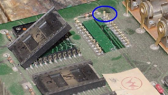
|
Removing the Original Sockets.
Check out pinrepair.com/begin
for the recommended soldering and desoldering tools and techniques.
But for most of these old sockets, the plastic frame on the component
side of the circuit board can be pried up with a small screw driver.
After getting the black plastic frame up, the sockets legs should
be exposed on the circuit board (be sure to check that the screw driver
did not damage/cut any circuit board traces).
After the socket's plastic frame is removed, solder was added to each
socket leg. Then each pin is heated, and pulled out with some small pliers.
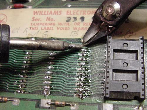
|
With the socket pins exposed, add a small amount of solder to
each leg (this will help distribute the heat when the pins
are removed). Now each leg can be heated with a temperature
controlled soldering iron, and pulled out of the hole with
a pair of needle nose pliers.
After the circuit board's solder hole is clear of the old
socket leg, a Soldapult solder-sucker can
be used to clear the the solder from the circuit board
hole. Sometimes removing the socket's leg with pliers can
be skipped, using the Soldapult to remove both the old
solder and the old socket leg (do this from the component side
of the board).
After all the socket legs are removed, and the circuit board
holes are clear, sand the area with some 220 grit sand paper.
Now carefully examine the area. Are any traces lifted or broken?
Use a DMM set to continuity and double check. Remember nearly all the
personality ROM chips legs "daisy chain" together, so testing
is easy between ROM sockets with the DMM's continuity feature.
Here are the two styles of replacement sockets. The SIP style of machine pin
sockets are ideal. They also allow full access to the circuit board on the
component side, in case of a bad trace. They also allow the socket to be soldered
easily on the component side of the board, if needed. The cheaper plastic socket
behind the SIPs also work, but be sure to mount them up a bit, as seen here.
This way if a plated through hole cracks, the socket can be soldered on the
component side of the circuit board too (though a bit tricky, it can be done).
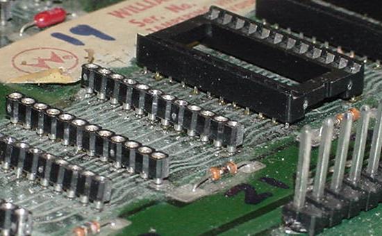
|
Use Good Quality Sockets.
Always install a new socket! Don't solder chips directly
into the circuit board.
The best socket to use are SIP (Single Inline Package) machine pin sockets.
These allow access to all the traces around the new socket.
The sockets can even be soldered from the top side of the
board, if needed. But conventially open frame mid-priced sockets
also work well (AMP is a good socket brand). Just make sure
the new sockets grip the chips leg on *two* sides (not just one!)
Socket Installation Tip.
If using standard tin open frame sockets and
not SIP or machine pin sockets, it is always a good idea
to mount the socket up above the circuit board just a bit. Obviously
the socket legs must go through the board to the solder side, but
the higher the chip socket above the circuit board the better.
This allow the soldering of the socket from the *top* of the circuit
board if the need arises. For example, if the plated through hole
cracked when removing the old socket or chip, being able to solder
the new socket from both sides of the circuit board is ideal
(this is why machine pin sockets are better than inexpensive tin sockets).
Solder Flux Removal.
All electronic 60/40 solder has rosin flux inside the solder.
This helps clean the solder joint, as the solder is applied,
and helps the solder stick. But after removing all the old
sockets and installing new ones, this flux should be removed.
This should be done because metal particles can get stuck
in the flux, and short out adjacent contacts.
The easiest way to remove the solder flux is to use an old toothbrush and
some 90% (or better) Isopropyl alcohol. Just put the alcohol on the
board and use the toothbrush to scrub the flux off. It only takes
a minute, and the alcohol dries quickly leaving a nice clean board.
* Return to the Pin Fix-It Index
* Go to Part Two System3-7 Repair Guide
* Go to Part Three System3-7 Repair Guide
|

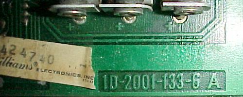
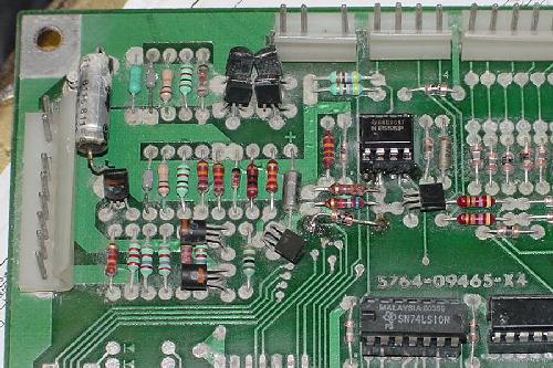
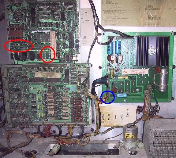
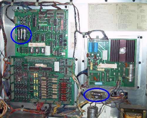
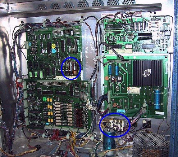
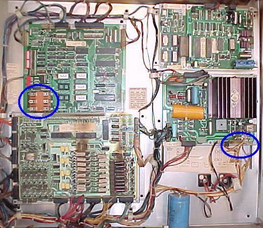
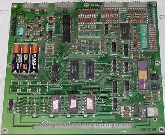
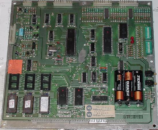
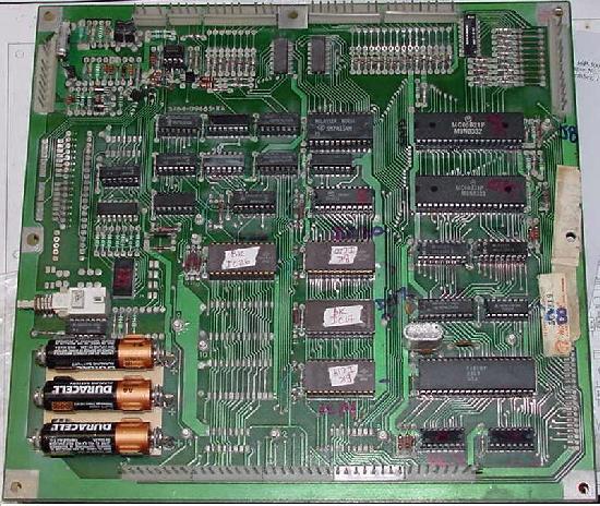
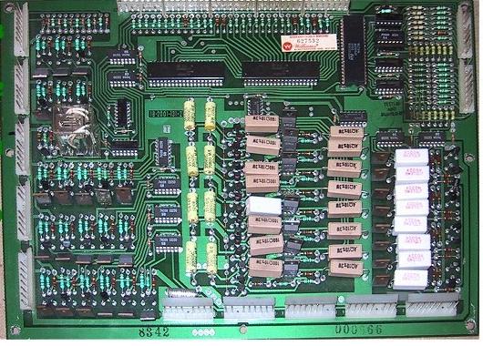
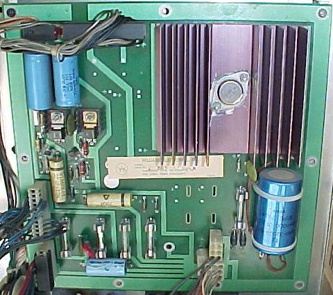
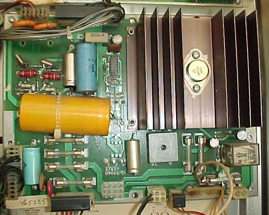
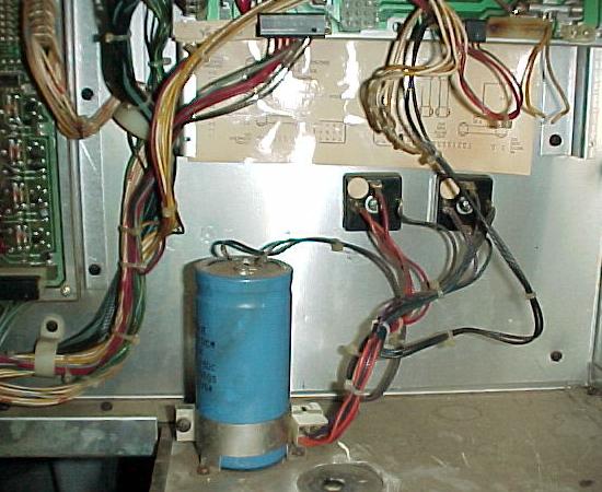
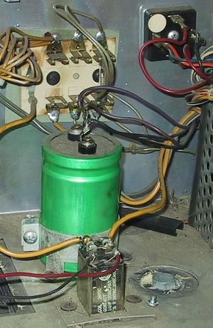
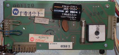
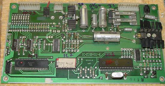
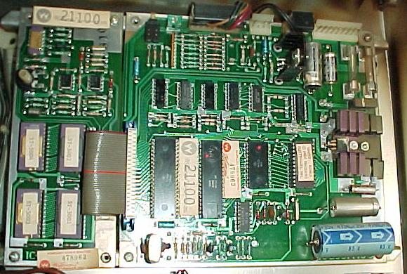