cfh@provide.net
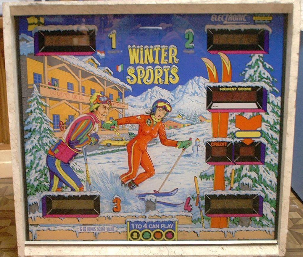
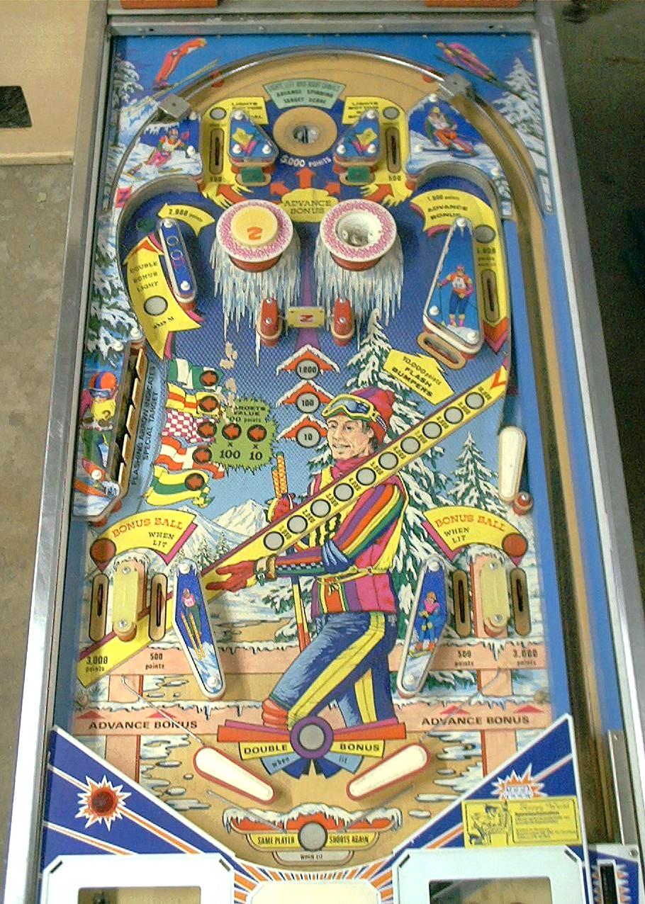
- 01/1978 Winter Sports. Sound generated by the driver board.
CPU board uses five 2708 EPROMs.
BG, PF, boards. CPU board uses five 2708 EPROMs.
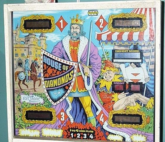
- 07/1978 House of Diamonds.
Sound generated by the driver board.
CPU board uses five 2708 EPROMs.
BG, PF, boards.
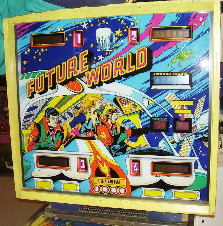
- 10/1978 Future World.
Sound generated by the driver board.
CPU board uses five 2708 EPROMs.
BG, PF, game.
- 04/1979 Shooting the Rapids.
First game with a dedicated sound board.
CPU board uses five 2708 EPROMs.
- 09/1979 Hot Wheels.
CPU board uses four 2708 EPROMs and one 2716 EPROM at IC1.
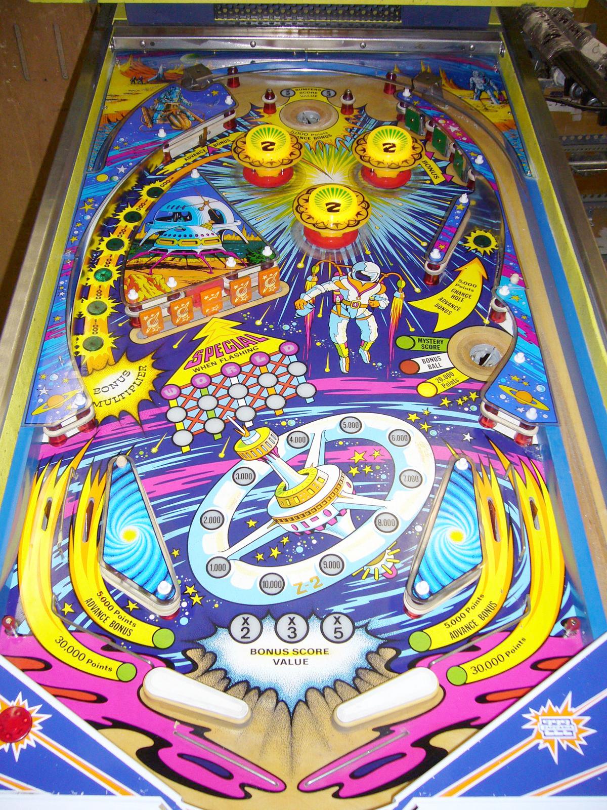
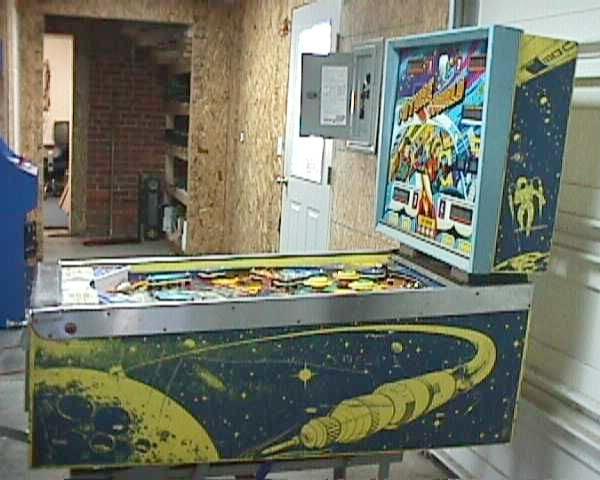
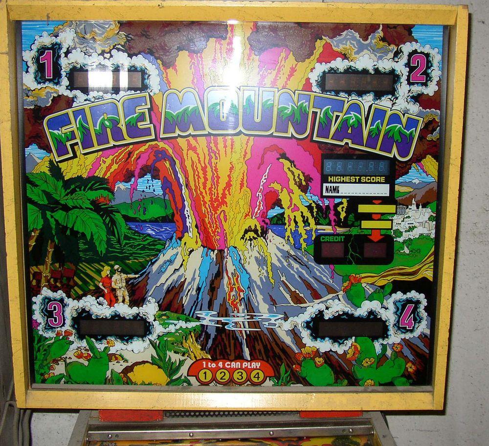
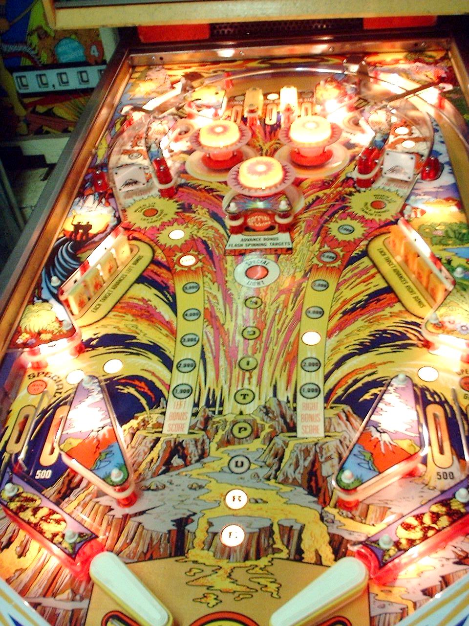
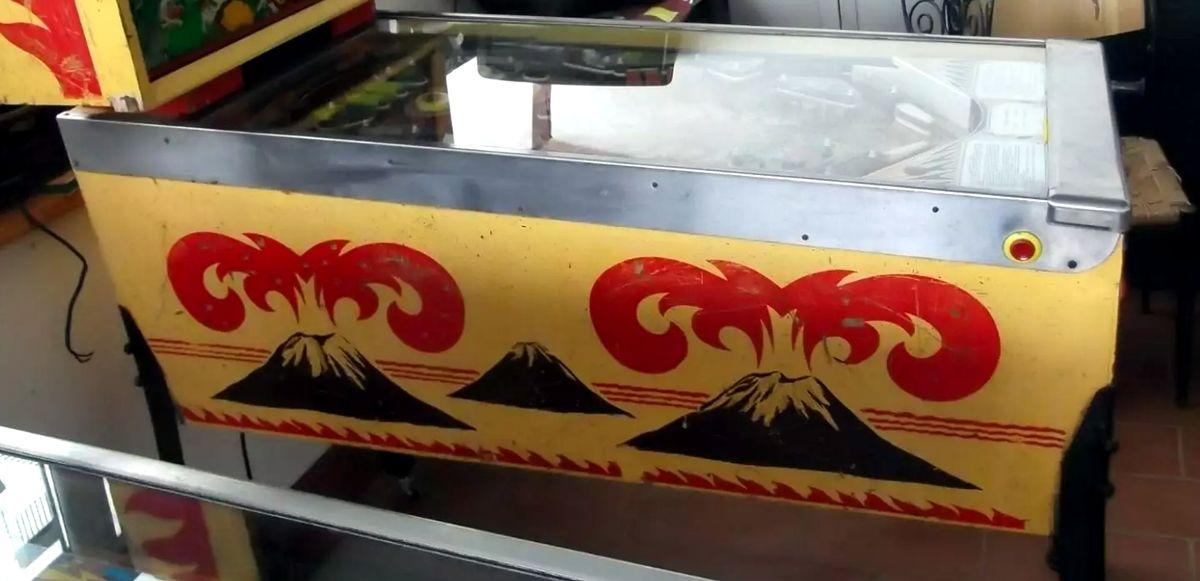
- 01/1980 Fire Mountain.
CPU board uses four 2708 EPROMs and one 2716 EPROM at IC1.
BG, PF, cab.
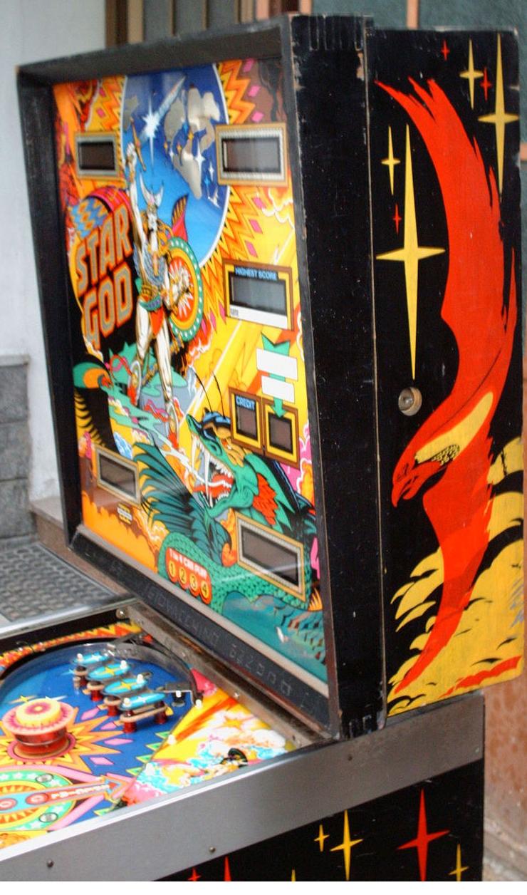
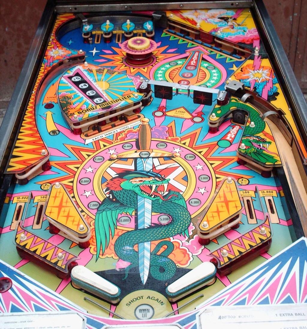
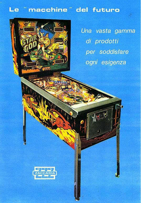
- 05/1980 Star God.
CPU board uses four 2708 EPROMs and one 2716 EPROM at IC1.
BG, PF, Flyer.
- 09/1980 Space Shuttle.
CPU board uses four 2708 EPROMs and one 2716 EPROM at IC1.
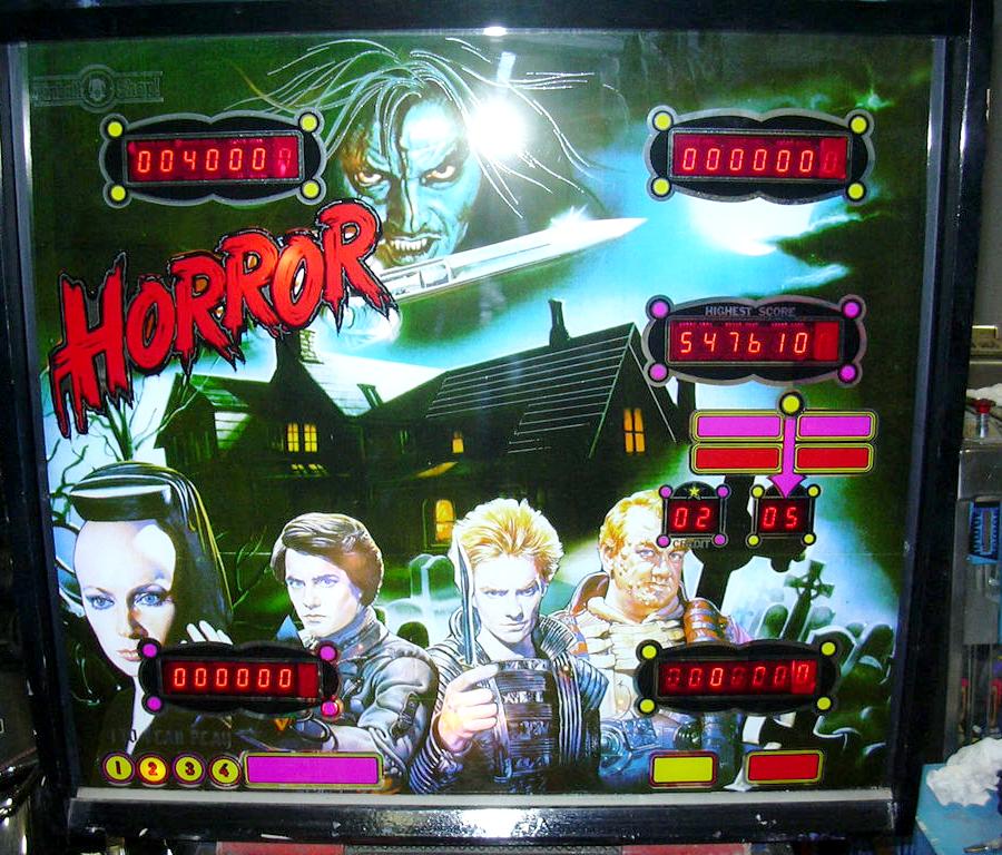
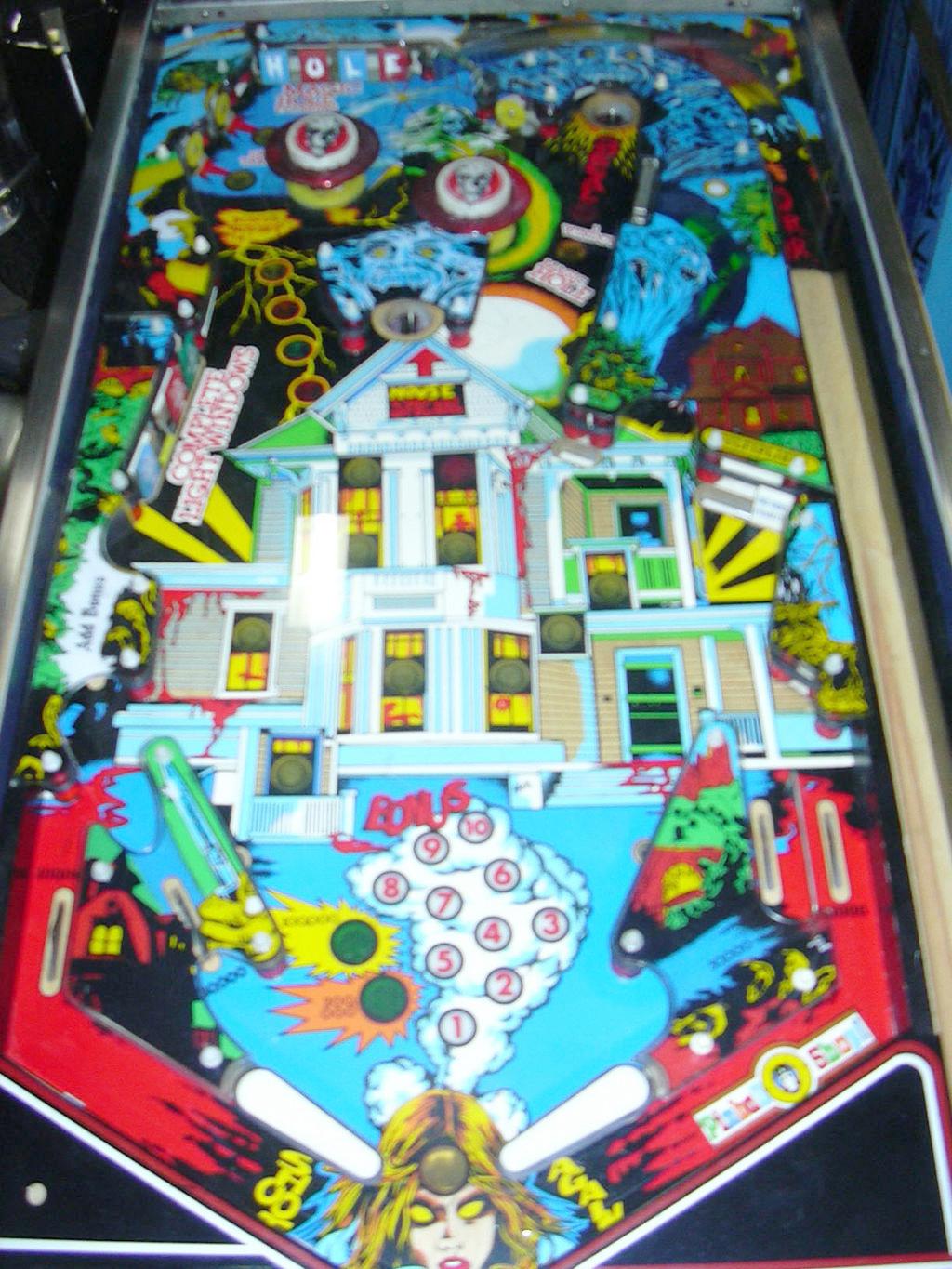
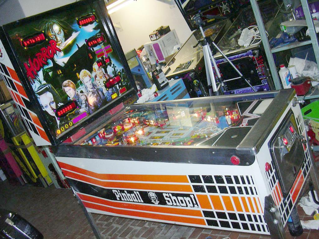
- 09/1980 Horror.
A Space Shuttle conversion kit. Uses different game EPROMs.
BG, PF, game.
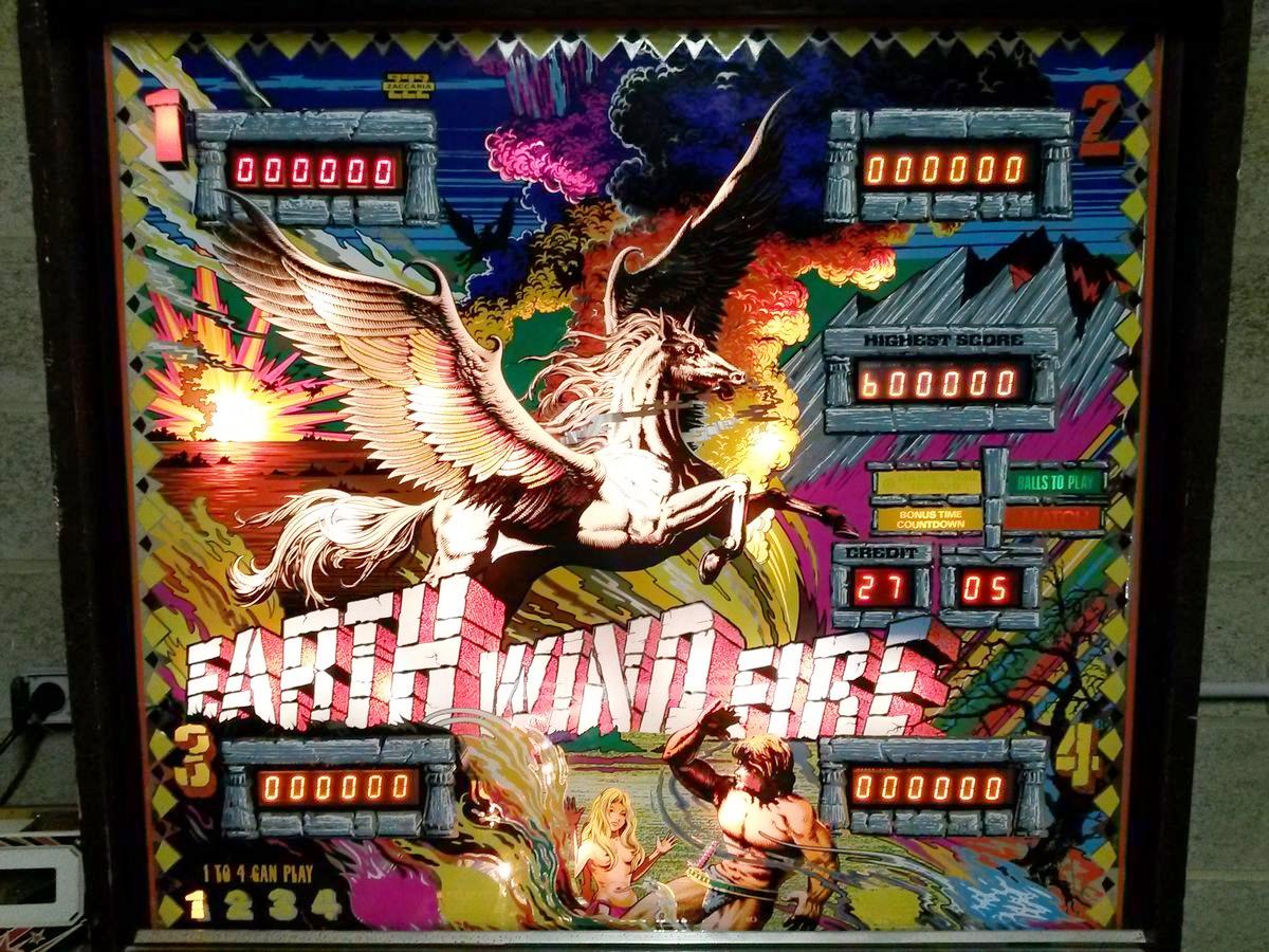
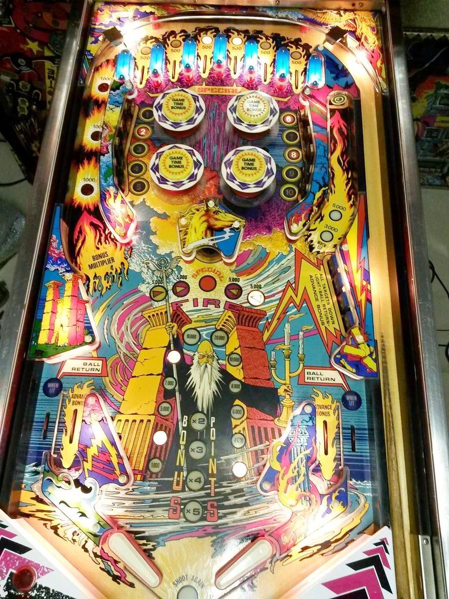
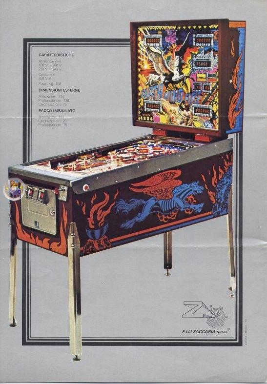
- 04/1981 Earth Wind Fire.
CPU board uses four 2708 EPROMs and one 2716 EPROM at IC1.
BG, PF, Flyer.
- 09/1981 Locomotion.
The most advance Gen1 Zac game.
CPU board uses three 2708 EPROMs and two 2716 EPROM at IC1/IC3.
Generation2 solid state Zaccaria
Gen2 Zaccaria games are the ones more people seem interested. They
have many good features and are quite fun. Most have speech with
the sound, and all these games have attract mode cpu controlled lighting (unlike Gen1 games.)
- 04/1982 Pinball Champ '82, 7 digit score displays.
- 09/1982 Soccer Kings, 8 digit score displays.
- 04/1983 Pinball Champ, 8 digit score displays.
- 04/1983 Time Machine, 7 digit score displays
- 09/1983 Farfalla, 7 digit score displays.
- 04/1984 Devil Rider, 7 digit score displays.
- 09/1984 Magic Castle, 8 digit score displays.
- 01/1985 Robot, 8 digit score displays.
- 07/1985 Clown, 8 digit score displays.
- 12/1985 Pool Champion, 8 digit score displays.
- 03/1986 Blackbelt, 8 digit score displays.
- 07/1986 Mexico 86, 8 digit score displays.
- 12/1986 Zankor, 8 digit score displays.
- 1987 Thunderman (Appletime), 8 digit LED score displays.
- 1987 X Force (Tecnoplay)
- 03/1987 Scramble (Tecnoplay), 7 digit score displays.
- 04/1987 Spooky, 8 digit score displays.
- 07/1987 Star's Phoenix, 8 digit score displays.
- 08/1987 New Star's Phoenix
- 1988 Spaceteam (Tecnoplay)
- 1988 Fast Track (Mr.Game)
Note Mystic Star is not included in this list. Mystic Star is a Bally -35
conversion game, and uses Bally boards. Hence it is not covered in this document.
1e. Circuit Board general description.
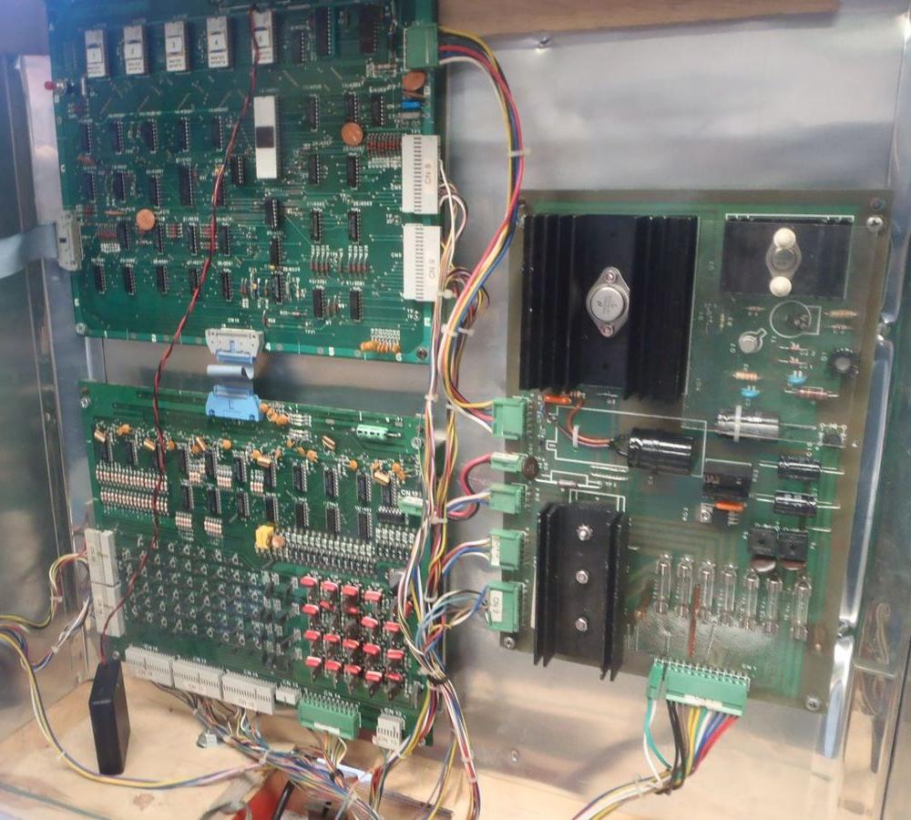
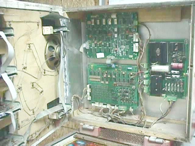
Essentialy there are three or four boards in any Zaccaria pinball
game: power supply, CPU board, driver board (or "interface" board
as Zaccaria calls it), and sound board (on games Shooting the Rapids
4/79 and later.) There's also a transformer in the bottom of the
game, which provides raw AC voltages to the power supply (when
then converts them to DC voltage, and regulates some of the voltages.)
You will hear a lot in this document discussions of "generation1" and
"generation2" games and/or boards. What this refers to is the
progressive change in the Zaccaria pinball boards, as time marched on. The
biggest change in the two systems was ROM space (or lack of
it on gen1 CPU boards.) Gen1, at it's end (Locomotion), could
support three 2716 EPROMs and two 2708 EPROMs. That's about
7000 bytes of programming space (not much frankly.) With
the gen2 CPU board, this changed to two 2764 EPROMs for a
total of 16000 bytes (more than double the gen1 CPU board.)
This allowed more programming and more features, that went
along with greater programming.
In addition, all gen1 games used 6 digit score displays.
With gen2, they moved to 7 digit and 8 digit displays.
Also the sound boards really evolved to have
some pretty awesome digital sound. On gen1 games the
most involved sound was on Locomotion, which was a
clone of Williams Firepower style sound (with no speech
and no background sound.) With Gen2 games, the sound
boards became a lot more sophisticated, with most
games have some pretty involved speech (with ROMs
available in multiple languages like Italian, French,
German and English.)
Power Supply Board.
Gen1 and Gen2 power supplies are different. Mostly the connectors
are different. Then essentially supply the same voltages. But you
can't interchange the two power supplies because the style of connectors
is different.
In the upper right section of the power supply is the high voltage
for the score displays. In the lower right section are the input
fuses. Usually the fuse holders are junk on these, and should
be replaced. As a rule I replace all of them. New fuse holders
(in the style of Dataeast) have a slightly different foootprint,
and you end up drilling a new hole to make them fit (see the
power supply section of this document for more info on that.)
The power supply CN1 connector (lower right) is problematic.
This is the raw transformer voltage plug that inputs power
to the power supply board.
On CN1 the four pins on the left of this connector, Green and White
wires, which bring the raw voltage from the transformer for the
CPU controlled lights, really likes to burn. For this reason you
will often see this connector replaced, or wires soldered directly
to the back of the board. Note there are no General Illumination
fuses on the power supply board.
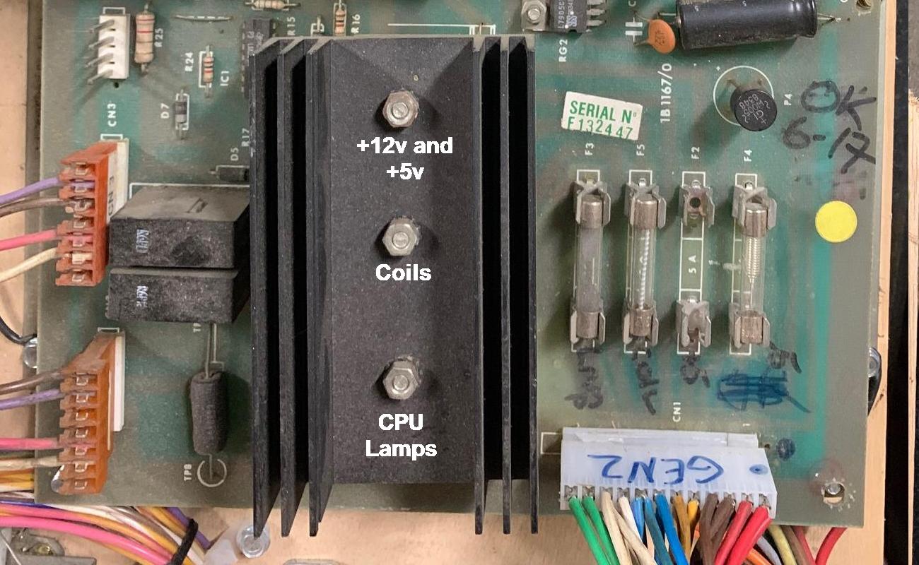
Gen2 Zaccaria power supply.
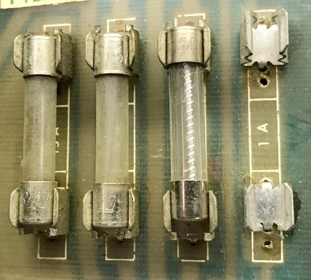
The power supply fuses are designated as such, and ordered left to right:
- F3: Lamp power cpu controlled
- F5: Coils
- F2: +5 volts (game logic)
- F4: -5 volts (sound)
- F1: high voltage (top middle of board)
CPU Board.
As stated above, the Gen1 CPU board has limited ROM space.
There's sockets for five EPROMs. Small EPROMs at that, 2708
sized (1k bytes), with the ability of three of them to be
jumpered to 2716 EPROMs (2k bytes.) Locomotion, the last
Gen1 game, used the most EPROM space, and needed a jumper
mod to utilize three 2716 EPROMs.
Gen1 CPU board for Zaccaria Space Shuttle.
Locotion factory jumper mod for a 2716 EPROM from U11 pin6
to the top of jumper pad J2. Also the trace on the componenet
side going to U11 pin6 is cut.
Driver Board.
The gen1 and gen2 driver boards are very similar. The main difference
being connectors (.100" old and new styles), and the number
of coil driving transistors (21 on Gen1, Q1-Q21, and 24 on Gen2.) They
both used SCR (2n5060 and a few T106) lamp drivers for a total of 64 lamps
on Gen1 (SCR1-SCR64), and 80 lamps on Gen2.
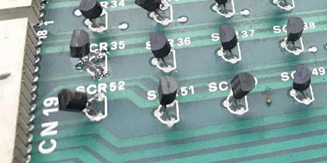
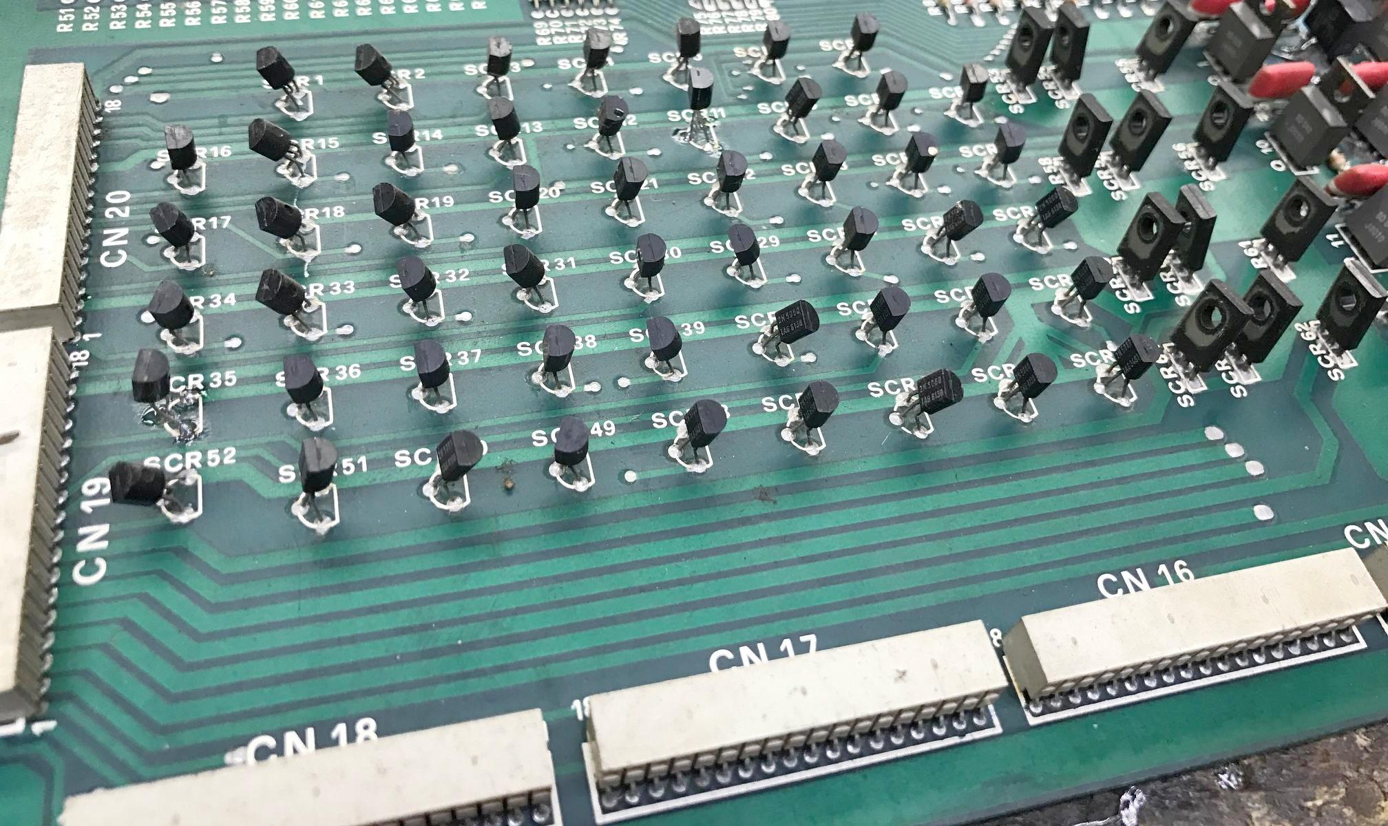
Gen1 driver board. Note the .100" old style connectors and
the green .156" connector.
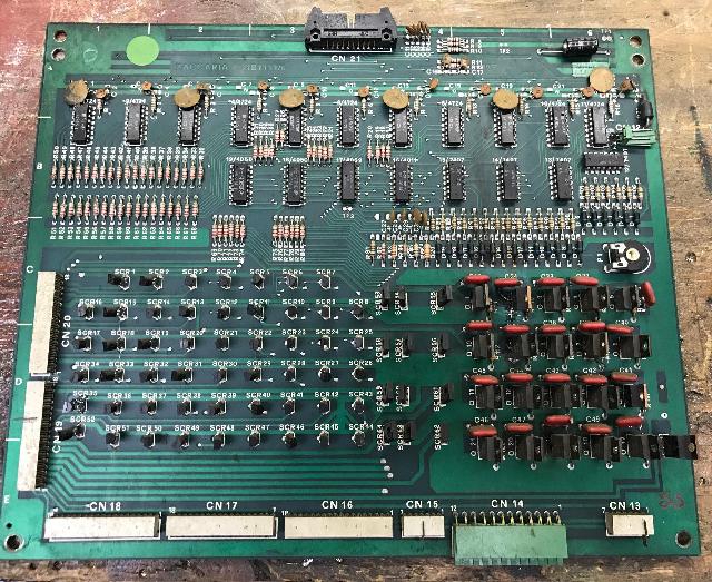
Gen1 driver board. Notice the screening for the lamp drivers (2n5060)
is done incorrectly compared to how the SCRs are actually installed. Oops!
1f. Connectors.
Gen1 Connectors.
Generation1 games have the "weird" connectors. They are a problem,
as simply put, they just are not available. The .100" connectors (switch matrix
on the CPU board and lamp matrix on the Driver board) are quite strange.
The removalable part, which typically is the female section, are reversed.
That is, the removeable part is the male portion! These are long discontinued
and if missing/molested, you're frankly screwed. The only solution is to
replace both the male and female portions with standard .100" substitutes.
MPU board .100" connectors. Notice the non-standard reverse
pin orientation, where the male section is the removeable part.
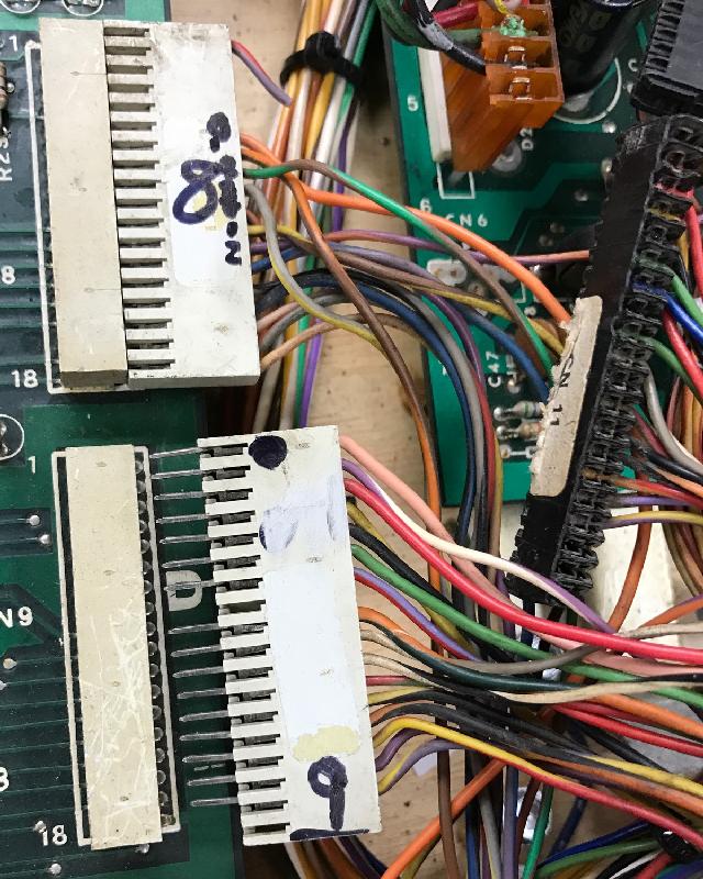
Power supply Gen1 connectors, top .100 and bottom .156".
Gen2 Connectors.
With Gen2 games the .156 connectors got more "normal" and standard,
using IDC style connectors. These can be repaired with standard
Trifurcon connector pins and housings.
Power supply Gen2 connectors .156" style. Notice the use
of flipper relays on the power supply.
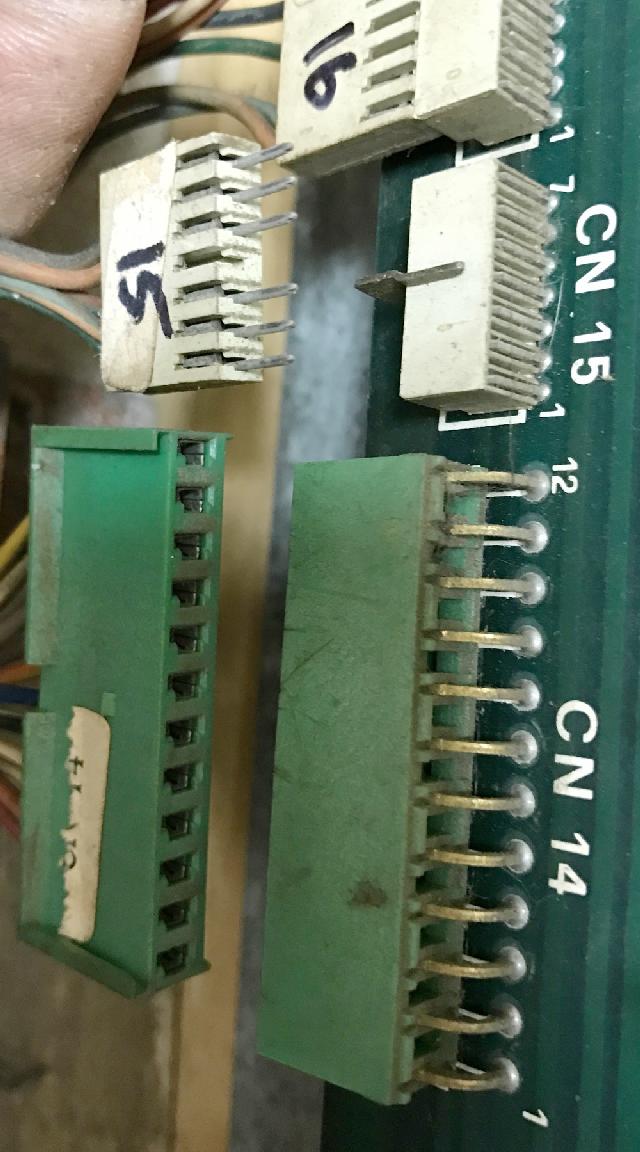
The green Gen1 .156" connectors (as used say at the MPU board at CN7)
are pretty impossible to find. Fortunately there is an answer. You can
use standard .156" Molex style connectors. On the female side, it's
really easy - the new female Molex .156 standard housing fits right
over the Zaccaria Gen1 male pins. Just make sure you use Trifurcon
Molex .156 pins!
MPU supply Gen1 connectors .156" style. This was replaced
with a standard Molex female .156 connector housing with
trifurcon pins. This works well since the original female
(or male!) connectors are not available.
On the male side, the original green right angled .156 Zaccaria
Gen1 connector pins can be replaced with Molex .156 male pins.
But this replacement is not easy. I don't suggest doing this
unless there's no choice... The Molex pins are more square
than the original rectangle Zac .156 pins. So they don't fit into the
original board holes unless forced into place. It's not the
worst thing in the world... it does work... but if possible
avoid replacing the male Zac .156 pins with Moles male pins,
unless absolutely needed.
2a. Before Power On: Coil Resistance
Will report back with Zaccaria coil resistances here...
2b. Before Power On: Removing the battery and fixing corrosion
Add info on using a CR2032 lithium coin battery on the Zaccaria MPU board...
3a. Repair: Power Supply
Transformer Assembly.
Before we dive into the Zac power supply, we should discuss the
transformer assembly first. Gen1 transformers are pretty simply
and exposed, much like say an EM or early Bally/Stern games. But
with Gen2 Zaccaria games, the transformer assembly became much more
complicated and enclosed. A metal transformer frame goes around the
huge transformer, sheilding itself from eyes (and hands.)
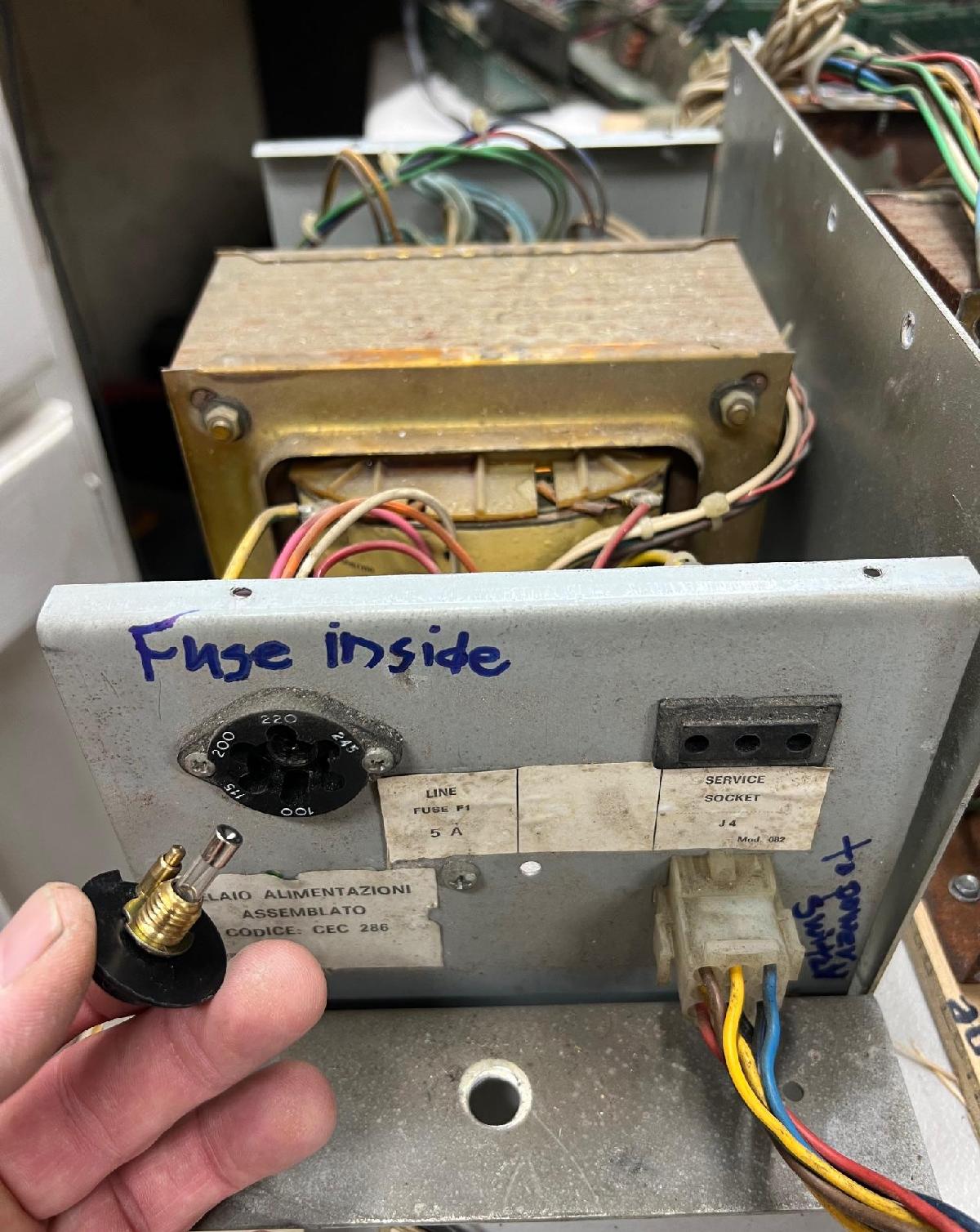
But the big change with Gen2 transformers is the ease of
input line voltage change. If you want the game to run at 115 volts
instead of 220 volts, there's a plug on the front of the transformer
assembly that allows this is just a few seconds. Unscrew the plug,
turn it to 115 volts (or whatever you need), re-insert and screw
back in place. No tools needed.
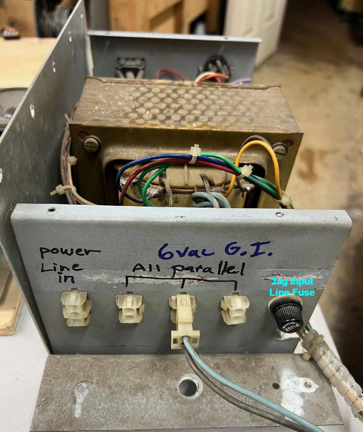
Now be aware that the voltage selection plug also have a GMA 20mm European
fuse inside. Actually there's two fuses on the transformer assembly...
There's an American style 3ag (1.25") screw-in fuse on the back side of
the transformer assembly. And of course the
mentioned GMA 20mm European fuse on the input voltage selection plug. Obviously
if either fuse is blown, the game will be "dead". So keep that in mind.
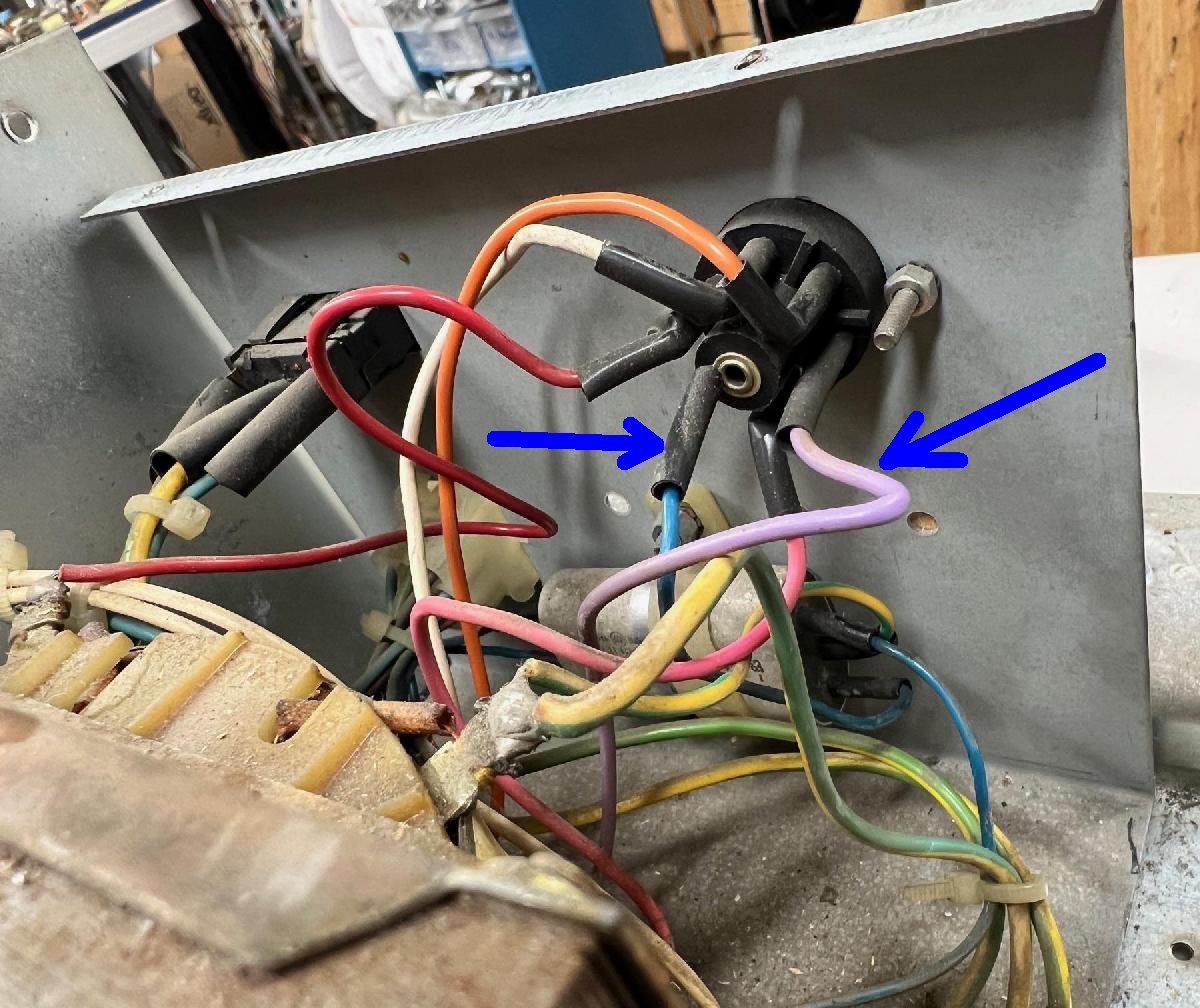
Additionally sometimes the voltage plug goes missing. This is a major
bummer, as it makes the game completely dead. Unfortunately finding a
replacement plug is near impossible. But there is a way around this.
Take the top metal cover off the transformer assembly
and look at the voltage selection plug's female side,
you can adapt a 3AG American sized fuse into
the transformer assembly. I've done this before where the voltage selection
plug is missing. In the case of 115 volts, cut the Violet wire at the voltage
plug, and then cut the Blue center wire. Lengthen and route these wires
outside the transformer assembly to a new 3ag fuse holder. Now the game
is set to 115 volts, and the fuse is easily accessible. It's a hack,
but there's not much else you can do if the voltage selection plug is missing.
Back side of a removed Zaccaria Gen2 transformer assembly.
Front side of a removed Zaccaria Gen2 transformer assembly, showing the
voltage selecton plug and it's internal GMA 20mm fuse.
If the voltage selection plug is missing, you can hack in
a standard 3ag fuse holder by cutting the violet and blue center
wire (for 115v), lengthen, and attach to a remote 3ag fuse holder. I drill
a hold through the transformer metal frame housing and mount the new 3ag fuse
holder outside, allowing easy access and visibility to the fuse.
Power Supply Board.
Gen1 and Gen2 powers supplies are similar, but not compatible.
That is, you have to use a gen1 power supply in a gen1 game.
And likewise, use a gen2 power supply in a gen2 game. It's not
that the designs are so different, but more of the style of
connectors used. They both use a .156" connector, but the gen1
connectors are "different." The gen1 green connectors (with
the "flap") will not work with a standard .156" female housing.
Hence the gen1 power supply won't mate with a gen2 game (which
frankly is probably a good thing.) Also generally speaking,
the connectors (even if the same) are not pinned alike, so
the are not "plug compatible".
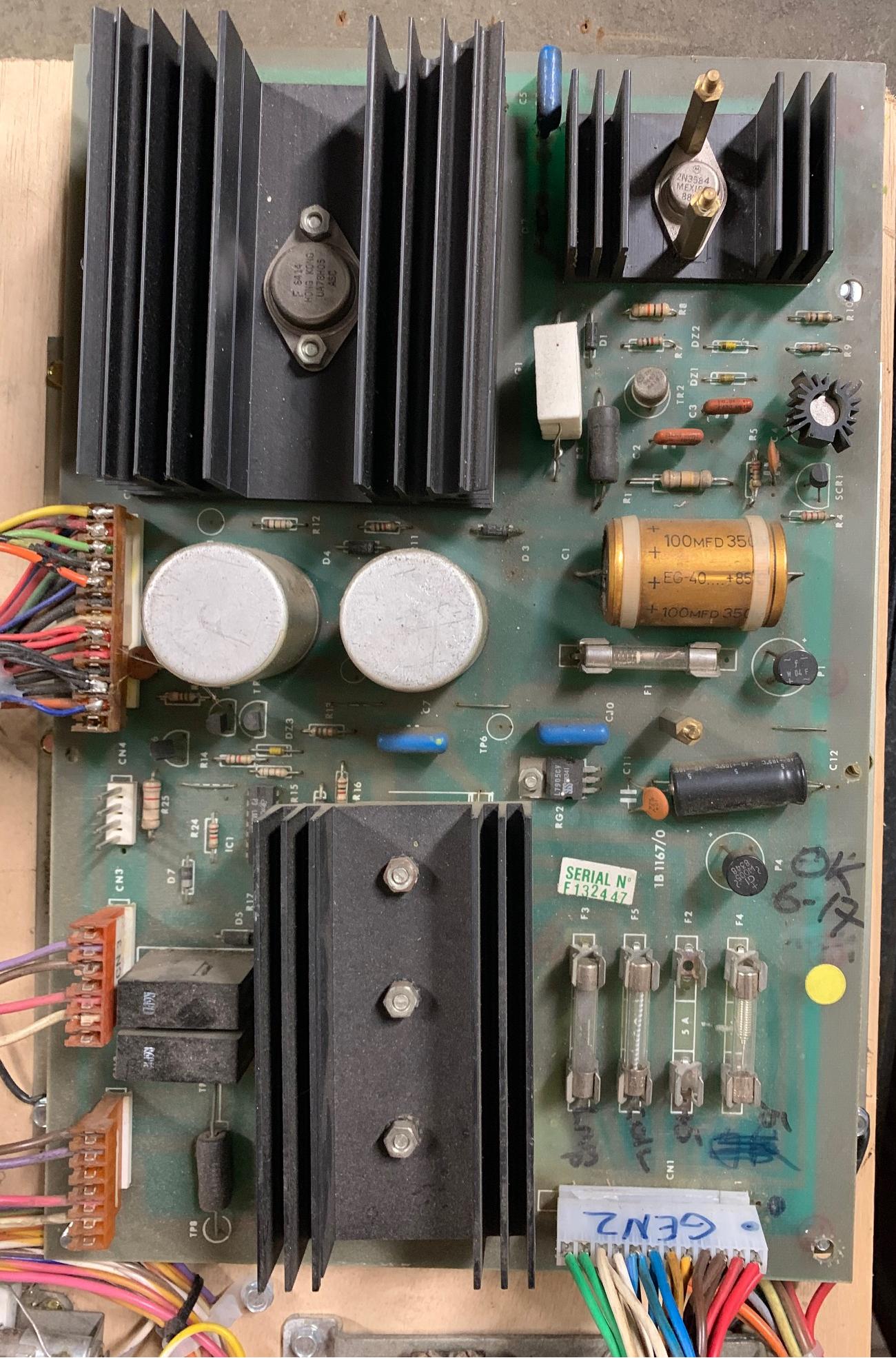
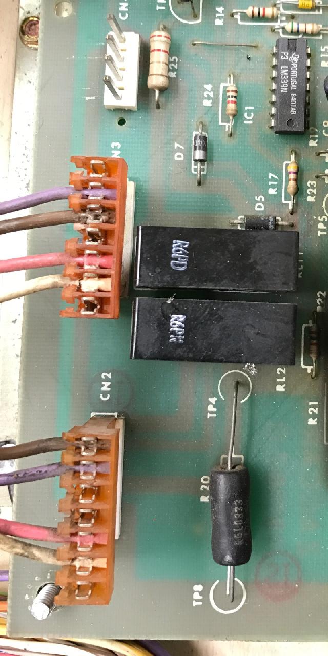
Gen1 power supply with a changed CN1 connector.
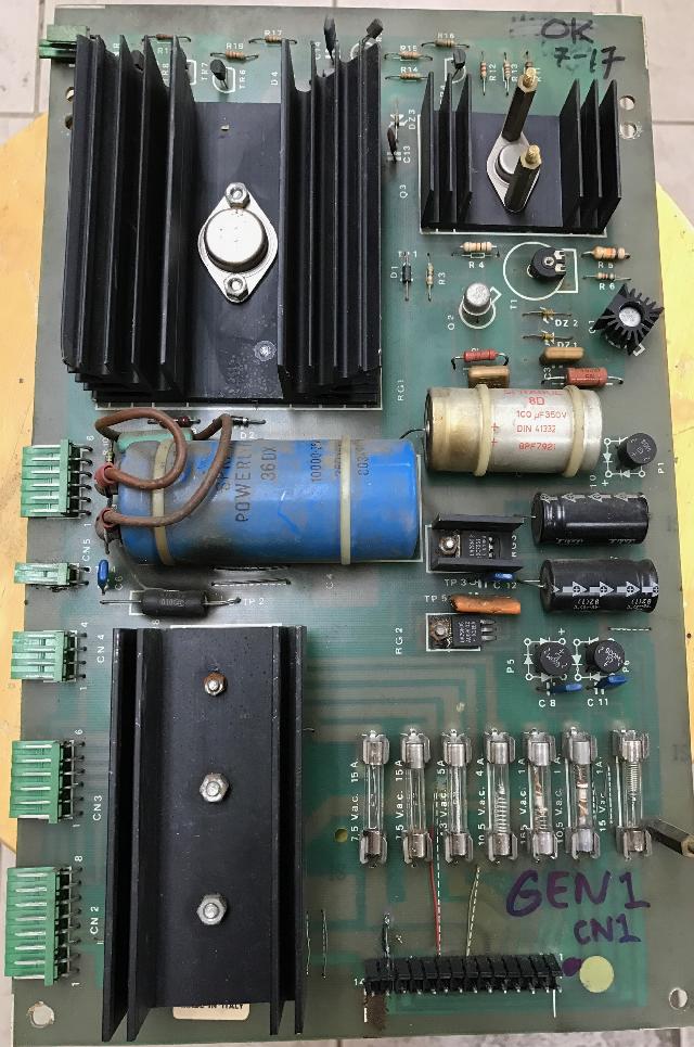
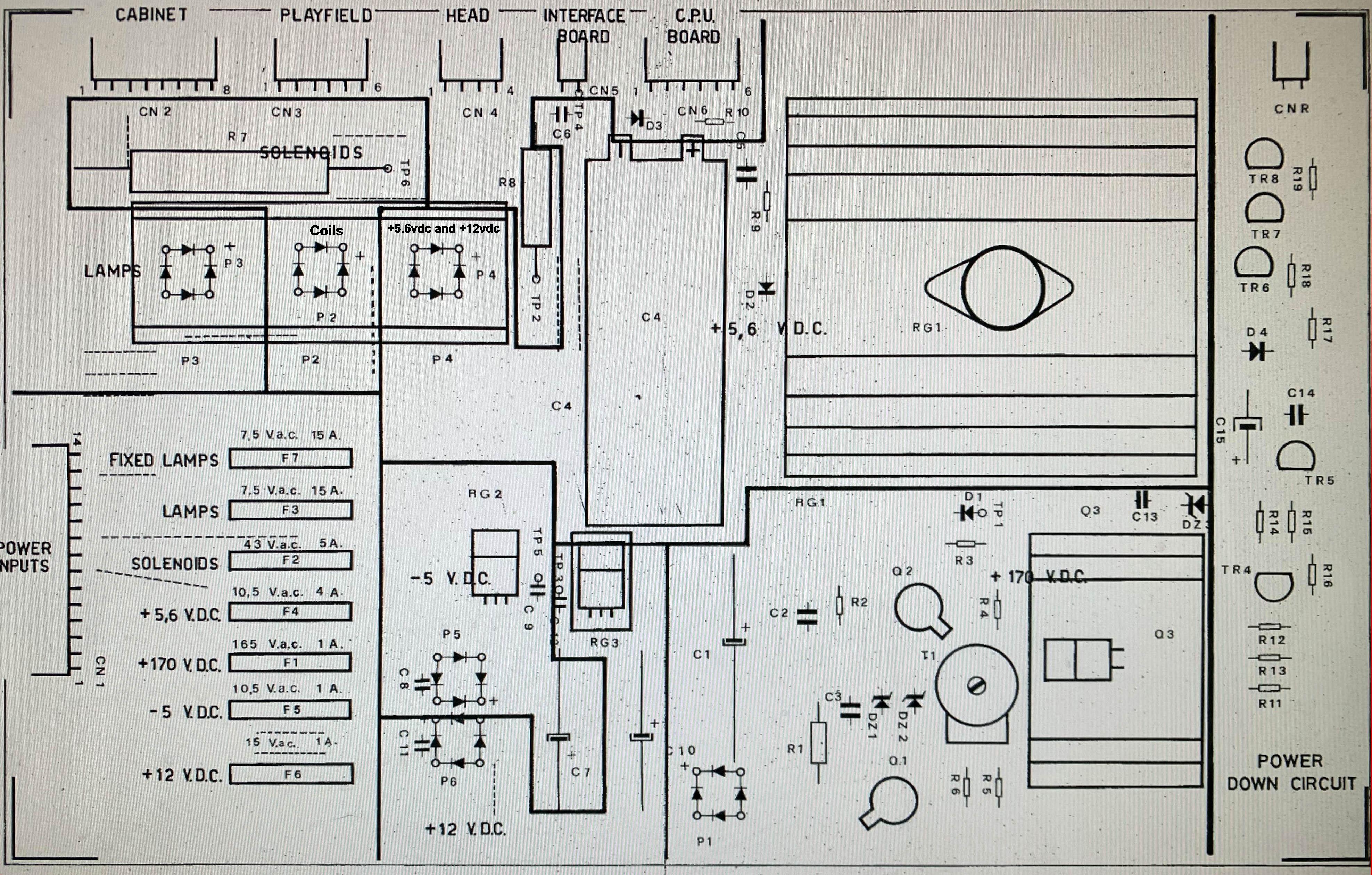
Gen1 power supply layout.
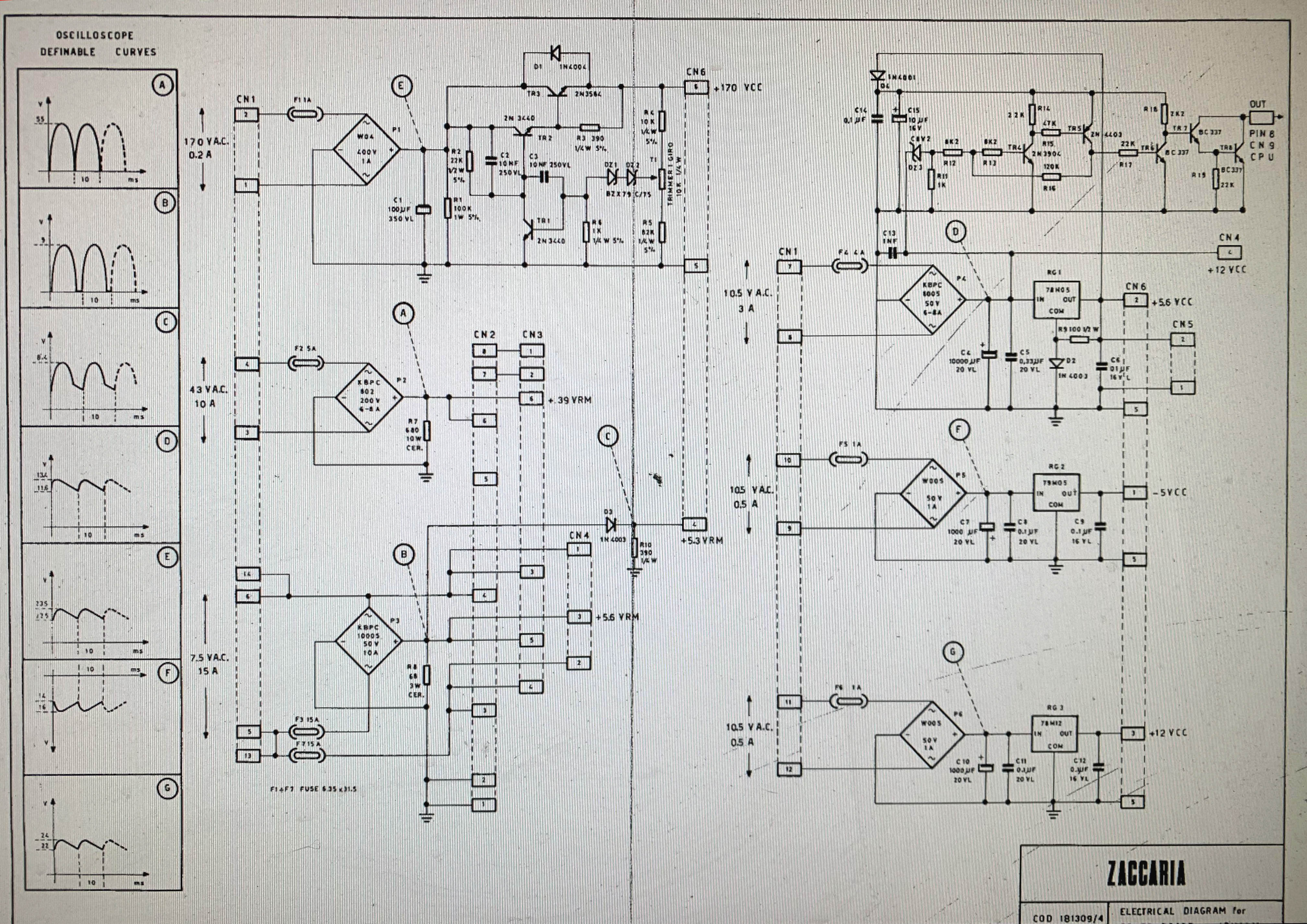
Gen1 power supply schematic.
Gen2 power supply.
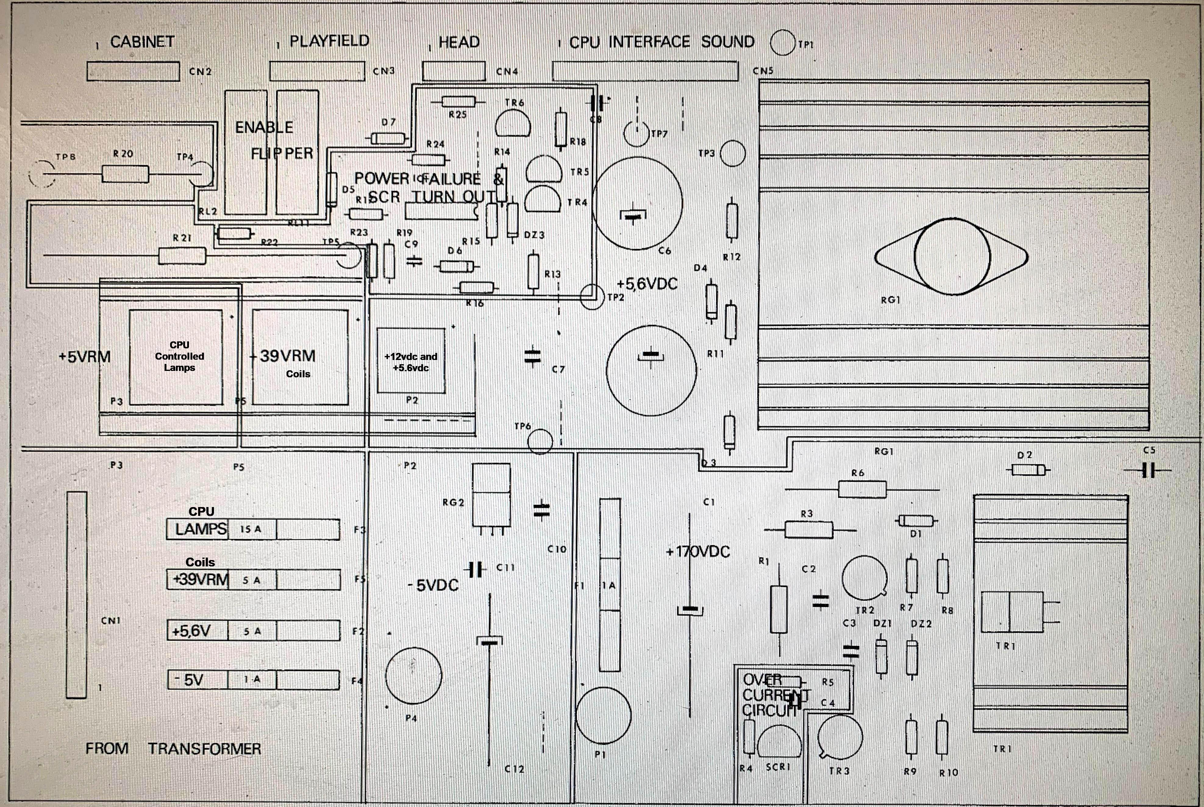
Gen2 power supply layout.
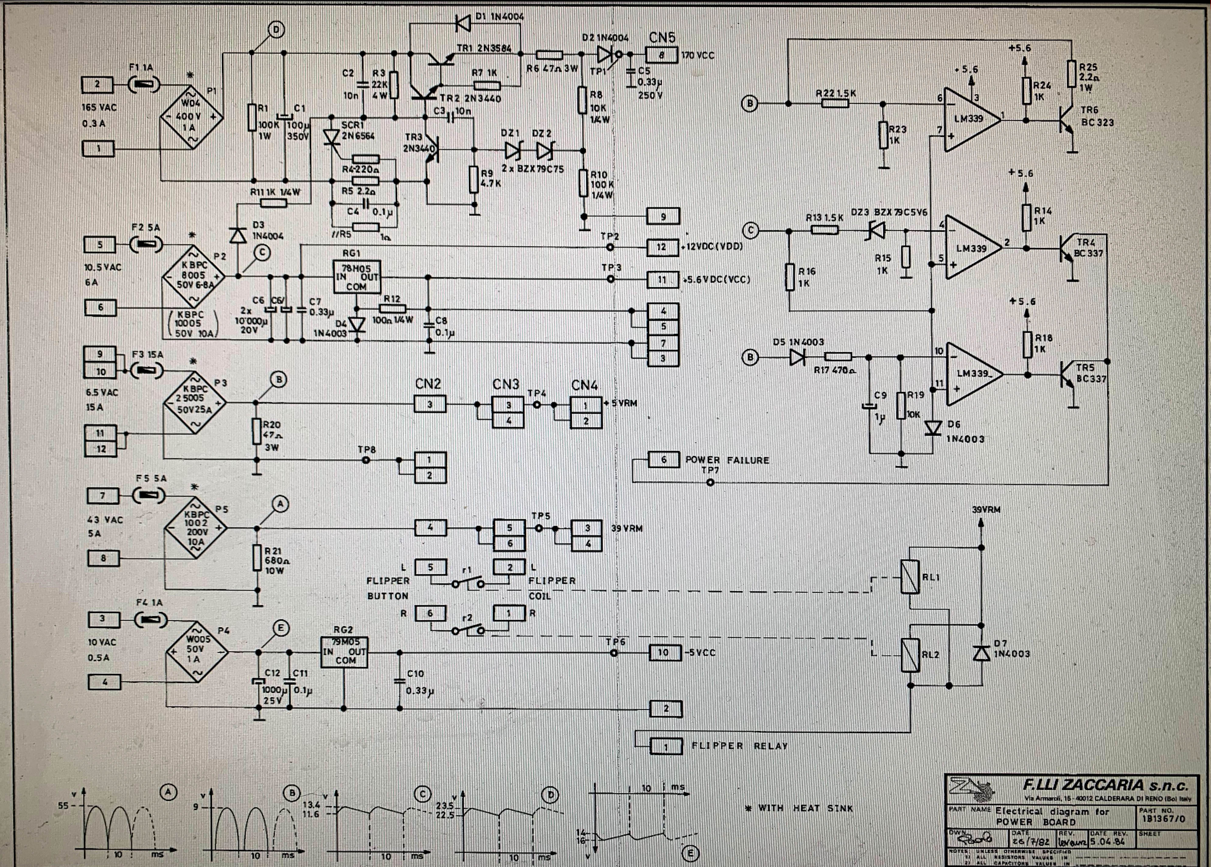
Gen2 power supply schematic.
Other changes from Gen1 to Gen2 include the addition of the flipper
relay on gen2 power supplies. In Gen1 games, the flipper relay
(which turns "on" the flippers when a game is started, completing
the path to ground) is a descrete device, and mounted under the playfield.
Also gen1 power supplies provide -5 volts to the CPU board for
the games that use CPU EPROMs that need -5 volts.
Though gen2 power supplies do create -5 volts, it is *not* directed
to the CPU board (there's no need for it, due to the change to
EPROMs that don't require -5 volts.) Instead the -5 volts on
gen2 games goes to the sound board.
Lastly the GI (general illumination) or "Fixed Lamps" (as Zaccaria calls them)
is handled differently on gen1 and gen2 games. On gen1 games, the GI fuse is mounted on
the power supply. On gen2 games, there is *no* GI fuse on the
power supply (it's mounted in the back box.)
Also gen2 power supplies have a "power fail" circuit. Gen1 power supplies do
not have this.
For the gen1 green .156" connectors, apparently
there is no compatible replacement available today.
This is unfortunate, as the large connector CN1 at the
bottom of the gen1 power supply likes to burn.
These green connectors were made by Amp,
and can't find any sort of compatible replacement.
The only solution is to replace the male green gen1 connector pins
with standard .156" male pins and use a corresponding female .156 connector,
with Trifurcon pins. Note to do this, the holes will have to be drilled
for the male connector pins using a 1/16" drill bit (this is not a big
deal as the power supply board is single sided, so there's no plated through
holes to ruin.)
Top: the .100" style connectors used on Gen1 Zaccaria games.
Bottom: the .156" style green connectors used on Gen1 Zac games.
On gen1 lamp and switch matrix connections, the .100" connectors used
are not available. Again not been able to locate a compatible replacement connector.
Fortunately these connectors are usually in decent condition,
unless butchered by somebody.
Power Supply Fuse Clips.
The fuse clips used on both gen1 and gen2 power supplies are cheap and
corrode easily. It is highly suggested to just replace them all with
new fuse clips. Unfortunately the stock Zac fuse clips are a different
in size to what is readily available today. This isn't a big deal though.
It just requires drilled on new 1/16" mounting hole for each fuse clip
(utilizing one of the two stock holes), and enlarging the other stock
hole with a 1/16" drill bit. Again the power supply is a single sided board,
so drilling out the holes does not compromise the design.
Enlarge one hole on each clip, and add one new hole to fit the new fuse clip.
Mouser sells a decent fuse clip, part number 534-3513 (plated brass). Again all fuse clips
should be replaced.
Gen2 Fuse block. These fuse clips have been replaced with modern 3AG
clips which are available today. Notice the fuse clips on the right,
and the two new holes drilled to accomodate the new 3AG clips. (The
unused two holes were from the original Zac style fuse clips.)
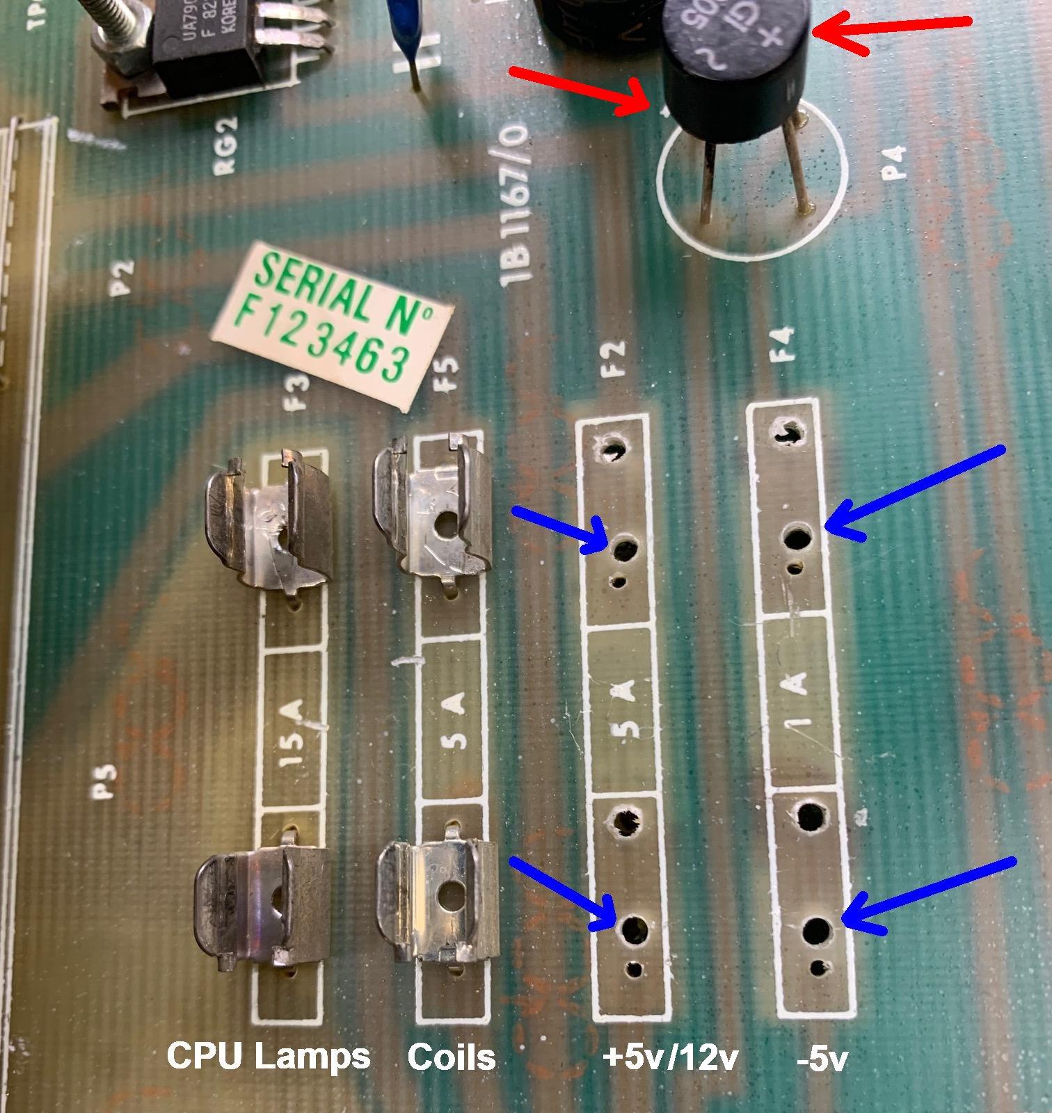
Gen2 Fuse block. Here the larger holes were drilled out so new
modern 3AG fuse clips could be fitted. The blue arrows indicated new
holes for the US sized fuse clips... Also notice P4 bridge
rectifier for the HV section at the top of the picture. Kind of weird
how the "+" on the bridge is directly opposite the "+" on the
board (red arrows.) That's how it is with this bridge and for the
small P1 bridge too!
Power Supply Bridge Rectifiers.
There are three large bridge rectifiers mounted under the large heat sink in the on
the power supply board (both gen1 and gen2). They are lug-type bridges but frankly
you can replace them with either lug or wire style. The lug style is a bit
more "sturdy", but wire style 35amp 200volt bridges can also be used are are far easier to install.
On gen2 the small round P1 and P4 bridges are for the high voltage and -5 volt sections, respectively.
This is unlike saw Bally power supplies where the HV is four discrete 1n4004 diodes. Notice
how the "+" on these two bridges is opposite the "+" marked on the board!
In addition, the -5 volt bridge (P4) goes to a 7905 (RG2) to develop
the -5 volts for the sound card.
Below is a picture of what the bridges are used for.
Gen1 and Gen2 bridges.
Below is a table of the bridges used. Note these can all be replaced with
25 amp 200 volt (or higher) wire or lug style bridges, mouser part number 583-MP254.
Note on the smaller P1 and P4 bridge, these larger mouser style bridges will not
physically fit.
Gen1 Power Supply Bridges
| Bridge Rectifier |
Org Number |
Org Rating |
Mouser Number |
Mouser Rating |
| P2 |
KBPC 1002 |
200V 10A |
|
|
| P3 |
KBPC 25005 |
50V 25A |
|
|
| P1/P4 |
KBPC 8005 |
50V 8A |
583-BR1005 |
50V 10A |
| P5 |
|
|
583-MP254 |
400V 25A |
Gen2 Power Supply Bridges
| Bridge Rectifier |
Org Part Number |
Org Rating |
Mouser Number |
Mouser Rating |
| P2 |
KBPC 8005 |
50v 8a |
583-BR1005 |
50V 10A |
| P3 |
KBPC 25005 |
50v 25a |
583-MP254 |
400V 25A |
| P5 |
KBPC 1002 |
200v 10a |
583-MP254 |
400V 25A |
Power Supply Input Voltages.
To test the power supply board, it's best to have all the power supply connectors removed
except for CN1 (which is the feed from the transformer.)
Since this is AC voltage, ground is not used in this measurement.
- Wire color - Default value - Measured value
- Red/Red = 165 VAC - 173.2 VAC
- Yellow/Yellow = 10.5 VAC - 10.6 VAC
- Green/Green = 6.5 VAC - 6.9 VAC
- White/White = 6.5 VAC - 6.9 VAC
- Blue/Blue = 43 VAC - 45 VAC
- Brown/Brown = 10 VAC - 9.7 VAC
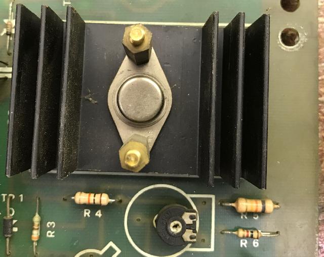
Power Supply High Voltage.
The 170 volts used for the score displays is generated by
a 2N3584 or TIP49 (or TIP48 or better TIP50) at TR1. Zaccaria used both devices interchangeably
on both gen1 and gen2 power supplies, as seen in the pictures below.
They also use two 2N3440 transistors at TR2/TR3.
Essentially this circuit is a loose copy of the Bally HV circuit
used on -17 and -35 games. So if you have parts to fix the Bally HV
circuit, you have many components for the Zac high voltage circuit too.
Like the Bally circuit, when there's a problem, the circuit
usually goes "high" (220 volts instead of 170 volts).
On gen1 power supplies there's also an adjustment pot (10k)
just below the 2n3584/TIP49 to dial in the voltage. This pot is
on the last portion of the HV circuit between the 170v output and
ground. On gen2 they just changed the 82k (gen1 R5) resistor to 100k (gen2 R10).
If you wanted to add an HV adjustment pot to a gen2 power supply you could.
It would involve changing R10 from 100k to 82k, and adding a 10k pot
between R8 and R10. Another way to adjust the HV on a gen2 power supply
without a pot is to just change R10 from 100k to say 90k.
Besides these three HV transistors (2n3584/TIP49 and 2n3440) that like to fail (in particular
the 2n3440 at TR3), there's resistor issues on these power supplies.
And on gen2 power supplies the R6 resistor 47ohms is *always* a problem.
Frankly I've never seen a gen2 power supply that did not have this resistor replaced!
This 47ohm 3watt resistor and it's always cooked.
Since it's an inline resistor, when it goes bad, the HV circuit dies.
So it's best to replace this with a 5watt resistor. You can even bump it
up to 50ohms or even 75ohms.
Always check the gen2 R3 resistor 22k ohm or R2 (gen1), because this is often a problem.
Also the gen2 R7 resistor 1k ohm or R6 (gen1) is a problem.
And the gen1 R5 resistor 82k ohm likes to fail.
Other resistors to check on gen2 power supplies include R8 (10k ohm)
and R10 (100k ohm) and R9 (4.7k ohm). In addition might as well check
R1 (100k ohm) and R4 (100 ohm) and R11 (1k ohm.)
TIP49 used for high voltage (gen1 power supply here, but used on
both gen1 and gen2 games).
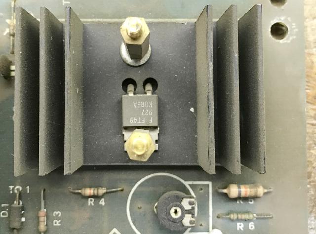
2n3584 used for high voltage on either gen1 or gen2 power supplies.
Either this or a TIP49 work fine here and are interchangeable.
Other things to look at are the DZ1 and DZ2 zener diodes. These are
70v-79v diodes 1/2watt that work together. Like the 140v zener diode
on a Bally HV power supply. But instead there's two here. These can
be replaced with 1n4760 diodes (68v at 1watt) or 1n4761 diodes (75v at 1watt.)
Unlike Bally HV power supplies, on gen2 power supplies there's an SCR1 which is a 2n6564.
This is a 400v SCR which is often replaced with an NTE5405 diode or a 2n5064 SCR.
Remember the 2n5064 is often used on Bally lamp driver boards.
Gen1 General Illumination Lighting and Processor Reset.
On gen1 games, the power supply's GI (general illumination)
power is also used for a reset varification.
Normally these two items (GI and reset) would not be tie together.
But it turns out that the GI circuit is critical to the
operation of these games - without it the game cannot boot.
The reason is that the bridge rectifier P3 on the power supply
board takes its AC input from the GI lamp circuit, and is labled
as being a +5.3VDC (VRM) power supply output. Tracing this through
the schematics, the only place it is used is to feed the Reset
circuit on the CPU board. Without a working GI power circuit,
the CPU cannot start, and the game will not boot. This makes a
bad connector problem at CN1 on the gen1 power suppy board a big problem.
It would affect the GI circuit input on the board, leading to
a non-working game when the CN1 connector fails.
Testing the Power Supply.
Before firing up the game, it's a good idea to remove all the conectors from
the left side of the power supply, and only leave connector CN1 attached (at
the bottom edge of the power supply). This is the AC connector from the
transforer. You can power the game on (assuming you have it jumpered correctly
for your line voltage), and check voltages. This is a really good idea
before actually trying to fire up the entire game.
With only connector CN1 attached, the power supply has test points (TP)
that can be checked. BUT the bummer is that Zaccaria often didn't install
wires at the test points! So installing test point wires is up to you!
But here's the voltages that should be checked for:
Gen1 Power Supply Test Points.
| Test Point |
Voltage |
Location |
Connector/Pin |
| TP1 |
170 vdc |
Top of Diode D1 |
CN6 pin 6 |
| TP2 |
5.3 vdc |
Right leg Resistor R8 |
CN6 pin 4 |
| TP3 |
12 vdc |
Left leg Cap C12 |
CN6 pin 3 |
| TP4 |
5.6 vdc |
Top Cap C6 |
CN5 pin 2 |
| TP5 |
-5 vdc |
Left leg Cap C9 |
CN6 pin 1 |
| TP6 |
39 vdc |
Top Resistor R7 |
CN3 pin 6 |
Gen2 Power Supply Test Points.
| Test Point |
Voltage |
Location |
Output Connector/Pin |
| TP1 |
170 vdc |
Above CN5 and left of large heat sink |
CN5 pin 8 |
| TP2 |
12 vdc |
Between large 10,000mfd caps |
CN5 pin 12 |
| TP3 |
5.6 vdc |
Right of CN5, under large heat sink |
CN5 pin 11 |
| TP4 |
5 vdc |
Top leg of R20 resistor, next to CN2 |
CN4 pin 1,2 |
| TP5 |
39 vdc |
Top of large R21 resistor, under bridge heat sink |
CN4 pin 3,4 |
| TP6 |
-5 vdc |
Between blue caps, under HV fuse F1. |
CN5 pin 10 |
| TP7 (power fail) |
5.6 vdc |
Right of CN5 |
CN5 pin 6 |
| TP8 |
Ground |
Bottom leg of R20 resistor, next to CN2. |
CN5 pin 2,3,4,5,7,9 |
Gen2 Power Fail White Wire (Power Supply CN5 pin6).
On gen2 power supplies, there's a small circuit that uses an LM339
voltage comparitor chip to create a "power fail" or "power failure" line. This is fed,
via a white wire from the power supply CN5 pin6,
to the CPU board at CN9 pin3 (which should show about 4vdc if the power fail circuit
is working.) If this power fail circuit is not working,
a Gen2 game will not boot. For this reason, you will often
see the white wire going from the power supply to the CPU board cut.
This "fixes" the issue, and will often let a gen2 game boot!
What you are really doing is avoiding the power supply's "power fail" circuit
when you cut the power supply CN5 pin6 white wire. The power fail section is
only used on Zaccarias gen2 power supply boards. This circuit checks
that correct voltage is supplied to the CPU board before the CPU boots up.
This is done through IC1 (LM339) and transistors TR4/TR5 (BC337) and TR6 (BC323),
and the capacitor C9 (1mfd.)
It is not uncommon for this power supply circuit to fail, and hence the game
won't boot (even though the power supply is otherwise good.) Again this is why
many people just cut the white CN5 pin6 wire, and call it a day.
But in reality the most common failure point is cap C9 (1mfd, ground lead closest to bridge rectifier.)
It likes to dry out and cause the power failure circuit to "fail." This happens because the
C9 cap is mounted right under the big heat sink, and the cap dries out.
In addition, transistor TR6 (BC323)
likes to fail too, as it is a 5amp NPN transistor, and hence it handles a bit of
current, thus it's death often occurs.
Note it is common to see TR6 replaced with a BC337 transistor. This is
probably bad behavior, since the TR6 handles some current. Just keep this in mind.
Initial Game Power Up.
If the output voltages are correct, turn the game off
and reconnect the wiring harness between the Power Supply and the CPU board.
Leave disconnected other connectors from the Power Supply to the Driver
board, and keep the cabinet/playfield disconnected. Also disconnect the ribbon cable
from the CPU board to the Driver board. Disconnect the connectors
from the CPU that go to the switch matrix (lower right side of the CPU board).
This leaves just the Power Supply and the CPU connected. Connect one score display
on the ribbon cable that goes to the backbox door, and remove the other displays
connectors (and Sound board connector). Try and power on the game and
see if the CPU board boots with a working score display. If this works,
the other score displays can be added. Do not power up the driver board
yet though, as there could be problems that result in causing other problems!
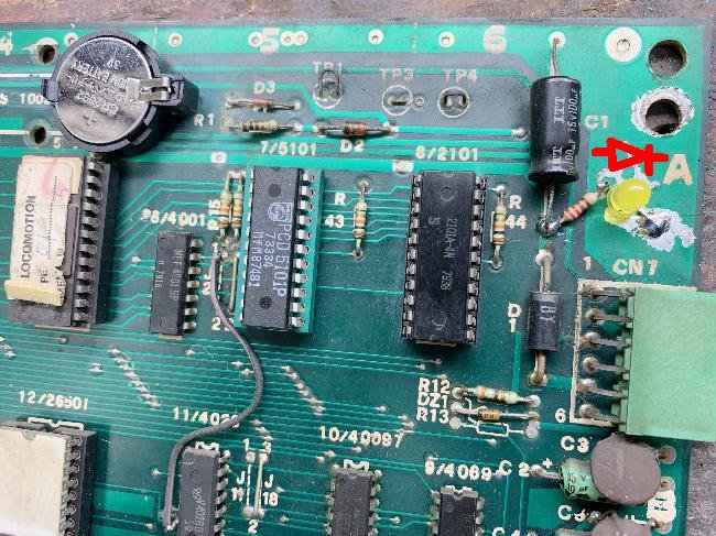
3b. Repair: Replacing the Battery and adding an LED (Gen1)
Zaccaria games like to have a valid battery on the MPU board. The original battery
was a re-chargeable type, much like used on Bally -17 and -35 games. These obviously
leak and can damage the MPU board (that's why we have a section on this repair above.)
But after you have the original battery removed and the corrosion (if any) dealt with,
what is the best substitute? Personally I like the CR2032 lithium coin battery approach.
Some people like memory caps, but my games aren't on often enough to keep that cap charged.
And re-programming a Gen1 game sucks, so to me, the memory cap idea is not good.
Since the original battery was a rechargeable type, you have to use a blocking
diode (to prevent charging) if you go with a CR2032 lithium. Not a big deal,
but just remember to do that! Don't try and charge a non-chargeable battery.
Only bad things can happen if you do that!
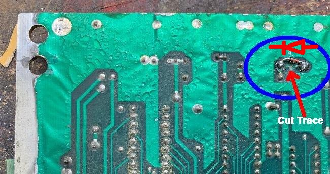
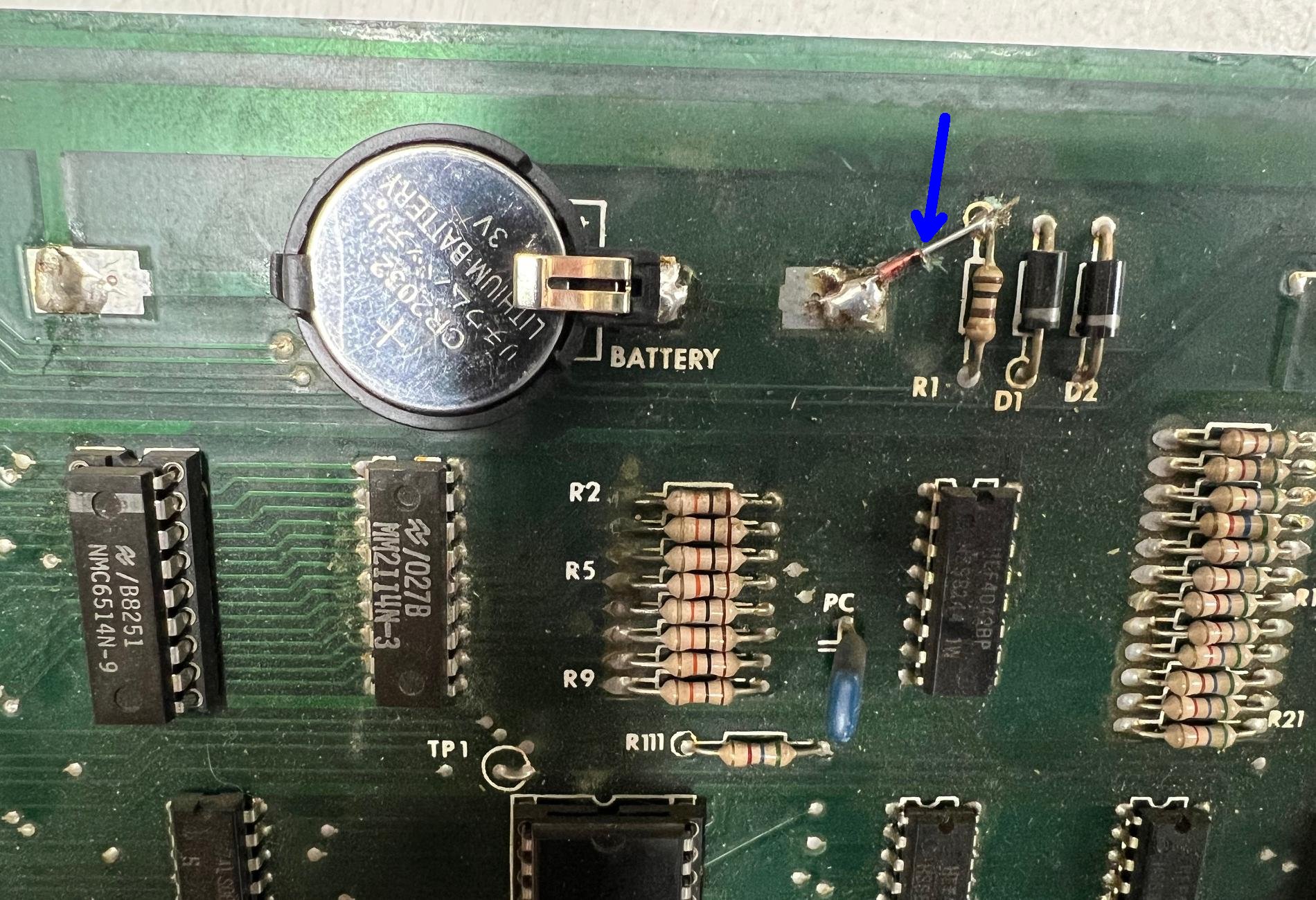
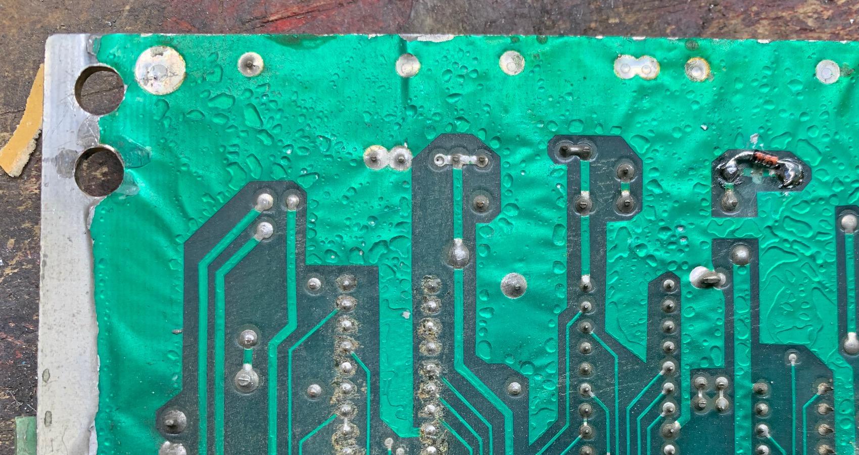
Back side: Gen1 Shoot the Rapids board with an added Lithium cr2032 coin battery.
Here a trace is cut, and an 1n4148 diode added as a blocking diode. This prevents
the lithium battery from being charged.
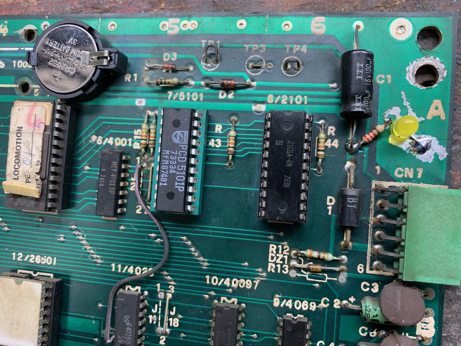
Front side: Gen1 Shoot the Rapids board with an added Lithium cr2032 coin battery.
Gen2 CPU board with CR2032 battery and 1n914 blocking diode. Note blue arrow shows trace cut under added diode.
Adding a Gen1 MPU Five Volt Indicator LED.
Another thing I like to add on Gen1 Zac MPU boards is a power-on LED. There's
absolutely no LED on the Gen1 mpu board (unlike Gen2 MPU boards.) So it's nice
to have a +5 volt indicator. I add this on the top edge of the MPU board.
Basically you take any standard LED and attach the flat side lead of the LED to
ground. Then the round side LED lead goes to a 220 ohm resistor. The other end
of the resistor attached to the positive leg of the C1 capacitor. See the picture
above.
3c. Repair: Gen1 MPU Setup
The gen1 Zaccaria MPU board is a strange animal. You *must*
run a battery for the 5-7 board position 5101 RAM chip. Why is this?
Because the game simply won't coin up if the memory settings
are not "set". Zac gen2 MPU boards don't have this weirdness, it's
only the Zac gen1 MPU boards that require this initial setup.
And if the battery isn't supplying power to the 5-7 board position
5101 RAM, then these setting will be lost at power off.
The trick is getting a gen1 game into the settings mode.
You would think just pressing the coin door diagnostic button
would do this... but you would be wrong! (This is not like
a Bally -17/-35.) Instead the procedure is as follows to
get a Gen1 game into setting mode.
- In attract mode, open the backbox and press the momentary
switch button on the top left of the MPU board.
- Press the coin door Diagnostic button (inside the coin door).
- The Match display should show "06". (Notice this is one past
the last diagnostic number of "05".)
- Use the game's Start button (credit button) on the front of
the cabinet to change the value for setting 06.
- After the setting is 'set', press the diagnostic button again
to move to the next setting number.
I should mention that the coin door and start buttons are pretty
sensitive in this setting mode. You have to press them very quickly,
or you will find you'll skip numbers. The setting are a linear
system, meaning you can go backwards! You can only advance the setting
number. To re-adjust a setting number lower than the current number,
you have to start over.
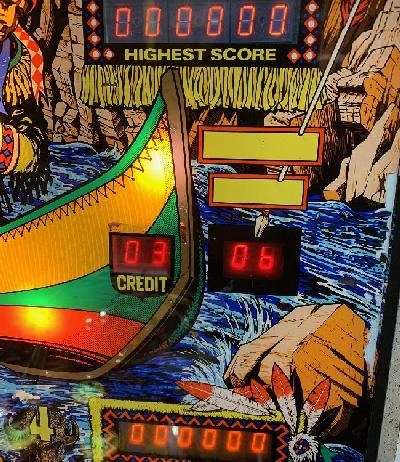
Gen1 Shooting the Rapids in the first adjustment #6 (number of balls=3).
Here's the typical list of Gen1 settings (number 06 to 26 in Match display)
that need to happen to make a game coin up. If you installed a new battery
with the power off, or a new 5101 RAM, these must be reset. If you don't
do this, chances are the game won't coin up and won't start.
Here's typical settings for most (all?) of the Gen1 Zaccaria games.
Use these as a default, and then refer to the manual and tweek them
as needed. (Things that tend to change between games are bonus ball
settings):
- Setting# = Value. (explanation)
- 06 = 03. Number of balls
- 07 = 01. Match off (00), or on (01)
- 08 = 01. Novelty (00), Replay (01), or Bonus ball (02)
- 09 = 15. Credit max: 10 to 60
- 10 = 01. Replay type: points (00), 1replay (01), 2replays (02), 3replays (03)
- 11 = 01. Always fixed (sempre fisso)
- 12 = 01. Coinage
- 13 = 01. Coinage
- 14 = 01. Coinage
- 15 = 01. Coinage
- 16 = 01. Coinage
- 17 = 01. Power on normal
- 18 = 01. Bonus ball (00), or replay (01)
- 19 = 00. Bonus ball/replay (00), or points (01)
- 20 = 01. Continuous sound. 00=no, 01=yes
- 21 = 00. Normal max score
- 22 = 00. High score obtained
- 23 = 50. bonus ball
- 24 = 66. bonus ball
- 25 = 00. bonus ball
- 26 = 00. Clear meters option. Press Start button to do this.
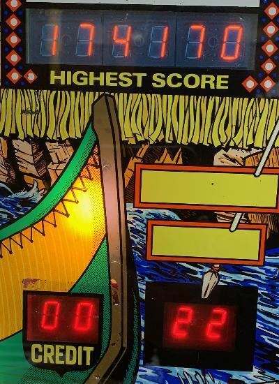
Shooting the Rapids adjustment #22 (high score obtained, shown int the high score display).
3d. Repair: Diagnostics
Zac diagnostics in general are pretty good. Especially the
gen2 diagnostics (with both a "test advance" and "test back" button,
so you can navigate the diagnostics in both direction.)
But the biggest bummer about Zac diagnostics are they are
part of the switch matrix! This is a really bad thing,
and most (all?) other manufacturers avoided doing this.
The reason is simple - if you do "blow up" the switch matrix,
you can still get into the diagnostic program to help
test the system. But with Zac, if the switch matrix
crashes, you're out of luck.
Gen1 Diagnostics.
When you press the Diagnostic button inside the coin door,
you will see the a "1" on the match number, and some
general game info in the other score displays. Press the
coin door diag switch again, and the diagnostics will begine
- Diag #1 - general game information, shown on the score displays.
d1=serial#, d2=won games, d3=played games, d4=coin1, d5=coin2, d6=coin3.
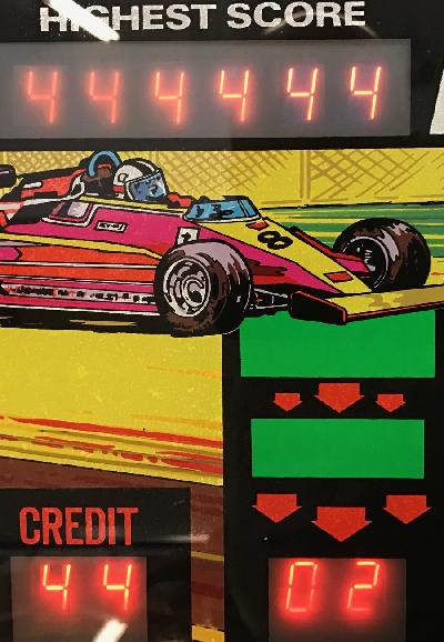
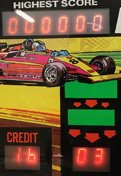
- Diag #2 - score display test. All displays advance from '111111' to '000000'
- Diag #3 - switch test (see the switch matrix charts elsewhere in this document)
- Diag #4 - lamp test. All cpu controlled lamps will toggle on and off
- Diag #5 - coil test. All coils will fire once in order. The coil number is
shown in the credit display. This will continually loop unless the Diag button
is pressed again, which will return the game to attract mode.
Gen1 Zac Hot Wheels in test#2 (score display).
Press the coin door diag switch again, and the switch
test will run (test#3).
Gen1 Zac Hot Wheels in test#3 (switches). Switch #16 is the outhole switch.
General Switch Numbers.
When using the switch test, there you should always refer to the switch
matrix chart for the particular game in question. But there are some
general switches that are nearly the same for all Zaccaria pinballs.
For Gen1 games, the standard switches are all in Row1 of the switch matrix (switches 00 to 07).
On Gen2 games, the standard switch are all in Row1 (switches 00 to 07)
and Row2 (switches 08 to 15) of the switch matrix.
Gen1 Zaccaria:
- self test
- tilt
- slam tilt
- credit (start) button
- coin switch#1
- coin switch#2
- coin switch#3
- not used
Gen2 Zaccaria:
- test adv
- test ret
- tilt2
- service credit
- coin switch#1
- coin switch#2
- coin switch#3
- not used
- not used
- credit (start) button
- tilt
- burn test
- not used
- not used
- not used
- not used
Switch Matrix Charts.
The following are documents showing the Zaccaria switch matrix for
gen1 and gen2 games.
Gen1 switch matrix charts
Gen2 switch matrix charts
Other Switch Matrix charts
If you want to change gen1 MPU settings, please see that section setup above.
3e. Repair: CPU Board Layout, Jumpers, ROMs
Gen2 CPU board
The acceptable Gen2 CPU board setup is to jumper the
board to use 2764 EPROMs. That makes the board most generic and
usable for any game. At the upper right of the CPU board is the red LED.
On a correctly booting board, it should turn on and stay on.
The Gen2 ROMs are located on the CPU board in the upper left corner.
Many Gen2 games use two ROM chips and have one unused socket pad.
Some games (like Pinball Champ) used three ROMs. The jumpers are directly
above the ROM sockets, and are used to select the size of the ROM chips installed.
Ideally it's best to configure ROMs and jumpers to use 2764 EPROMs. This makes
the CPU board most versatile.
Gen2 CPU and Sound board Jumpers, from the Pool Champs manual.
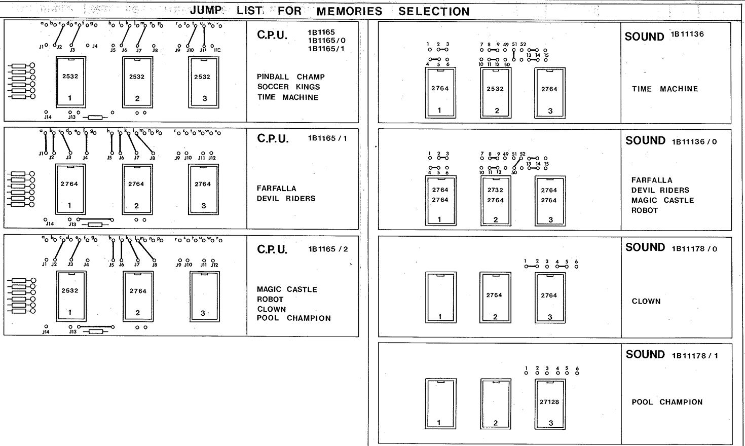
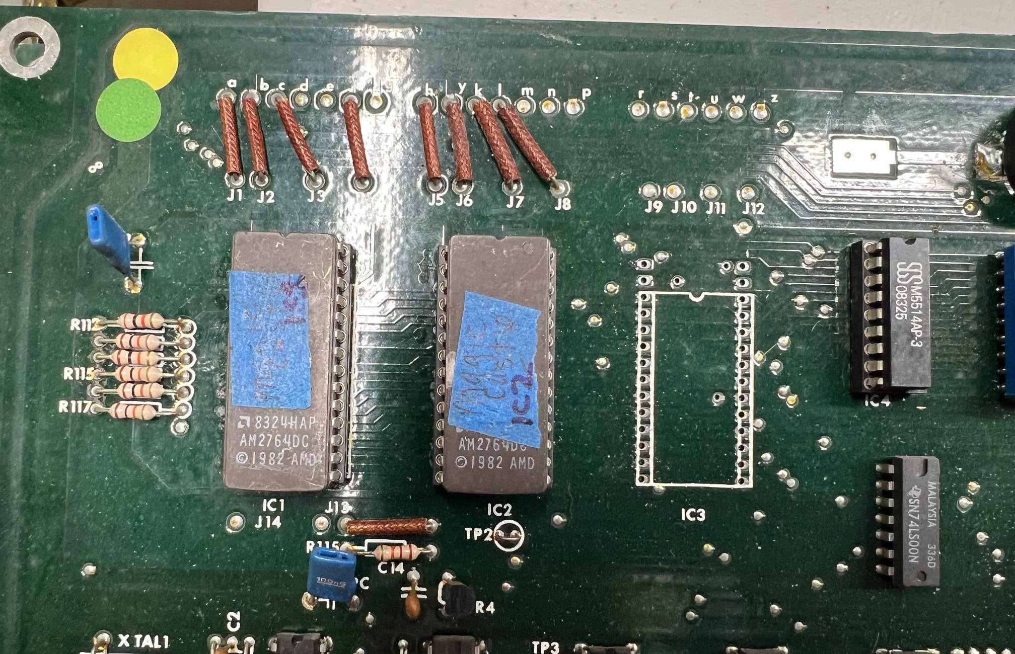
Gen2 ROM Jumpers for 2764 at IC1 and IC2 (usually Farfalla and Devil Riders):
All other jumpers not connected (J9,J10,J11,J12).
- J1 to a
- J2 to b
- J3 to c
- J4 to f
- J5 to h
- J6 to i
- J7 to k
- J8 to l
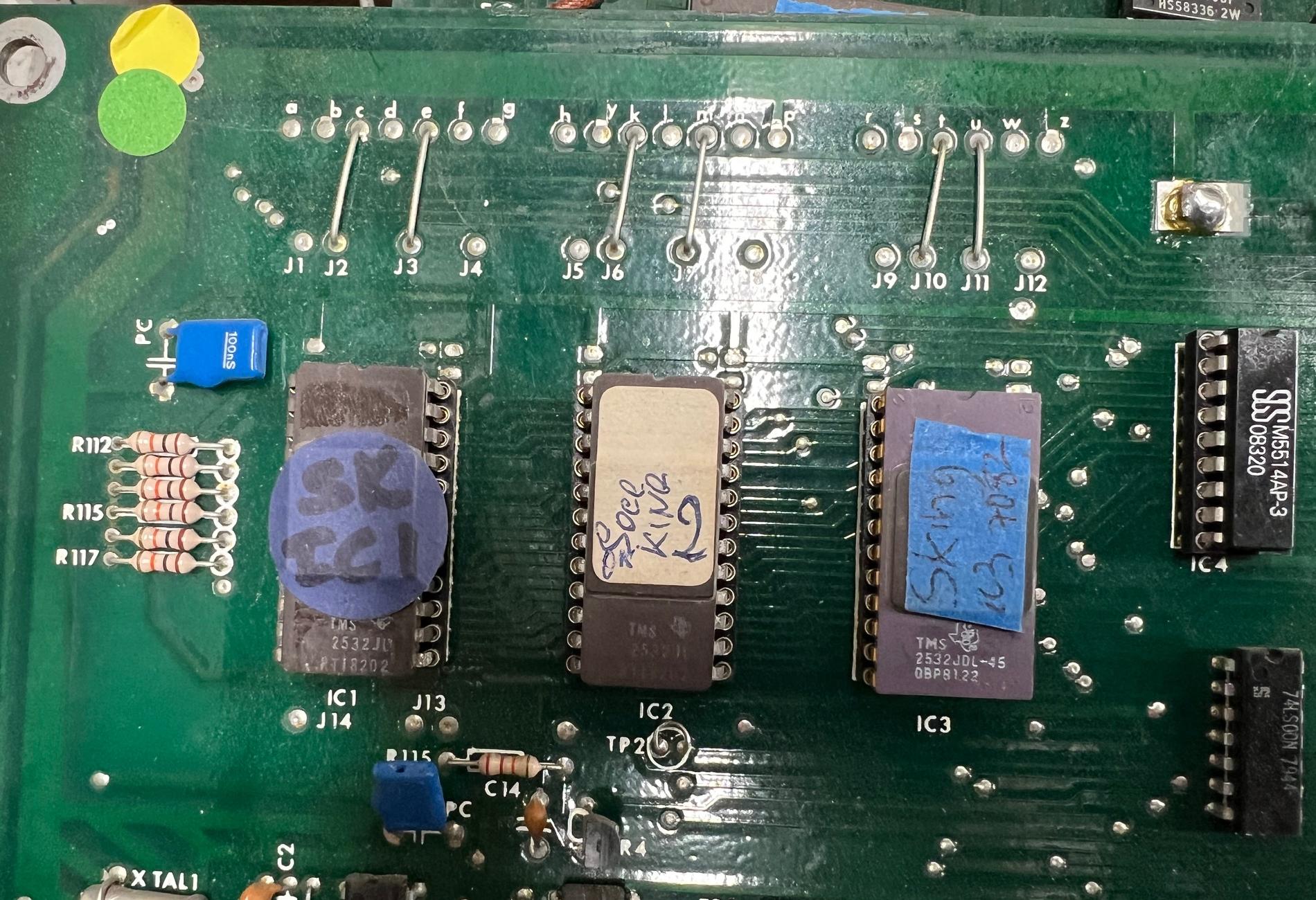
Gen2 ROM Jumpers for 2532 at IC1, IC2, IC3 (usually Soccer Kings, Pinball Champ, Time Machine):
All other jumpers not connected (J1,J4,J5,J8,J9,J12).
- J2 to c
- J3 to e
- J6 to k
- J7 to m
- J10 to t
- J11 to u
Gen2 ROM Jumpers for 2532 at IC1 and 2764 at IC2 (usually Magic Castle, Robot, Clown, Pool Champion):
All other jumpers not connected (J1,J4,J9,J10,J11,J12).
- J2 to c
- J3 to e
- J5 to h
- J6 to i
- J7 to k
- J8 to l
Gen2 CPU board set for 2764 EPROMs at IC1 and IC2 (Magic Castle)
Gen2 CPU board set for 2532 EPROMs at IC1, IC2, IC3 (Soccer Kings)
The RAM and CMOS are at IC4 and IC5, directly beneath the battery,
and to the right of the ROM chips. These are the first two things
to be damaged with battery leakage. IC4 is a 6414 (can substitute 5514 or 6514), and
IC5 is a 2114 RAM (can substitute 9114).
The Battery is at the top center of the board. I replace the original battery with a
non-rechargable Lithium cr2032 battery, and a 1n914 blocking diode (to prevent charging the battery.)
Below and to the right of the RAM chips is a large Signetics 2650A CPU chip.
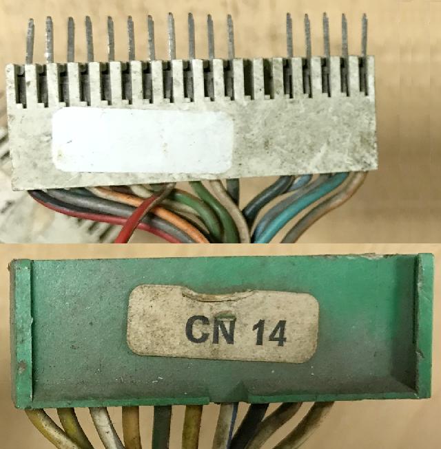
On the left edge of the board is a ribbon connector CN14 for the displays.
The logic chips and components to the right of this connector are the display memory and controls.
At the bottom of the CPU board is ribbon connector CN12 to the Driver board.
The ribbon cable connector CN8 on the right edge goest to the Sound board.
The logic chips and components to the left of this connector drive the sound board.
Gen2 power connector CN9.
CN9 has four pin .156" pins on the right side of the board,
under the sound ribbon cable connector. The power cable layout top to bottom
(with the top most pin being pin1):
- Pin 1 - 170vdc display voltage (yellow wire)
- Pin 2 - Ground (black wire)
- Pin 3 - Power Good 4.5 to 5.0vdc (white wire)*
- Pin 4 - +5vdc, actually 5.5 to 5.9vdc (red wire)
* Note it is common to see the white "power good" wire cut. This circuit
on the power supply board if often failed, and it will stop the CPU board
from booting. As a short cut, often operators will just cut the white wire
to get the game running. It's not suggested behavior, but it's common to see.
The best approach is to repair the power supply board (there's an LM339 chip
in this circuit), as the "power good" line was designed in the circuit to
prevent problems.
The connector CN10 is the Switch Matrix columns, right side of the CPU board beneath the power plug.
Likewise connector CN11 is the (Switch Matrix row.
The DIP switches are used to enter setup mode and set the default pricing and operator settings,
when the CMOS RAM settings are detected to be invalid (dead battery.) This feature seems
only to be intended to allow the game to still make money on location, even if the settings
are not correct. Normally all four switches should be set to "off".
Note SW4 is used to enter setup mode; switches 1,2,3 all set the country-specific default pricing scheme.
Gen2 Test Points.
Below are the Gen2 CPU board test points, and what they should be doing on a booting CPU board in attract mode.
This is helpful to know if you are booting a CPU board on the bench without score displays connected.
- TP1 = HIGH (CPU Pin 1 - Sense)
- TP2 = Pulsing (CPU Pin 38 - Clock)
- TP3 = Pulsing (Interrupt Generator)
- TP4 = LOW (CPU Pin 16 - Reset)
- TP5 = HIGH / Pulsing (CPU Pin 17 - Intreq)
- TP6 = Pulsing (Out Counter)
- TP7 = LOW (Out Counter)
- TP8 = LOW (Voltage Good)
- TP9 = LOW / Pulsing (Clock oscilator output)
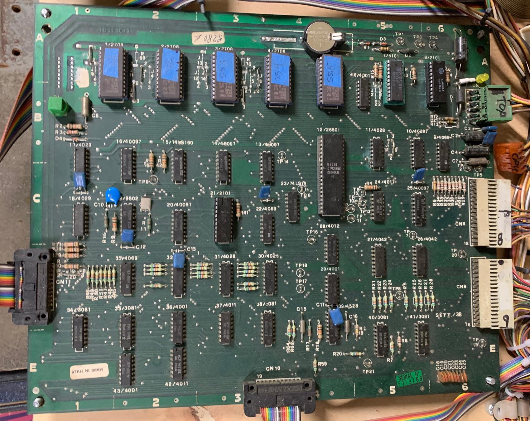
Gen1 CPU board.
Gen1 CPU boards are quite different. Remember the main difference
between gen1 and gen2 CPU boards (besides connector types) are
ROM space. The gen1 boards use five 2708 EPROMs, with the last few
games using up to two 2716 EPROMs and three 2708 EPROMs.
So why does that matter? Well besides the limited programming
space, 2708 EPROMs require *three* voltages to work: +5 volts, +12 volts,
and -5 volts. This is why the gen1 CPU board has all these voltages
coming to the board (unlike gen2 CPU boards that will run just on +5 volts.)
Gen1 games in chronological order...
- Winter Sports. CPU board uses five 2708 EPROMs.
- House of Diamonds. CPU board uses five 2708 EPROMs.
- Future World. CPU board uses five 2708 EPROMs.
- Shooting the Rapids. CPU board uses five 2708 EPROMs.
- Hot Wheels. CPU board uses four 2708 EPROMs and one 2716 EPROM at IC1.
- Fire Mountain. CPU board uses four 2708 EPROMs and one 2716 EPROM at IC1.
- Star God. CPU board uses four 2708 EPROMs and one 2716 EPROM at IC1.
- Space Shuttle. CPU board uses four 2708 EPROMs and one 2716 EPROM at IC1.
- Earth Wind Fire. CPU board uses four 2708 EPROMs and one 2716 EPROM at IC1.
- Locomotion. CPU board uses three 2708 EPROMs and two 2716 EPROM at IC1/IC3.
Gen1 MPU Board Revisions.
The first MPU for Gen1 games was MPU Board 1B1110. It used five 2708 EPROMs
at location IC1-IC5 (labeled as "1/2708" to "5/2708"). This board was used on
four games (Winter Sports, House of Diamonds, Future World, Shooting the Rapids.)
The next MPU board is 1B1110/0. It uses four 2708 EPROMs and one 2716 EPROM at IC1.
This board is used on three games (Hot Wheels, Fire Mountain, Star God.)
The increased ROM space (2716) at IC1 was required for these three games.
As part of the changes to support a larger ROM (2716) at IC1, and
to make the board backward compatible with the earlier 1B1110, jumpers J17 and J18 were added.
Jumpers J17/J18 control where in the address space ROM2 appears by changing its Chip Select
from IC11 out line 1 to IC11 out line 7. The other change to 1B1110/0 is a "clear CMOS RAM" feature.
This allows the game to ignore and clear the contents of the 5101 RAM (the battery backup RAM),
if powered up with TP19 (Switch Matrix Row 1) is connected to TP20 (Switch Matrix Column 0).
Note these two test points are located by MPU connector CN9.
This was allows the user to clear a flakey 5101 CMOS RAM chips and/or failing batteries (which power
the 5101 RAM when the game is off, so it doesn't forget audit and settings information).
This is handy because bad data in the 5101 RAM can cause strange game behavior,
and on earlier games could simply crash the MPU board or even make it fail to boot.
Next was MPU board 1B1110/1. Used on Space Shuttle and Earth Wind Fire,
it has the same ROM space as 1B1110/0. But this new MPU board introduced Switch Matrix Row 7.
On the earlier MPU 1B1110 and 1B1110/0, the switch matrix connector CN9 pin 9
did not go anywhere. On the newer MPU 1B1110/1, switch matrix CN9 pin 9 is connected to IC26 pin 7.
This, and the previously unused Switch Matrix Row 6, are used to support the 1B1149 "Flipper Programming Board".
To be honest, this is the only reason for switch matrix row 7. No (as in none!) Gen1 games
use switch matrix row6 or row7! So really the difference between 1B1110/0 and 1B1110/1 is not important.
But hey if for some reason you want switch matrix row7, the 1B1110/0 could be modified by adding a
jumper from IC26 pin 7 to CN9 pin 9.
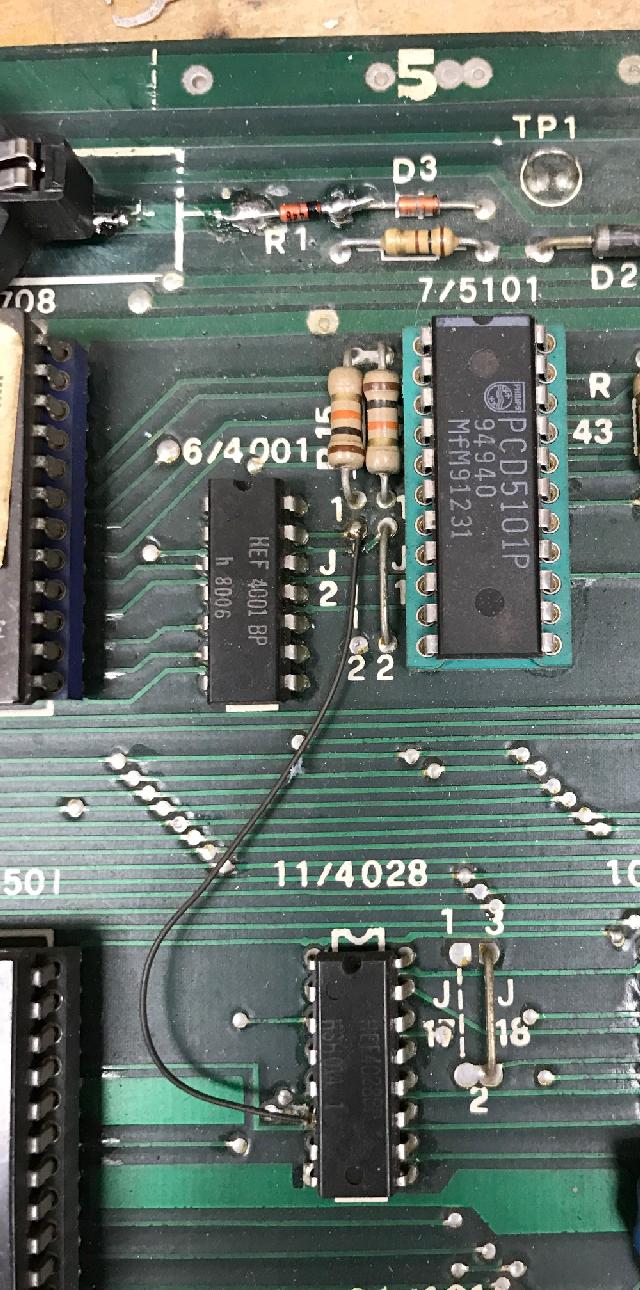
Finally, the 1B1110/1a was the last update to this board, which is just a modified
MPU 1B1110/1 design to allow a second 2716 EPROM.
This board was used only for Locomotion, their last 1st generation game.
It's feature allows a 2716 EPROM at IC3 (instead of 2708.) This was needed for Locomation, as they
needed more programming space. To support a 2716 EPROM at IC3,
they cut the trace at IC11 pin 6 (which formally connected to IC39 pin 12), and connected it
with a jumper wire to Jumper J2's pin 1. Also IC39 pin 12 was connected with
a jumper wire to IC12 pin 18 (CPU address line 14). This placed
the upper half of the IC3 2K 2716 EPROM above the data from the EPROM IC5 in the
address space. Without these modifications, the upper half of ROM3 (a 2716 EPROM) is not addressable.
Note that the 1B1110/0 and 1B1110/1 are the most useful and versatile of the four Gen1 MPU board revisions,
since they have the RAM reset feature (and can support Switch Matrix Row 7, though frankly, that is
really not important, since no games use switch matrix row7!) These two boards would work for
any Gen1 game except for Locomotion. If needed for a Locomotion, either 1B1110/0 or 1B1110/1
can be modified into a 1B1110/1a.
Converting Gen1 CPU board to all 2716 EPROMs.
There is a couple ways to modify your Gen1 MPU board 1B1110/0, 1B1110/1 or 1B1110/1a to use 2716 EPROMs.
Why use 2716 EPROMs instead of 2708 EPROMs?
Personally I like the "all 2716 conversion" as you can have all the Gen1 games set up
in 2716 EPROM format, as 2708 EPROM are difficult to program for most EPROM programmers.
This is because most EPROM programmers can't handle all three voltages needed for a 2708
(+5, +12 and -5 volts) to run. Also as has been documented, there's a mix of EPROM sizes used
on different Gen1 games. If you have everything set up for 2716 format, you can change
a CPU board easily between any of the Gen1 games without doing any jumper modifications.
Say you want Futureworld... just install all 2716 EPROMs in the sockets and you're done.
You want Locomotion, again just install all 2716 EPROMs and you're done. Easy and convertable!
This solution uses a "double up" ROM technique to get
the 2708 ROM files on the computer into 2716 EPROM format. Since 2716 EPROMs only
require +5 volts to work on the CPU board, -5 and +12 volts is no longer needed on the CPU board.
Note this makes it a lot easier to bench test an MPU board too, as you now only need +5 volts for power.
To do the 2716 conversion, you'll first need to get your ROM files in order,
using a DOS command (at the "C:>" DOS prompt)
on the original 2708 images, converting them to 2716 sized files:
copy /b romfile1.708 + romfile1.708 romfile2.716
What this is doing is using the DOS "copy" command with the "/b" (binary)
copy option, and copying the same file twice, into a final 2716 file that
is twice the size of the original 2708 file. Obviously for games that use
some 2716 ROMs (like say Locomotion or Space Shuttle), you don't need to do
this for the files already in 2716 format.
After all five files are in 2716 format and burned into five 2716 EPROMs,
they can be installed directly into the CPU board. BUT the -5 and +12 volts coming into
the board has to be disconnected. If the CPU board is powered up with -5 and +12 volts going
to the new 2716 EPROMs, these voltages will ruin the 2716s. So the CPU board has to have
a slight modification so that the -5 volts and +12 volts (which is only used to power
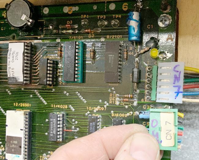
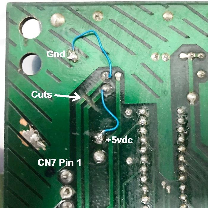
2708 EPROMs) is disconnected. To do this the CPU board's power at connector CN7 is modified
right on the CPU board:
- CPU connector CN7 pin 6 (usually white wire) needs to be cut and tied to ground.
- CPU connector CN7 pin 4 (usually red wire) needs to be cut and tied to +5 volts
(top lead of the large diode by connector CN7).
With this modification, all five EPROMs can now be run as 2716 EPROMs.
NOTE: You do *not* need to change the ROM jumpers from "stock" for your particular game set up.
For example, if you're running Locomotion (which uses three 2708 EPROMs and two 2716 EPROMs
in stock format, and will now be all 2716's), do not need to change the ROM jumper settings from stock.
BUT if you want your Gen1 CPU board to be the most versatile, change the CPU board jumpers to
Location style. This will allow you to use any game with all 2716 EPROMs with no jumper changes.
A modified Gen1 CPU board to use all 2716 EPROMs (no 2708).
Locomotion Gen1 CPU Board Jumpers.
When converting a gen1 1B1110/1 (Space Shuttle and earlier) to a 1B1110/1a for Locomotion,
some jumper changes are needed. Remember they increased the ROM space to use two 2716 EPROMs instead
of 2708 EPROMs on Locomotion. Again if you're using all 2716 EPROMs, regardless of the game,
these jumper changes make your Gen1 CPU board the most versatile. (That is, you can
install *any* game's EPROMs into the board without jumper changes, assuming all EPROMs
are in 2716 format.) These changes include:
- Cut the trace at IC11 pin 6.
- Jumper IC11 pin 6 to J2 pin 1
- Jumper IC39 pin 12 to IC12 pin 18
- Do not install jumper J2
Converting One 2708 socket to 2716.
Alternatively, one ROM can be converted to 2716 only. To do this, the
socket that is being converted from 2708 to 2716 is modified.
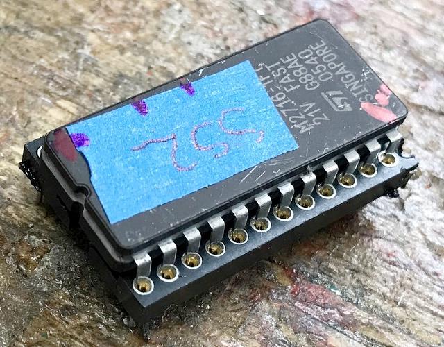
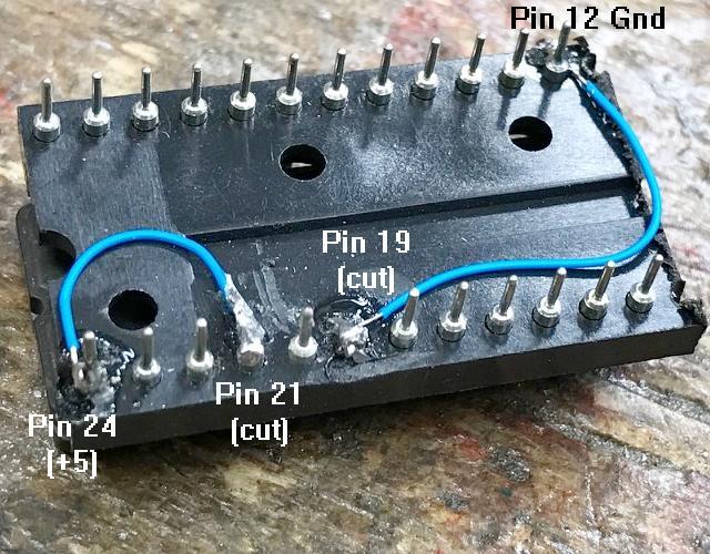
Burn the new 2716 and install it in the socket of choice. But make this modification:
- Bend the 2716's pin 19 out of the socket. Connect the bent out 2716 EPROM pin 19 to ground.
- Bend the 2716's pin 21 out of the socket. Connect the bent out 2716 EPROM pin 21 to +5 volts.*
Then the CPU connector CN7 (power in) is not changed (left in its original configuration).
The best way to do this conversion is to plug the 2716 EPROM into a separate socket, and
modify the socket. Then plug the EPROM/socket into the existing CPU board socket,
the board itself is not modified. Note on a 2716 EPROM, ground is pin 12 and +5 (vcc) is pin 24.
Using a 24 pin socket modified to use a 2716 EPROM in place of a 2708 (top).
Using a 24 pin socket modified to use a 2716 EPROM in place of a 2708 (bottom).
* In addition, if you prefer to use a 2732 (instead of a 2716), this can be done easily too.
Do the above modification, but on the 2732 pin 21, connect that to ground (instead of +5 volts).
Note you'll need to "quad up" the ROM files to use a 2732 EPROM (as described above
where we "doubled up" the 2708 ROM file into 2716 ROM file format.)
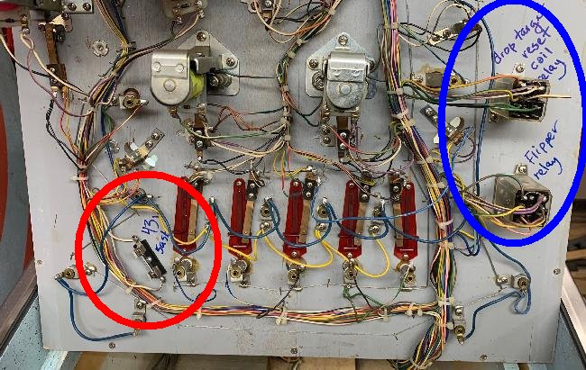
3f. Repair: Under-PF Relays
Some Gen1 games (and perhaps Gen2) use under playfields relays.
Below is a picture of a gen1 Shooting the Rapids. It has two
under playfield relays - the flipper relay (engages when a game
is started), and a relay for the drop target reset coils. Since
on Shooting the Rapids the drop target bank is long, it required
two coils. So Zaccaria decided to use a relay to reset the drop
target bank. A driver transistor on the driver board triggers
the relay, and the relay fires the two drop target coils (to
reset the drop target bank.)
Shooting the Rapids under the playfield. On the left, in a red
arrow, is the playfield coil fuse. On the right are two relays.
One for the flippers, and the other for the drop target reset bank.
3g. Repair: Switch Matrix
The switch matrix is handled by the CPU board. It uses eight row and eight columns.
Problems with the switch matrix are very common in Zaccaria games (both gen1 and gen2.)
This is probably due to someone working on a game, and shorting coil voltage to
a switch lug.
The big problem with the Zac switch matrix is the Advance Test (and Return Test) buttons
are part of the switch matrix (row0/col0 and row0/col1.) This is a major design no-no
in the pinball world. Because if the switch matrix does take a dump, there's no way to
put the game into diagnostic tests! Most pinball game makers, for this reason, do not have
the test function as part of the switch matrix. Unfortuantely, Zaccaria didn't do that,
and if you have a switch matrix issue, there's just no way to get the game into diagnostics.
Hence having a switch matrix problem is very fustrating. Luckily fixing
the switch matrix *usually* isn't too big of a deal.
Though all games don't use all switches, there is a possibilty of 64 switches through
the use of 8 rows and 8 columns. This is pretty standard pinball stuff as far as that goes.
Notice the numbering of the rows and columns starts with "0" (opposed to "1"), which
means the guy designing the system was a true computer geek. Note that Gen1 games
do not use Row6 or Row7 on any game (row7 isn't even listed on the gen1 schematic
until Space Shuttle.)
Here's the CPU board connectors that attach to the playfield and cabinet switches.
Note on the gen2 CPU board connector CN10 is for the cabinet switches, and connector CN11 is
for the playfield switches. On gen1 CPU boards, CN9 is for the cabinet switches and CN8 is for
the playfield switches.
Gen1 Switch Matrix Column Connectors
| Column | Connector | Usage | | Connector | Usage | Chip |
|---|
| Column 0 | CN8 pin 10 | cabinet | | CN9 pin 10 | playfield | ic10 p2 |
| Column 1 | CN8 pin 11 | cabinet | | CN9 pin 11 | playfield | ic10 p4 |
| Column 2 | CN8 pin 12 | cabinet | | CN9 pin 12 | playfield | ic25 p2 |
| Column 3 | CN8 pin 13 | cabinet | | CN9 pin 13 | playfield | ic25 p4 |
| Column 4 | CN8 pin 14 | cabinet | | CN9 pin 14 | playfield | ic25 p6 |
| Column 5 | CN8 pin 15 | cabinet | | CN9 pin 15 | playfield | ic25 p10 |
| | CN8 pin 16 | | | |
| Column 6 | CN8 pin 17 | cabinet | | CN9 pin 16 | playfield | ic25 p12 |
| Column 7 | CN8 pin 18 | cabinet | | CN9 pin 17 | playfield | ic25 p14 |
Gen1 Switch Matrix Row Connectors
| Row | Connector | Usage | | Connector | Usage | Chip |
|---|
| Row 0 | CN8 pin 6 | Cabinet | | CN9 pin 1 | playfield | ic40 p1 |
| Row 1 | CN8 pin 7 | Cabinet | | CN9 pin 2 | playfield | ic41 p7 |
| Row 2 | CN8 pin 8 | Cabinet | | CN9 pin 3 | playfield | ic41 p4 |
| Row 3 | CN8 pin 9 | Cabinet | | CN9 pin 4 | playfield | ic41 p3 |
| Row 4 | | | CN9 pin 5 | Playfield | ic41 p1 |
| Row 5 | | | CN9 pin 6 | Playfield | ic41 p14 |
| Row 6* | | | CN9 pin 7 | Playfield | ic41 p12 |
| | | | CN9 pin 8 | | ic41 p9 |
| Row 7* | | | CN9 pin 9 | Playfield | ic26 p15 |
|
* Row6 and Row7 is not used on any Gen1 Zaccaria game.
Gen2 Switch Matrix Column Connectors
| Column | Connector | Usage | | Connector | Usage | Chip |
|---|
| Column 0 | CN10 pin 10 | cabinet | | CN11 pin 10 | playfield | ic25 p2 |
| Column 1 | CN10 pin 11 | cabinet | | CN11 pin 11 | playfield | ic25 p4 |
| Column 2 | CN10 pin 12 | cabinet | | CN11 pin 12 | playfield | ic25 p6 |
| Column 3 | CN10 pin 13 | cabinet | | CN11 pin 13 | playfield | ic25 p10 |
| Column 4 | CN10 pin 14 | cabinet | | CN11 pin 14 | playfield | ic25 p14 |
| Column 5 | CN10 pin 15 | cabinet | | CN11 pin 15 | playfield | ic25 p12 |
| | CN10 pin 16 | key | | |
| Column 6 | CN10 pin 17 | cabinet | | CN11 pin 16 | playfield | ic24 p14 |
| Column 7 | CN10 pin 18 | cabinet | | CN11 pin 17 | playfield | ic24 p12 |
Gen2 Switch Matrix Row Connectors
| Row | Connector | Usage | | Connector | Usage | Chip |
|---|
| Row 0 | CN10 pin 6 | cabinet | | | TR3 |
| Row 1 | CN10 pin 7 | cabinet | | CN11 pin 2 | playfield | ic38 p1 | |
| Row 2 | | | CN11 pin 3 | playfield | ic38 p2 |
| Row 3 | | | CN11 pin 4 | playfield | ic38 p14 |
| Row 4 | | | CN11 pin 5 | playfield | ic38 p4 |
| Row 5 | | | CN11 pin 6 | playfield | ic38 p12 |
| Row 6 | | | CN11 pin 7 | playfield | ic38 p7 |
| Row 7 | | | CN11 pin 8 | playfield | ic38 p9 |
|
The column/row layout is done above for a reason. The cabinet switches (test, start, coin, etc)
are all in row0 and row1. Hence gen2 Connector CN10 is wired as it is (it's the cabinet switch matrix
connector.) Where gen2 CN11, the playfield switch connector, does not have any Row0 reference (because
all Row0 switches are cabinet switches.) The row0 and row1 layout is consistent amoung all
Zaccaria games (within Gen1 and Gen2, which have some slight variations):
Gen1 Row0-Row2 Switch Matrix
| |
Col0 |
Col1 |
Col2 |
Col3 |
Col4 |
Col5 |
Col6 |
Col7 |
| Row0 |
00: Test
| 01: Tilt1
| 02: Tilt2 |
03: Credit |
04: Coin1 |
05: Coin2 |
06: Coin3 |
07: |
| Row1 |
08: Ram Reset
| 09:
| 10: |
11: |
12: |
13: |
14: HS reset |
15: Burn Test |
| Row2 |
16: Outhole
| ...
| ... |
... |
... |
... |
... |
|
Gen2 Row0-Row2 Switch Matrix
| |
Col0 |
Col1 |
Col2 |
Col3 |
Col4 |
Col5 |
Col6 |
Col7 |
| Row0 |
00: Test Adv
| 01: Test Ret
| 02: Tilt2 |
03: Serv Credit |
04: Coin1 |
05: Coin2 |
06: Coin3 |
07: |
| Row1 |
08:
| 09: Credit
| 10: Tilt1 |
11: Burn Test |
12: |
13: |
14: |
15: Print |
| Row2 |
16: Outhole
| ...
| ... |
... |
... |
... |
... |
... |
Switch Matrix Charts.
The following are documents showing the Zaccaria switch matrix for
gen1 and gen2 games.
Gen1 switch matrix charts
Gen2 switch matrix charts
Other Switch Matrix charts
Note that switch #16 (row2, col0) is the outhole switch. That is pretty
consistent on all Zaccaria games. Also notice the "print" switch. You can
actually hook up a custom receipt-like printer to Zaccaria gen2 games (which was
available from Zaccaria), through a printer port near
the coin door on some Gen2 games. I don't have much detail on that, but it's a neat feature (assuming
you had a portable printer back in the 1980s!) This feature was only on Gen2 games
and was abandoned after Soccer Kings.
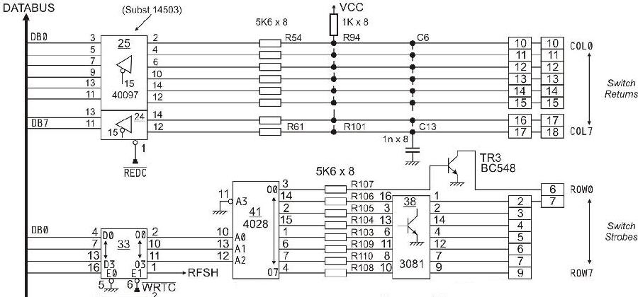
On Gen2 games most switch matrix row problems are a blown CA3081 chip at ic38 (and/or the BC548 transistor at TR3).
On Gen1 games most switch matrix row problems are a blown CA3081 chip at ic40 and/or ic41.
On Gen2 games, the switch matrix especially goes south on the games with stacked flipper EOS switches
like Farfalla, Magic Castle, Devil Riders. This happens
because there's coil power (39V) and lane change (switch matrix) on the EOS switch stack.
Then a CA3081 chip dies when somebody tries to
adjust the EOS switch with the power on, shorting coil voltage to the switch matrix
lane change switch..
The failure point is usually the CA3081 transistor array
chips at IC38 on the CPU board for the rows. But it doesn't end there. The
problem can back up to the 4028 chip behind it at IC41, It can even go one step
further back to the 4042 chip at IC33 (this especially likes to happen if
someone shorts 160 volt score display voltage to the switch matrix, which
can happen!) Note the transistor TR3 (BC548) is responsible for row0,
and it can fail too, causing some weird behavior. Replace only with a BC548,
do not use a 2n3904.
As for the switch columns, less problems generally happen here. But on Gen2 games the 40097 (4503) chip
at IC25 can be a problem. On Gen1 games the switch columns use 40097 chips at ic10 and/or ic25.
But in my experience, the row path is generally the one
with more issues.
Zaccaria Gen1 switch matrix schematic for the rows and columns.
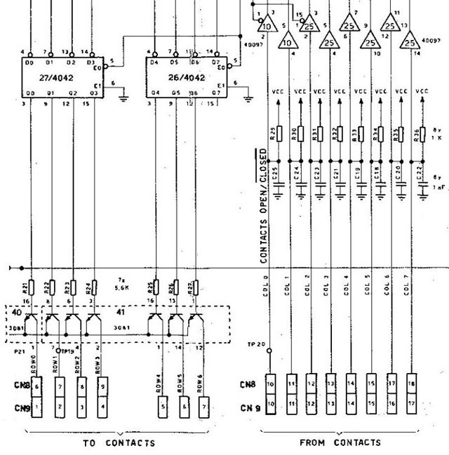
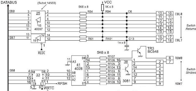
Zaccaria Gen2 switch matrix schematic for the rows and columns.
After the above paths are checked, everything backs up via the DB0-DB7 lines to the
2650 processor at pins 33-26 (respectively.) Note the RAM chips (6514 and 2114) at
IC4 and IC5 also share the DB0-DB7 lines. But if the game is running and in attract
mode, chances are pretty good the RAM chips are fine.
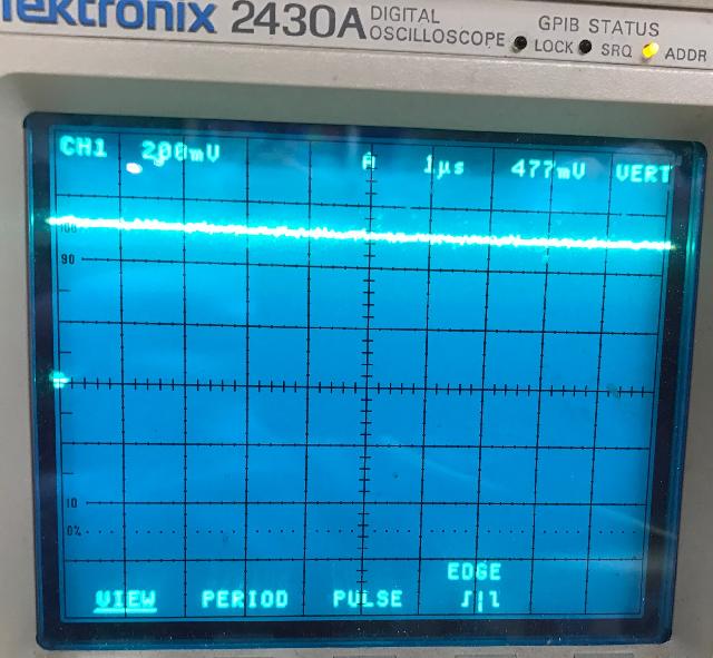
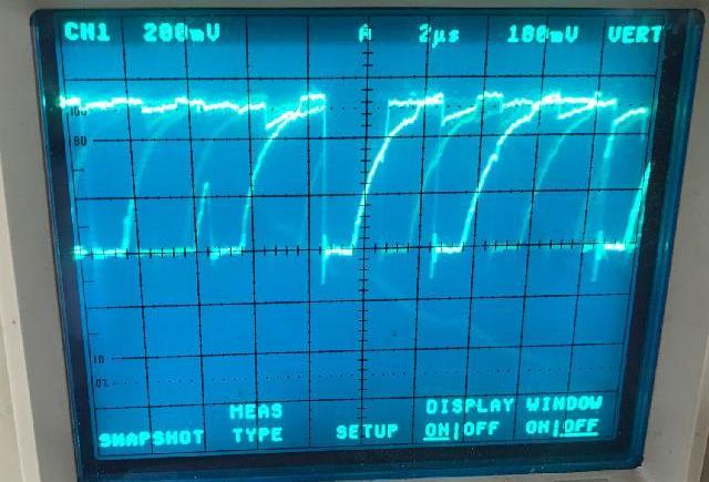
Oscilloscope Pictures of the Switch Matrix.
The following pictures shows how the switch matrix looks on an oscope
on a working Gen2 CPU board (Magic Castle) jumpered for two 2764 EPROMs in attract mode.
This may be important in diagnosing a switch matrix problem.
Note these pictures used a Tektronix 2430 digital oscope. I tried to be as consistent
as possible with the width (time) and height (voltage) of the wave forms.
But this is not always possible, depending on the signal.
Let's start with the switch matrix columns, as that path to the 2650a processor
is much shorter. The columns is the switch matrix "power" (drive), so it's
not as easy to see things on the scope because of this. Frankly you're looking
at the pull-up resistors r54-r61 when putting the scope on the switch column
connector (or the right side of chip ic25). On the left side of ic25 you're
looking at the data buss, which probably isn't that helpful either. But we'll
start here with some oscope pictures, to get you warmed up.
Let's look at the switch column path.
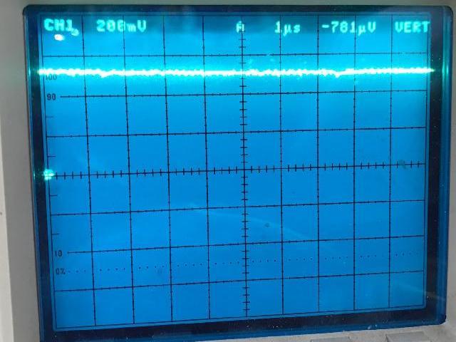
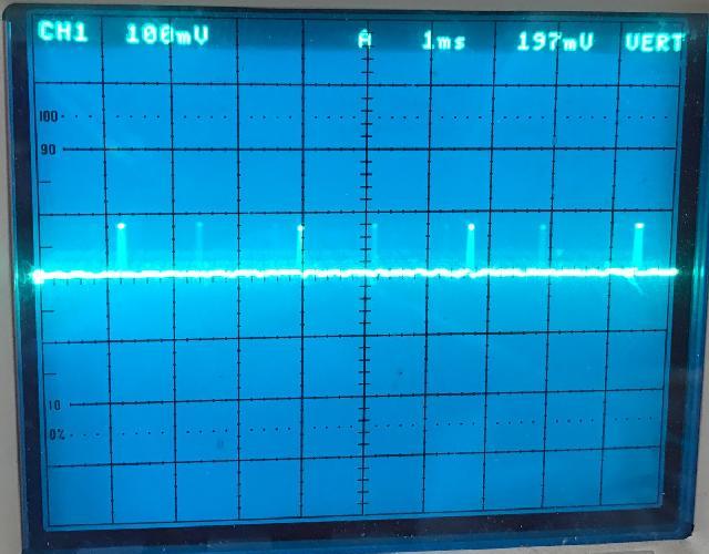
Switch matrix column0 on connector cn11 pin 10, with game in attract mode. Note
that CN11 pin 10 to pin 17 (col0 to col7) should all look like this. What you're
really seeing is just +5 volts through the pull up resistors at r54-r61:
Switch matrix column, back one level, to IC25 pin 2 (column0). Note
that the other switch columns at IC25 pins 2,4,6,10,14,12 and IC24 pin 14,12.
It should look like this:
Switch matrix column, back one more level, to IC25 pin 3 (the left side of ic25).
It should look the same as IC25 pins 5,7,9,13,11 and IC24 pins 13,11.
What you're looking at here is the data buss DB0-DB7, which is shared with
the ROMs and RAMs. This then feeds back to the 2650 processor. This is probably not that
helpful, but here it is:
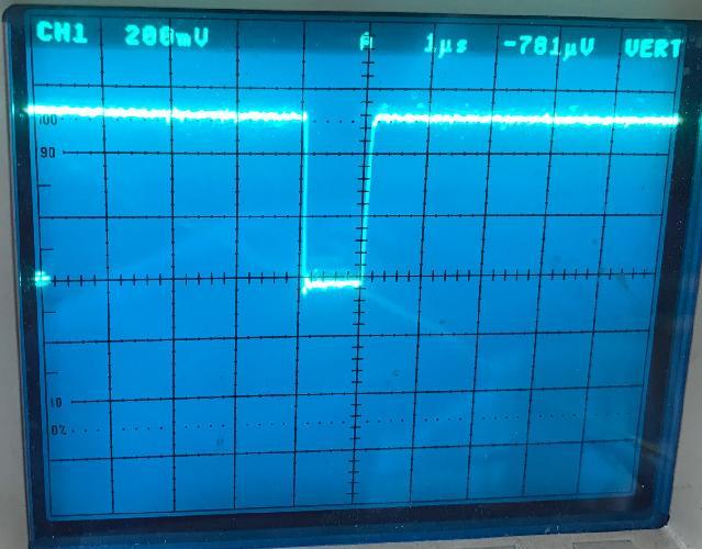
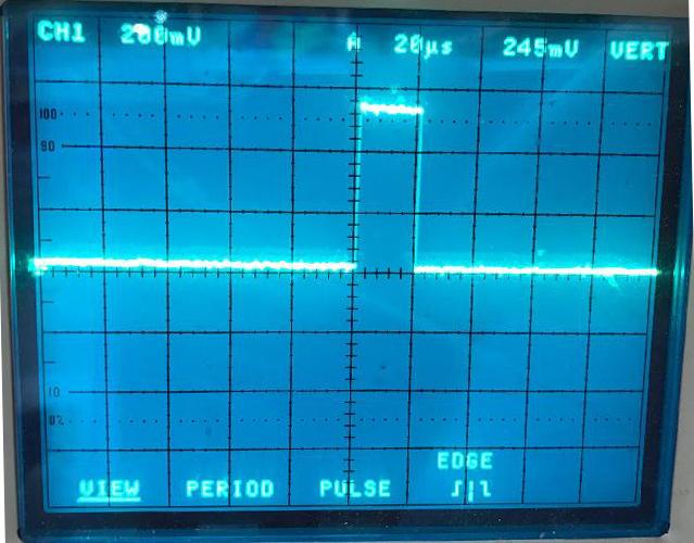
There's also a REDC signal at IC25 pin 15 and IC24 pin 15. This is the processor
reading the switch matrix. It should look like this:
Now let's look at the switch row path.
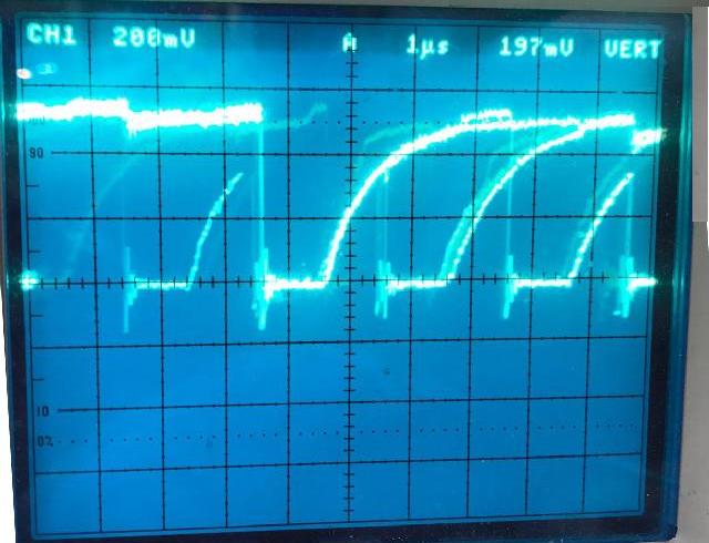
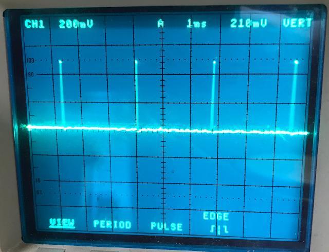
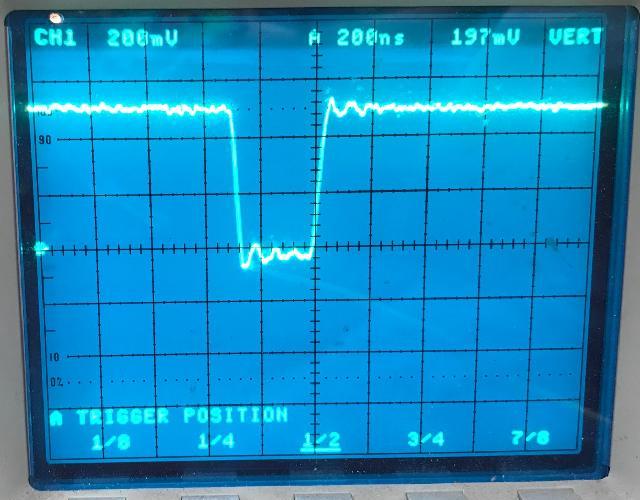
Switch matrix row1 at connector Cn11 pin2 and IC38 pin 1, with game in attract mode.
This is the same picture you should get at Cn11 pins 2-9 and Cn10 pin 6 (make sure you check
Cn10 pin 6, as it's a descrete transistor and not part of IC38. Also this is the same picture
you should see at IC38 pins 1,2,14,4,12,7,9.
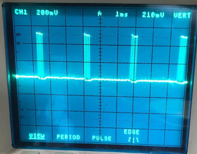
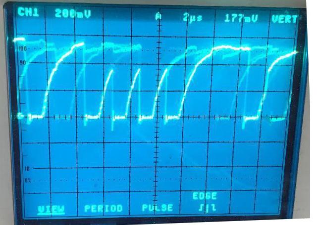
Here's going back one more step in the Switch matrix row1 to the input of IC38 pin 16
(the left side of ic38).
Also IC38 pins 3,13,6,11,8,10 should look the same. Note this is the chip that
fails most often in the switch matrix.
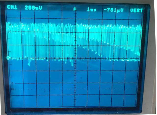
Back one more step, switch matrix row1 at IC41 pin 14. Also IC41 pins 3,2,15,1,6,7,4 should
also look the same:
Back one more step, Switch matrix row at IC41 pin 10 (A0). Note this should look
the same at IC41 pins 13,12 (A1,A2). Also same signal at IC33 pin 2,10,11.
Back one more step, switch matrix row IC33 pin 4 (DB0). The signal at IC33 pins 7,13,14 (DB1,DB2,DB3)
should look the same. Note is the same (time) sample rate as above.
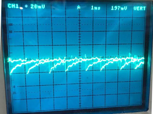
Again switch matrix row IC33 pin 4 (DB0) and IC33 pins 7,13,14 (DB1,DB2,DB3).
Note this a slower (time) sample rate to really show the wave form better.
If you want to back up to the 2650a processor IC9 pin 33 (DB0). All the data lines
(ic9 pin 33-26) should look about the same. Here's that picture:
There are also a WRTC instruction as the 2650a writes data to IC33.
This is IC33 pin 6. Notice the scope time is turned way down to show this:
And also at IC33 pin 1 there the RFSH signal. If that doesn't get strobed,
then the reset watchdog circuit reboots the CPU board:
Switch Matrix Charts.
The following are documents showing the Zaccaria switch matrix for
gen1 and gen2 games.
3h. Repair: Driver Board
The gen1 and gen2 driver boards are different. Technically the
ribbon cable interface makes them "conpatible", but in reality
they are no where near compatible. Here's some differences:
- Solenoid TIP transistor drivers: 21 for gen1, 24 for gen2.
- Lamp SCR drivers: 64 for gen1, 80 for gen2.
- Connectors: standard .100 and .156 for gen2, non-standard .100 and .156 for gen1.
Gen1 Driver Board Connectors.
The following shows where the driver board TIP and SCR connectors
attach on the playfield and/or backbox insert panel.
- CN13 pin 1: Q16
- CN13 pin 2: NC
- CN13 pin 3: Q17
- CN13 pin 4: Q15
- CN13 pin 5: Q6
- CN13 pin 6: Q5
- CN13 pin 7: Q18
- CN14 pin 1: Q14
- CN14 pin 2: Q7
- CN14 pin 3: Q4
- CN14 pin 4: Q19
- CN14 pin 5: Q13
- CN14 pin 6: Q8
- CN14 pin 7: Q3
- CN14 pin 8: Q20
- CN14 pin 9: Q12
- CN14 pin 10: Q9
- CN14 pin 11: Q2
- CN14 pin 12: Q21
- CN15 pin 1: Q11
- CN15 pin 2: Q10
- CN15 pin 3: SCR55
- CN15 pin 4: NC
- CN15 pin 5: SCR56
- CN15 pin 6: SCR61
- CN15 pin 7: SCR62
|
TIP Driver Transistors:
- Q1: CN18 pin 15
- Q2: CN14 pin 11
- Q3: CN14 pin 7
- Q4: CN14 pin 3
- Q5: CN13 pin 6
- Q6: CN13 pin 5
- Q7: CN14 pin 2
- Q8: CN14 pin 6
- Q9: CN14 pin 10
- Q10: CN15 pin 2
- Q11: CN15 pin 1
- Q12: CN14 pin 9
- Q13: CN14 pin 5
- Q14: CN14 pin 1
- Q15: CN13 pin 4
- Q16: CN13 pin 1
- Q17: CN13 pin 3
- Q18: CN13 pin 7
- Q19: CN14 pin 4
- Q20: CN14 pin 8
- Q21: CN14 pin 12
|
- CN16 pin 1: SCR57 (flipper relay)
- CN16 pin 2: SCR57
- CN16 pin 3: SCR60
- CN16 pin 4: SCR63
- CN16 pin 5: SCR64
- CN16 pin 6: NC
- CN16 pin 7: NC
- CN16 pin 8: NC
- CN16 pin 9: NC
- CN16 pin 10: SCR8
- CN16 pin 11: SCR25
- CN16 pin 12: SCR26
- CN16 pin 13: SCR43
- CN16 pin 14: SCR44
- CN16 pin 15: SCR7
- CN16 pin 16: SCR9
- CN16 pin 17: SCR24
- CN16 pin 18: SCR27
- CN17 pin 1: SCR45
- CN17 pin 2: SCR6
- CN17 pin 3: SCR10
- CN17 pin 4: SCR23
- CN17 pin 5: SCR28
- CN17 pin 6: SCR46
- CN17 pin 7: NC
- CN17 pin 8: NC
- CN17 pin 9: SCR11
- CN17 pin 10: SCR22
- CN17 pin 11: SCR29
- CN17 pin 12: SCR40
- CN17 pin 13: SCR47
- CN17 pin 14: SCR4
- CN17 pin 15: SCR12
- CN17 pin 16: SCR21
- CN17 pin 17: SCR39
- CN17 pin 18: SCR48
- CN18 pin 1: SCR38
- CN18 pin 2: SCR49
- CN18 pin 3: SCR31
- CN18 pin 4: SCR14
- CN18 pin 5: SCR19
- CN18 pin 6: SCR32
- CN18 pin 7: SCR37
- CN18 pin 8: SCR50
- CN18 pin 9: SCR15
- CN18 pin 10: NC
- CN18 pin 11: SCR18
- CN18 pin 12: SCR33
- CN18 pin 13: SCR36
- CN18 pin 14: SCR51
- CN18 pin 15: Q1 (TIP driver)
- CN18 pin 16: SCR34
- CN18 pin 17: SCR35
- CN18 pin 18: NC
- CN19 pin 1: SCR?
- CN19 pin 2: SCR?
- CN19 pin 3: SCR57
- CN19 pin 4: SCR62
- CN19 pin 5: SCR60
- CN19 pin 6: SCR63
- CN19 pin 7: SCR64
- CN19 pin 8: SCR61
- CN19 pin 9: SCR52*
- CN19 pin 10: SCR42*
- CN19 pin 11: SCR41*
- CN19 pin 12: NC
- CN19 pin 13: SCR51
- CN19 pin 14: SCR35
- CN19 pin 15: SCR33
- CN19 pin 16: SCR37
- CN19 pin 17: SCR59*
- CN19 pin 18: SCR30*
* Unique SCR connections, all others duplicates to other connectors.
- CN20 pin 1: SCR34
- CN20 pin 2: SCR6
- CN20 pin 3: SCR58*
- CN20 pin 4: SCR20*
- CN20 pin 5: SCR5*
- CN20 pin 6: SCR17*
- CN20 pin 7: SCR4
- CN20 pin 8: SCR18
- CN20 pin 9: SCR13*
- CN20 pin 10: SCR15
- CN20 pin 11: SCR16*
- CN20 pin 12: NC
- CN20 pin 13: SCR53*
- CN20 pin 14: NC
- CN20 pin 15: SCR3*
- CN20 pin 16: SCR2*
- CN20 pin 17: SCR1*
- CN20 pin 18: Q1 (TIP driver)
* Unique SCR connections, all others duplicates to other connectors.
3i. Repair: Sound board issues
On Space Shuttle, the schematics say the sound board uses a 8085 processor.
This is WRONG. It actually uses an 8035 processor (which is complete different
and not compatible with an 8085).
3j. Repair: Flippers
The flippers used on Zaccaria games are unique. But the good news is,
largely Gottlieb and Bally parts can be substituted in many cases.
We'll talk about that in this part of this document.
3k. Repair: Score Displays Gen2
Like most other manufacturers from the 1970s and 1980s, Zaccaria used high voltage gas discharge score display tubes.
There are three variations in the actual display boards:
- Soccer Kings, Pinball Champ (Early gen2 games): 8 digits using four 2-digit display glasses for each player,
allowing the game to show 8-digit scores.
- Farfalla, Devil Riders, Time Machine: 7-digit display glass for each player.
- Magic Castle and games after it: 8-digit display glass for each player.
All 2nd generation Zaccaria games use five score displays, one for each player plus one that
shows the high score to date, ball in play, and/or "game time bonus".
Internally, all of the games work with eight digit
scoring, with the 7-digit games using the rightmost digit (the 1s place) to show the
ten-millions digit when necessary. All three of these designs use a similar display board,
with a set of jumpers to configure the board, and a ribbon cable connection carrying
display data and the 170VDC power for the gas discharge tube.
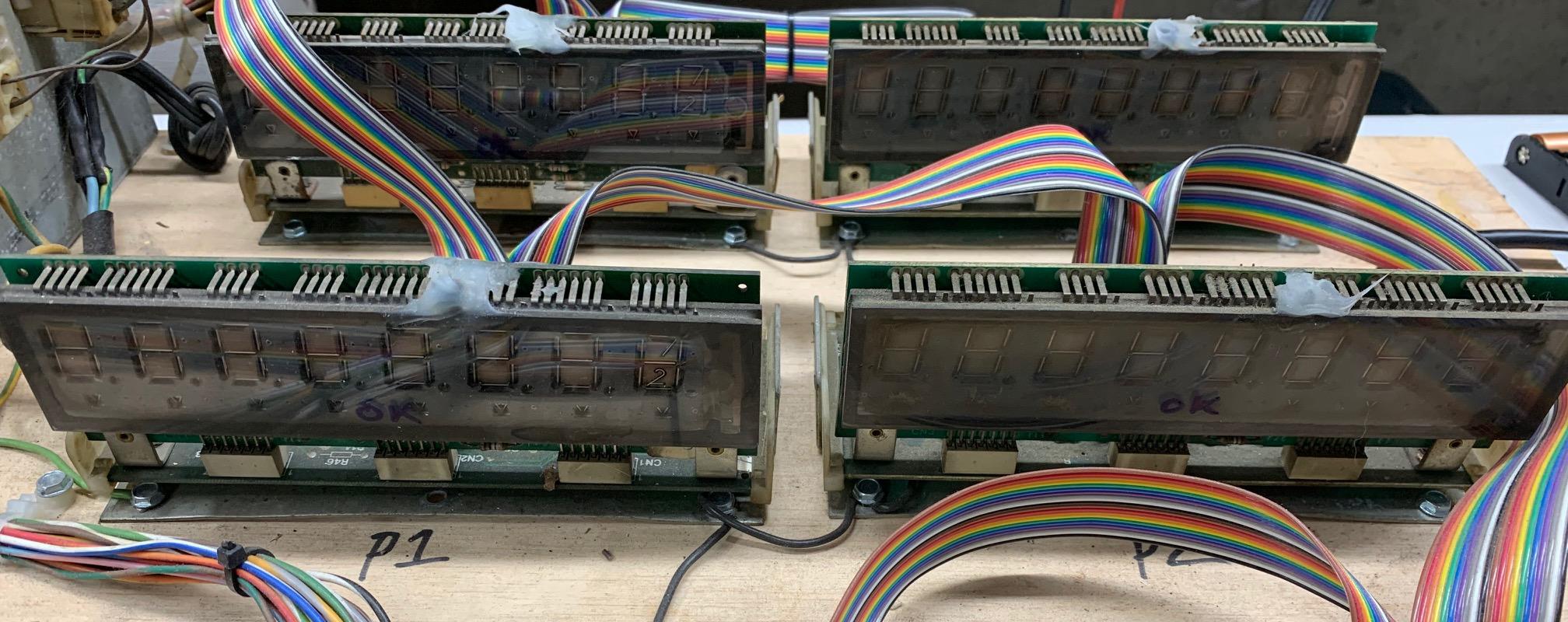
Soccer Kings, Pinball Champ style 8 digit display using 2-digit display glasses. Very problematic.
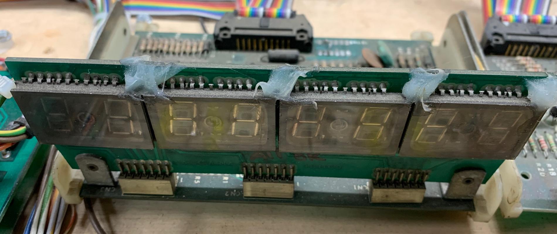
Farfalla, Devil Rider, Time Machine style 7 digit display glass. In the picture below one of the
display glass legs broke the solder joint to the control board, causing digit segment to not light.
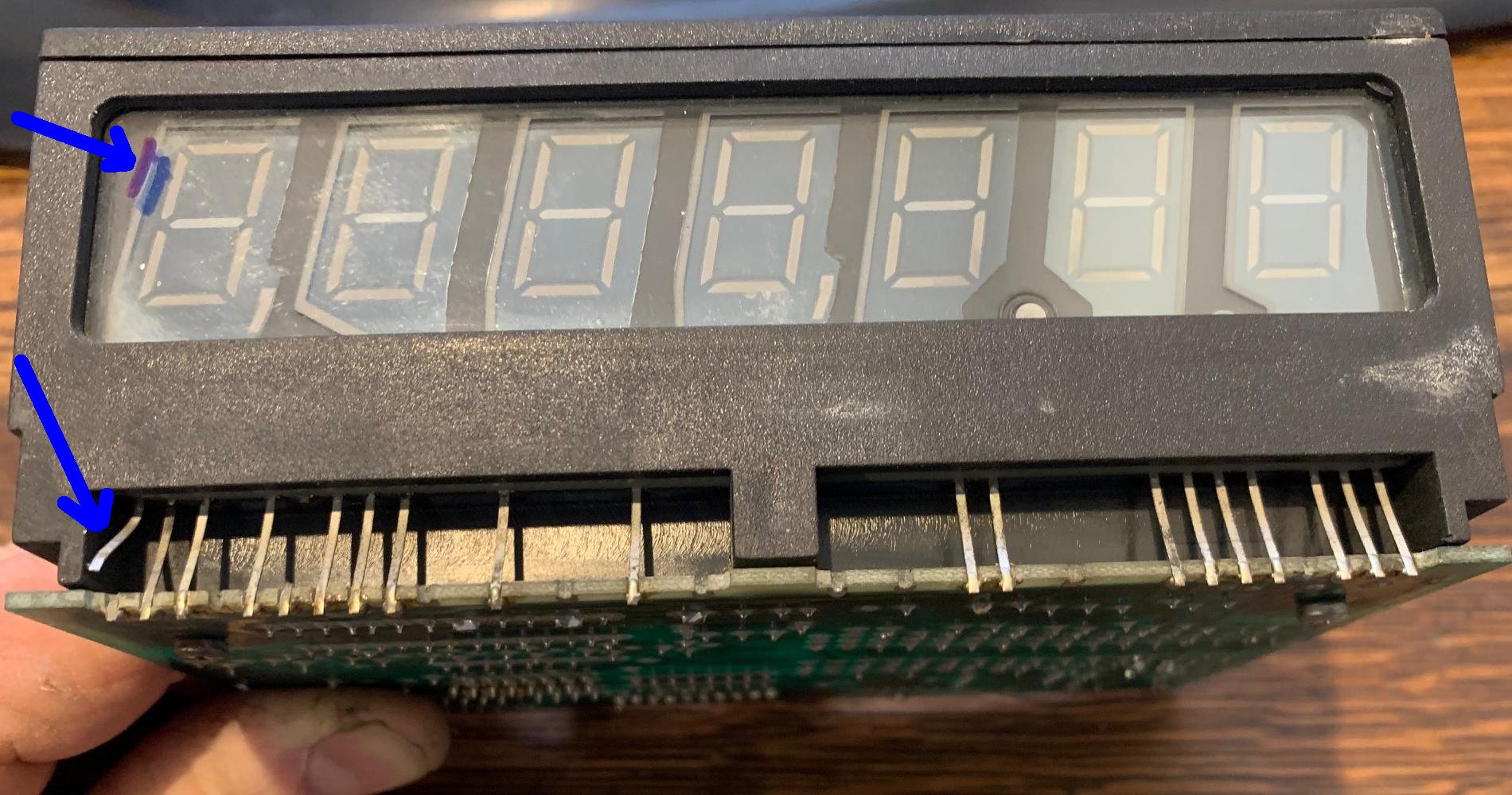
Magic Castle and later 8 digit display glass.
Electronically, all three display boards are similar. The 7-digit board is a variation from
the earlier 8-digit board, with a few unneeded components deleted.
The 8-digit and 2-digit display glasses have been out of production for many years and
are essentially unobtainable. Worse, the 2-digit display glasses are reported to have
a high failure rate due to their age and original manufacture quality.
The good news, if there is any on games using 8 digit scoring, is both varieties
(4x2-digit and 8 digit) are interchangeable. Well except that the mount bracket
is different between the two...
The 7-digit display glasses (Farfalla, Devil Rider, Time Machine) are standard
7-digit numeric displays, as used on Williams games like Jungle Lord. That's good
news as you can still buy these display tubes.
The good news is there are LED low voltage (5v) score displays now available
for all variants of Zaccaria gen2 games.
Common Gen2 Display Failure point (pre-Magic Castle) 4042 chip.
A common failure on the 4x2-digit and 7-digit displays is IC2 (4042 chip.)
This 4042BP Quad Clocked D, which crosses to NTE4042B. This is basically
the decoding chip for the display. So if digits are confused or even missing,
often this is the problem (it's kind of the Bally/Stern equivalent to their 4543 Cmos display chip.)
If you have at least one working display, compare IC2 on both boards with a DMM
set to diode setting (displays removed from game.) Any difference found, replace the chip.
Or just replace and socket the chip, as the 4042 is not expensive.
Note the single glass 8-digit displays (Magic Castle and later) do not use a 4042 chip.
Display Jumpers.
Unlike say Bally or Stern or Williams games, all the Zaccaria score displays variants must
be jumpered for the correct score display location. There are six jumpers...
Player1 gets jumper1 installed... Player4 gets jumper4 installed. For the
credits/ball display, jumper5 is installed. There is a jumper6 for games
that have an additional scoring position for other reasons (mostly relevant to gen1 games.)
With this in mind, if you have two score displays installed with jumper2, you will see the
second player score in two different score windows!
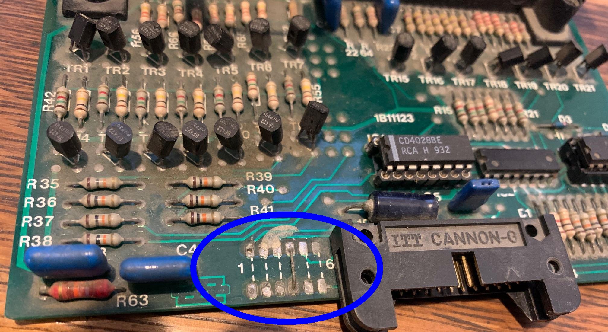
Score display board jumpers that signify which score will be displayed this that display glass.
This 7-digit Farfalla display is set for Player4.
Display Segment Failures.
The only common display failure on these displays is the BF422 SCR
that controls a digit *segments*. This SCR is no longer available, but can often
be found on ebay. The cross reference books say the ECG287 or NTE287 is a direct replacment,
but this is wrong. The specifications on the part match, but the pinout is incorrect.
Using an NTE/ECG287 in place of the BF422 on score display panels requires rough engineering.
You can use the NTE/ECG replacement, but you will have to cross two
legs to make it work. Install the NTE/ECG287 so that C goes to R5/R10, E goes to R16, and B goes to the
drive chip (HEF4511BP or FSS8301.)
Display Digit Failures.
On the 8-digit single score glass displays (Magic Castle and later) there are two obsolete chips.
Chip IC2 (UDN6510) can be replaced with a Dionics DI510B. But IC4 (ULN2823A) has no known replacement at this time.
Note on the 4x2-digit displays and 7-digit displays, these two chips were not used (instead they used individual transistors.)
* Go to the Pin Fix-It Index

