3a. When Things Don't Work: Fixing the MPU (LED flashes, etc.)
Six MPU Board Flashes.
A correctly working Gameplan MPU board will give six flashes of its diagnostic LED at power up.
This is similar to the 1977-1985 Bally/Stern LED diagnostic flashes. Similar but with
one exception... the Bally/Stern MPU diagnostic LED is "on" by default, by hardware. Therefore if the
software is not running, the Bally LED is "stuck on." GamePlan is different... the MPU
diagnostic LED must be turned on by software. Hence if the MPU board isn't running
the firmware (for whatever reason), the LED will be dark. It's someone omominous, because the
MPU board just looks dead, as the LED never flashes or shows any signs of life!
Just keep this in mind...
Also note these six GamePlan MPU flashes are largely consistent in timing.
That is, they happen with about the same time between each flash. This is
unlike the Bally MPU flashes, where there's different timing between flashes
(particularly the second and third MPU LED flashes.)
Powering the MPU board on the Bench.
Unfortunately the GamePlan MPU-2 board does not want to power on with a
computer power supply on the work bench like a 1977-1985 Bally or Stern MPU board will.
The best I could do was one flash of the GamePlan MPU-2
board's LED with a computer power supply connected to TP1, TP2 and TP7 (which makes
sense as the second LED flash is the zero cross check, which is missing since I don't
have 25 volts DC attached to J1 pin 3). If I connected
a 24 volt Radio Shack transformer going through a bridge rectifier to J1 pin 3,
I could get four MPU board LED flashes (do not use a filter capacitor as
this will mess up the zero crossing circuit which is powered by the 24 volts).
This I find strange too as no fifth LED flash means the U17 (8255 PIA) is bad,
which clearly isn't the case in my tests as the MPU board boots just fine
with the GamePlan power supply connected.
Here are the connections I was using, perhaps
you may have better luck (if you do please let me know). Note connector J1 is the
main MPU board connector at the lower right side of the MPU board. This applies
to MPU-1 and MPU-2.
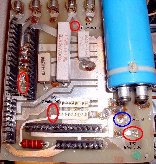
- TP1 = +5 volts DC (test point located lower right corner by J1).
- TP2 = +12 volts DC (test point located below red CPU switch at upper right).
- TP7 = Ground (test point located below DIP switches near TP2).
- J1 pin 3 = 24 volts DC (solenoid voltage).
- TP6 (located below U3, zero cross) = Should be about 4.9 volts DC. If not check for 24 volts DC at J1 pin 3.
- TP5 (located to the right of U11) = CLOCK Test Point. Should be about 2.1 volts.
- TP4 (located below U7) = RESET Test Point. Should be 5 volts.
Getting More LED Flashes on the Bench.
A trick J.Clause tells is to power up the GamePlan MPU board on the bench
with +5, +12 and ground (as described above) - You'll get the first LED
flash only. Now take an alligator jumper wire to the power supply's +12 volts
and just *touch* the MPU board's J1 pin 3 connector for a moment. Now the
other five LED flashes should go and the board should fully boot. Note if you power
up the MPU board with the +12 volts already connected to J1 pin 3, this will not work
(you will only get one LED flash). Note this technique takes some practice to make
it work, and it's not consistent. But it's worth trying if you're doing bench work.
But really the best way to test a GamePlan MPU is using GamePlan power supply.
Required MPU board Connectors.
The only MPU board connector needed to power on the MPU board is J1 (lower right).
This supplies the +5, 12 and 24 volts DC power to the board. Also if the
MPU board has a connector on J8 (lower left corner), that will need to be
connected too (this supplies -5 volts for the TMS2716 EPROMs at U12, U13 and U26),
if the board is using TMS2716 EPROMs (otherwise it's not needed.)
For diagnosing MPU board problems, it is suggested that all other connectors be removed
except for the lower right power connector.
If desired, the MPU board top card-edge connector can also be left in place
if you want the score displays to be used.
Reset Line (First Step in a Non-Booting MPU board).
Before the CPU chip will start to run, the reset line on the Z-80 CPU chip U11 pin 26 must
be high (5 volts). The reset circuit of the MPU board controls the reset; Upon
power-on, U11 pin 26 is held low (0 volts) for a short period of time (50 milliseconds
or so). This allows the 5 volt power supply to stablize. Then the reset circuit
makes z80 U11 pin 26 go to 5 volts. This is done using four transistor QA,QB,QC (2N3904)
and QD (2N4403), a 1N4738 8.2 volt zener diode, and some resistors and caps.
Unfortunately the reset circuit is right below the battery, so battery corrosion
often ruins this circuit. If the reset circuit of the MPU board is not working,
the MPU will *not* start to boot.
With the power to the MPU board on, use a DMM and check z80 U11 pin 26. It should
be 4.5 to 5.1 volts DC. With the power off and the DMM on and connected
to U11 pin 26, turn the power on to the MPU board. The DMM should show 0 volts
for just a brief moment, and then jump up to 4.7 to 5.1 volts. if it does
this, the reset circuit is working. If U11 pin 26 stays at less than 4 volts,
the reset circuit is faulty. Start by replacing the four transistor QA,QB,QC (2N3904)
and QD (2N4403). Also it's a good idea to replace the 1N4738 8.2 volt zener diode
(the Gameplan parts list calls or a 1N959B diode, but use a 1N4738 instead).
Verifying the Reset Section is Bad.
With the MPU on the bench, power it up.
Check z80 u11 pin 26 for 4.5 to 5.1 volts. If this pin is low, it
may be because the reset section is not working correctly.
An easy way to verify the reset section as bad is to jump
U11 pin 25 to U11 pin 26. This bypasses the reset section, putting
5 volt right on U11 pin 26. If the board starts its LED flashes
after doing this, you know the reset section is bad.
Constant Resets - LED Flashing Constantly or U11 Pin 26 high/low/high/low.
Gameplan uses a watchdog style timer concept on their board.
It's sort of like Williams blanking system on system3-7 CPU boards
(but the similarities end there.) It's easy to see this problem...
usually the LED will continually flash over and over, non-stop,
but not always! Sometimes this will happen if you have your DMM
on U11 pin26 and it keeps going from 4 volts to 0 volts over and over.
In either case, the MPU is reseting itself.
The big question is, what causes this problem?
It is difficult to determine the problem... is the MPU is
not running correctly, so the watchdog is resetting the board?
Or is there something wrong in the watchdog circuit?
The first course of action is to replace all the socketed chips
with known good examples. This is u11 (z80), u10 (z80ctc), u17 (8255 PIA),
ROMs (u26/u13/u12), u8 (6810 RAM), u7/u6 (6551 RAM). I would consider
this the easy part, as all those components are socketed from the factory.
If the continual reset still exists after this, then things get difficult...
Next other components can be suspect, in this order, u14 (74ls154), u1 (74ls123), u2 (LM339), u3 (74ls04)
and u5 (74ls32) as these are all part of the watchdog/reset circuit.
If one of these components is bad, it could be responsible for the constant resets.
The u14 chip (74ls154) is probably most suspect for this problem.
You can check u14 with a DMM set to diode function, and it should show
.4v to .6v on all pins except for pins 18/19 (0v) and pin 24 (.2v to .3v.)
A trick to get around the reset/watchdog circuit is to short u11 pin25 and u11 pin26 together.
This gets around the reset circuit... but if u11 pin26 is continually going high/low/high/low,
this trick may not work.
If the shorting u11 pin25 and pin26 together does work and the LED does it's six flashes,
there is definitely a problem in the reset circuit. Easy enough, that circuit is not too difficult
to repair. Also the u17 PIA 8255 or u14 (74ls154) could be the issue.
If the shorting u11 pin25 and pin26 together does work and the LED does less than six flashes,
check the LED flash codes below, and replace/repair the identified component.
If the shorting u11 pin25 and pin26 together causes the LED to lock on,
there's a good chance that one (or two) of the 6551 RAMs at u6/u7 is probably bad.
Other things to think about if the continual resets are still happening...
The output of u14 pin11 (74ls154) sends a periodic signal to chip
u1 (74ls123.) Now another timing signal comes from
the u2 (LM339) and is combined and checked. If the signal from u14 (74ls154) does not get
to u1 (74ls123) in time, the signal from u2 (LM339) goes through and sets the 5volts low to the
MPU z80 u11 pin26 reset pin. Also the timing of the signals for u1 (74ls123) and u2 (LM339) is set by the
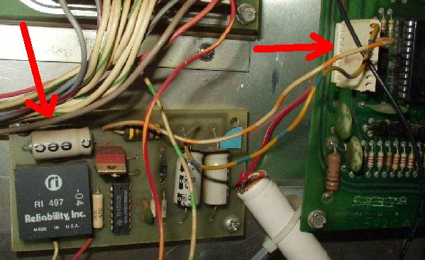
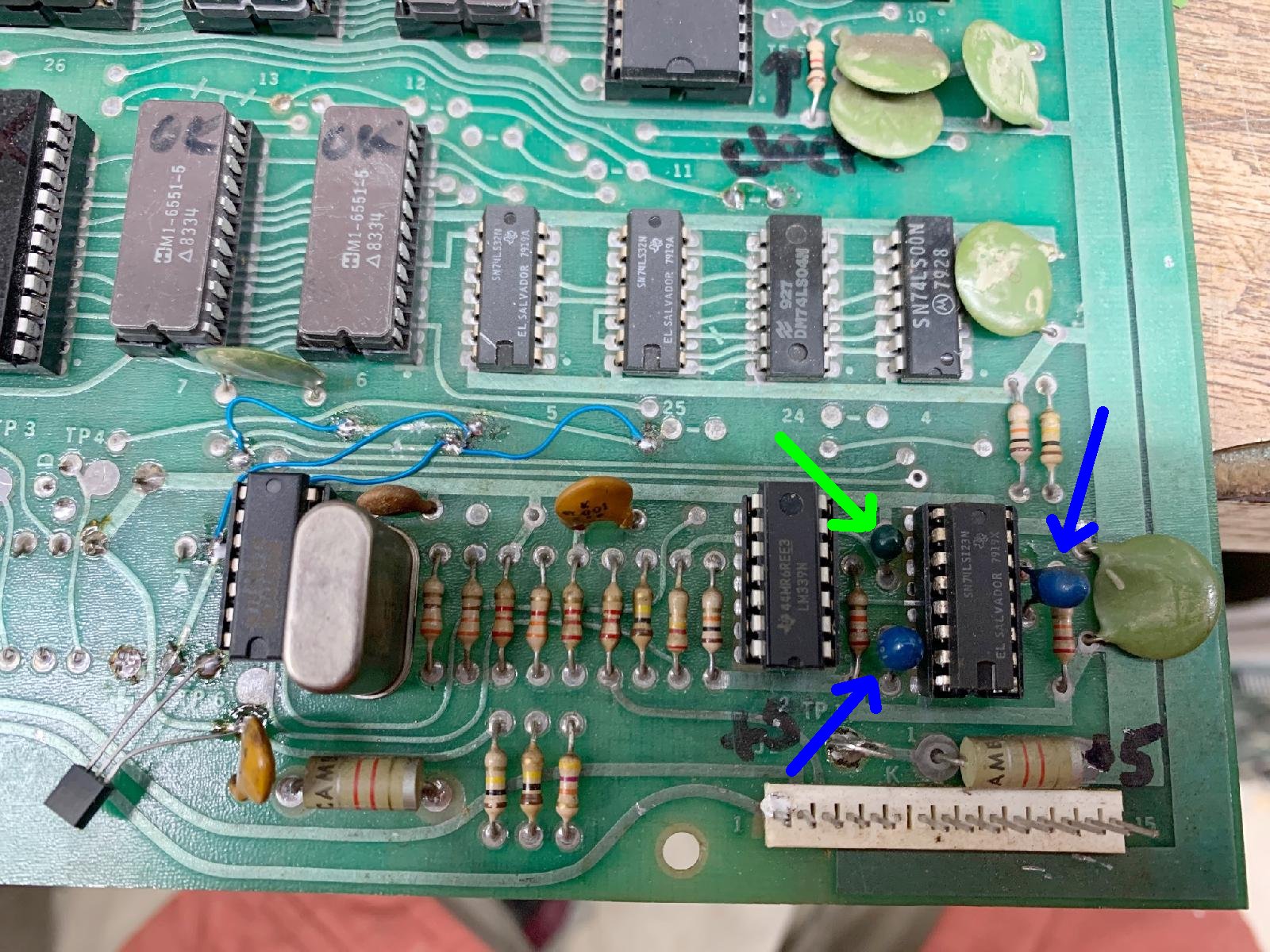
three tantalum caps (usually blue) around these components. If you look at the
schematics, you'll see that all three caps are 1mfd. But there is a chance that the board
has two 10mfd caps and one 1mfd cap.
Apparently the GamePlan engineers found that all 1mfd caps
was prone to unintentional resets. Hence they decided
to use two 10mfd caps, which put more tolerance into the watchdog circuit.
The 10mfd caps are across u1 pins6/7 (pin7 is +) and u1 pins14/15 (pin15 is +).
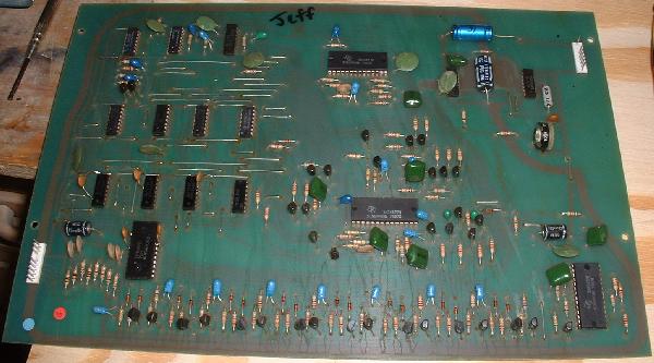
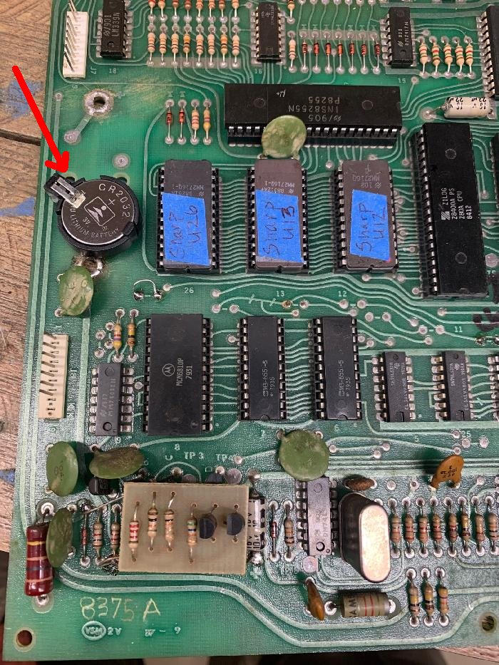
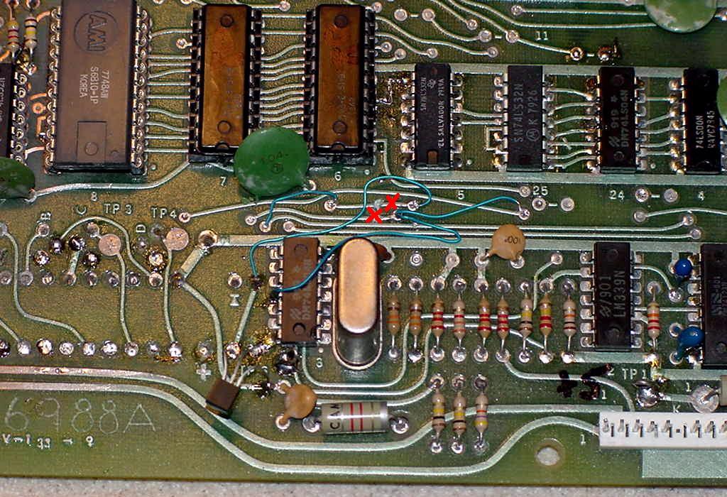
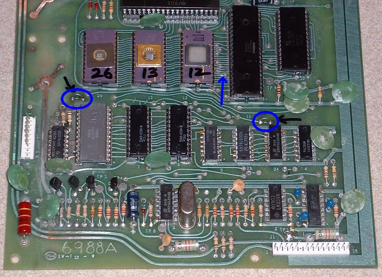
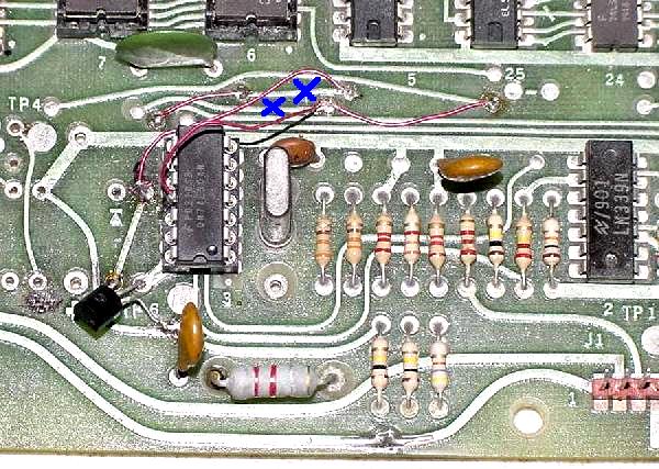
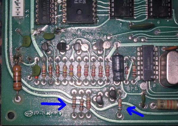
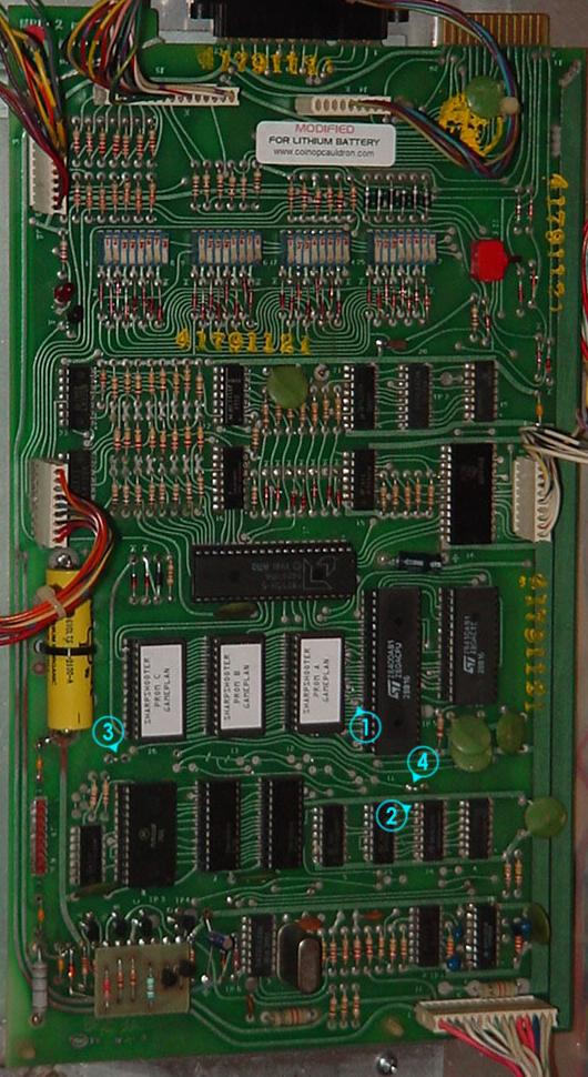
The three caps which are part of the watchdog.
The two blue caps with the blue arrows are the 10mfd variety.
The one green cap with the green arrow is 1mfd.
If the MPU is still doing it's continual resets, the problem can only
be a problem with u1 (74ls123) or the three tantalum caps. You can test U1 using a DMM
set to diode function and should see .4v to .6v on all pins except pins3/11/16 (.3v) and pins6/9/14 (0v).
If u1 (74ls123) checks out, that leaves the caps, and they should be replaced.
After u1 (74ls123), the signal goes to u5 (74ls32) where it is combined
with a signal from u3 (74ls04.) The signal at u3 is controlled by the 10mfd electrolytic cap
at the bottom of the board (if using a Dallas reset chip this cap has been removed,
as are the A/B/C/D transistors mentioned below.)
It is rare that this 10mfd electrolytic cap goes bad, but it's cheap if you want to replace it.
Also check u3 (74ls04) and u5 (74ls32) with a DMM set to diode function (.4v to .6v)
After this, there are four transistors labeled A/B/C/D on the board with A/B/C being 2n3904 and D is a 2n4403.
If the MPU-2 board has a 12 volt reset daughterboard, there will
be two additional 2n3904 transistors that can be checked.
Another possible problem can be the connection between the u17 PIA and u14 (74ls154) and u1 (74ls123.)
So it's not a bad idea to check these connections:
- u17 pin37 to u14 pin20
- u17 pin38 to u14 pin21
- u17 pin39 to u14 pin22
- u17 pin40 to u14 pin23
- u14 pin11 to u1 pin10
Last Words on the Watch-dog Timer (Continually Flashing LED.)
Thanks to Bob Russo. We covered this above, but here's another take on it.
If the LED flashes continuously, the watch-dog timer (WDT) isn't getting reset.
This makes diagnosing further problems with the board very difficult, since the
processor resets about 5 times a second.
In general, a watch-dog timer consists of some hardware components that
continuously tries to reset the processor. If the processor and some
related hardware is working properly, a signal will periodically be sent
to the watch-dog circuit, preventing the reset from occurring.
On the Gameplan CPU board, the watchdog works like this.
U2 (LM339) operates as an oscillator running at about 5 Hertz.
The output of U2 pin13 (LM339) is fed into one of the one-shots on U1 pin1 (74ls123.)
If the U1 pin2 is high, the U2 signal resets the processor.
The resistor and cap on the U1 one-shot determine the reset pulse width.
To prevent the reset from occurring, 74ls123 U1 pin12 has to be kept low.
This is done by pulsing pin10 faster then the pulse width on one-shot,
set by a different resistor and cap. On any particular Gameplan board, it's about 70ms.
This signal comes from U14 pin11. Problems with the processor,
U14 (74ls154), U17 (PIA 8255), chip selection circuitry, A0 and A1 data bus, and probably other things,
can keep this signal from getting back to the LM339 at U1.
I find it best to stop the resets from occurring while troubleshooting the WDT.
If the LM339 U2 chip is socketed, pull out U2 pin13. Or if everything is soldered in, you can run
a jumper from 74ls04 U3 pin12 to 74ls123 U1 pin10 (be sure you're getting a square wave at 60 Hertz
rate from LM339 U3 pin12). Either of these will stop the continuous resets and let you
troubleshoot the board. In this state, you can get the board to give up to 6 flashes.
Until you can get it to run with the WDT circuitry set normally, the board can't
properly work in your machine since anything attached to 74ls154 U14 won't work properly.
OK *Really* the Last Word on Watch-do Timer (Continually Flashing LED.)
Another thing to consider is if the software is running correctly on your MPU board.
If it is not, the reset line will continually go high/low/high/low. What I'm trying to
say is if you have the MPU board jumpered incorrectly for the ROMs you are using,
you will get continually resets. Also if a line is missing going to the U8 6810 RAM or
the U6/U7 RAM chips, same problem. So keep that in mind too.
Additional Daughter Reset Board.
Some Gameplan MPU boards (specifically Rev.1b) have a small two transistor circuit board
hovering above the reset circuit. Its purpose is to hold the processor in reset if
the 12 volt power supply isn't present. That's all it does! And with MPU board Rev.2 this
daughter board was incorporated in the MPU board (so Rev.2 has two additional transistors
and four additional resistors in the reset section.)
Schematic Valves versus Actual Valves.
It appears that GamePlan was pretty bad about updating their
schematics. And they would often make changes to capacitors and
resistors, especially in the reset section. Therefore if you remove
a component from your board, yet the schematic value is different,
your replacement component should reflect the value removed from the board.
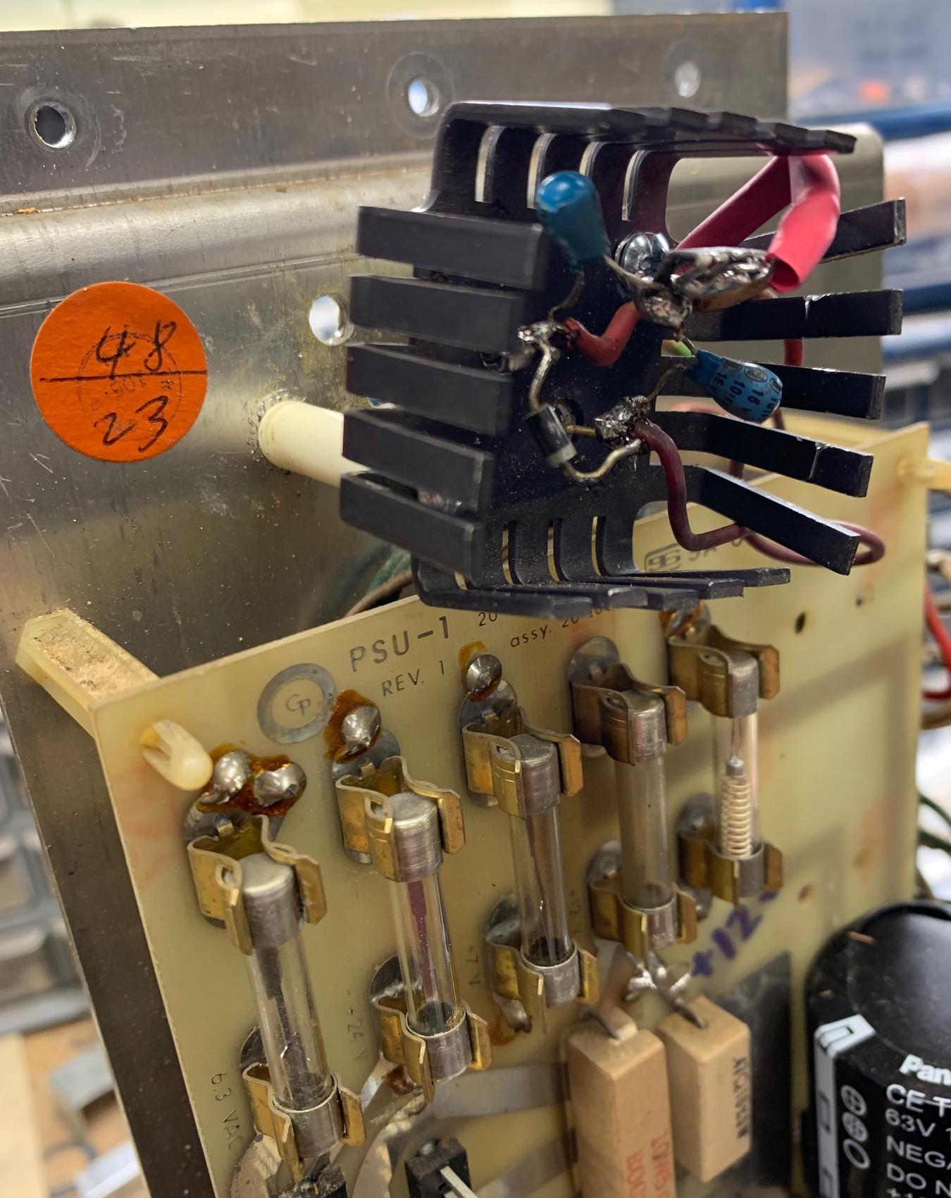
MPU Reset/Clock Circuit Parts List.
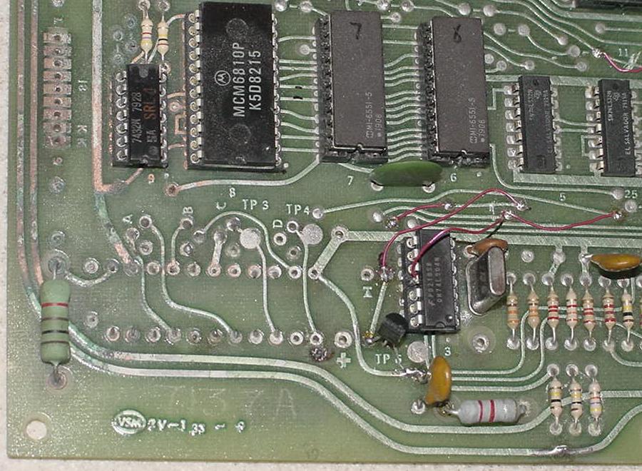
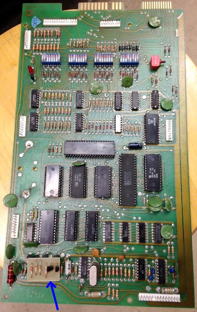
Here's the parts layout for the reset section that are often damaged by battery
corrosion for the MPU-2 board (as used on all non-cocktail pinballs).
Parts are listed by row and in order from left to right on the MPU-2 board's reset
section in the lower left corner of the MPU-2 board, starting just to the
left of connector J8. Note the paragraph above regarding schematic values
versus actual component values in the board...
MPU-1 Reset Parts (by row):
- 4.7k ohm 1/4 watt resistor
- 100k ohm 1/4 watt resistor
- 74LS32 or 74C32 chip (U9) - should be 74c32 as that is a low power version.
This is important to keep good battery life. An 74hc32 is also a good choice.
- 6810 RAM chip (U8)
- 6551 CMOS chip (U7)
- 6551 CMOS chip (U6)
- 74LS32 chip (U5)
- .1 mfd 25 volt ceramic cap (below U9 74LS32 chip).
- .1 mfd 25 volt ceramic cap.
- 2N3904 transistor (QA)
- 2N3904 transistor (QB)
- 2N3904 transistor (QC)
- 2N4403 transistor (QD)
- .1 mfd 25 volt ceramic cap
- 1N959B or 1N4738 zener diode
- 1k ohm 1/4 watt resistor
- 8.2k ohm 1/4 watt resistor
- 8.2k ohm 1/4 watt resistor
- 120k ohm 1/4 watt resistor
- 47k ohm 1/4 watt resistor
- 47k ohm 1/4 watt resistor
- 22k ohm 1/4 watt resistor
- 22k ohm 1/4 watt resistor
- 22k ohm 1/4 watt resistor
- 22k ohm 1/4 watt resistor
- 22mfd 16 volt electrolytic capacitor
- 1N4148 diode
- 10k ohm 1/4 watt resistor
- 74LS04 chip
- 2.4576 mHz crystal
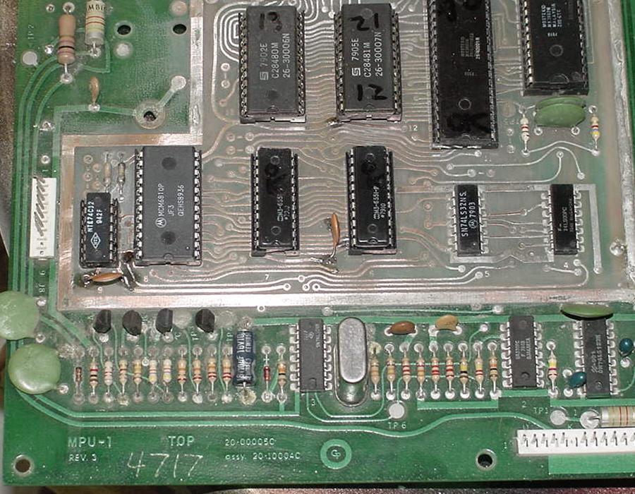
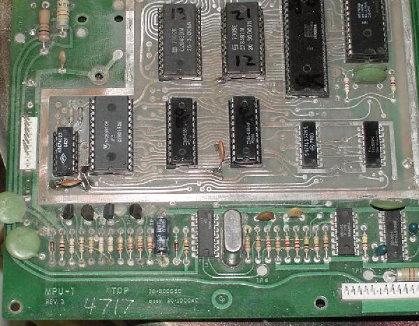
The lower left MPU-1 board's reset/clock circuits, often damaged by battery leakage.
MPU-2 Reset Parts (by row):
- 4.7k ohm 1/4 watt resistor
- 100k ohm 1/4 watt resistor
- 74LS32 or 74C32 chip (U9) - should be 74c32 as that is a low power version.
This is important to keep good battery life. An 74hc32 is also a good choice.
- 6810 RAM chip (U8)
- 6551 CMOS chip (U7)
- 6551 CMOS chip (U6)
- 74LS32 chip (U5)
- .1 mfd 25 volt ceramic cap (below U9 74LS32 chip).
- .1 mfd 25 volt ceramic cap (below and between U6/U7 6551 chips).
- .1 mfd 25 volt ceramic cap.
- 2N3904 transistor (QA)
- 2N3904 transistor (QB)
- 2N3904 transistor (QC)
- 2N4403 transistor (QD)
- 100 ohm 1 watt resistor
- .1 mfd 25 volt ceramic cap
- 1N959B or 1N4738 zener diode
- 1k ohm 1/4 watt resistor
- 8.2k ohm 1/4 watt resistor
- 8.2k ohm 1/4 watt resistor
- 120k ohm 1/4 watt resistor
- 47k ohm 1/4 watt resistor
- 47k ohm 1/4 watt resistor
- 22k ohm 1/4 watt resistor
- 22k ohm 1/4 watt resistor
- 22k ohm 1/4 watt resistor
- 22k ohm 1/4 watt resistor
- 22mfd 16 volt electrolytic capacitor
- 1N4148 diode
- 10k ohm 1/4 watt resistor
- 74LS04 chip
- 2.4576 mHz crystal
- small ceramic cap above crystal on some boards.
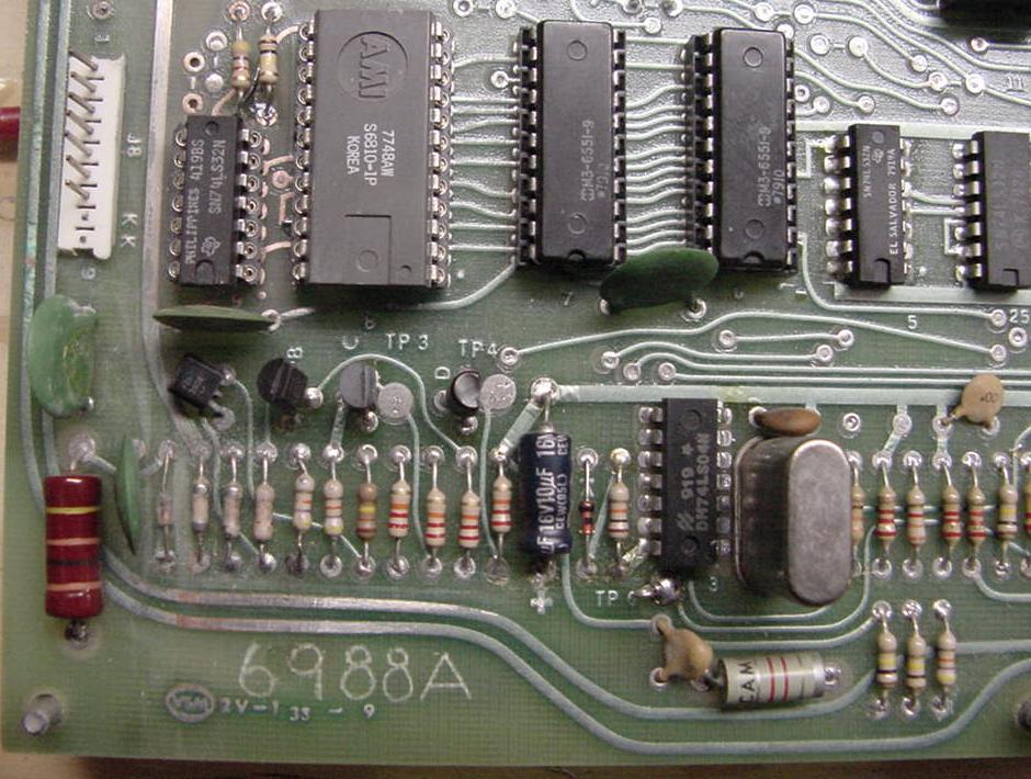
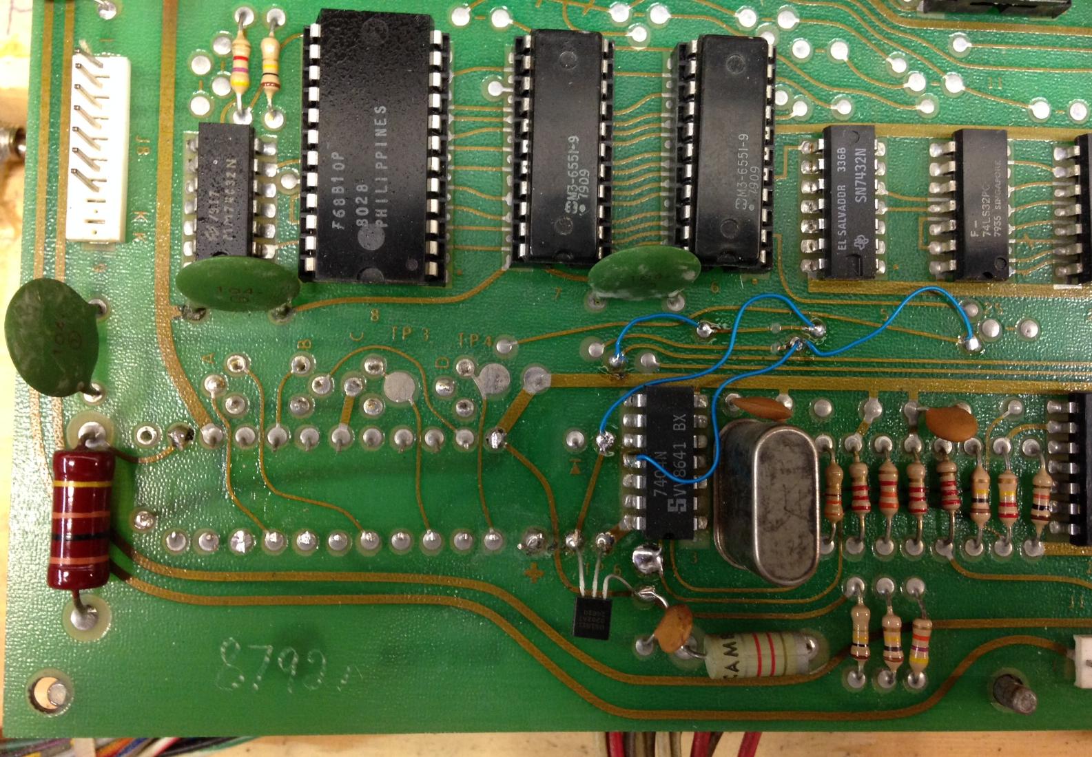
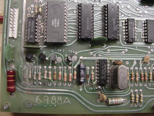
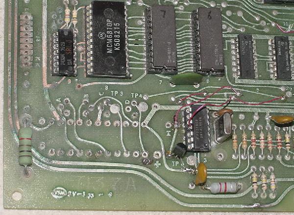
The lower left MPU-2 board's reset/clock circuits, often damaged by battery leakage.
Replacing the MPU-2 Reset Section with a Dallas DS1811 or MicroChip MCP101.
If there is too much corrosion or you just don't want to mess with replacing
a gang of resistors, the whole reset section can be replaced with a single
Dallas DS1811-10 or MCP101-450 reset chip. I *highly* suggest this modification!
The Dallas reset chip looks like 3-legged
transistors, but it's really a "supervisor reset chip". I can't recommend
this modification enough!! It takes a really crappy and weird GamePlan reset circuit
and makes it tight and concise. Less crap to go wrong! Here
are the instructions for installing a Dallas in a MPU-2 board:
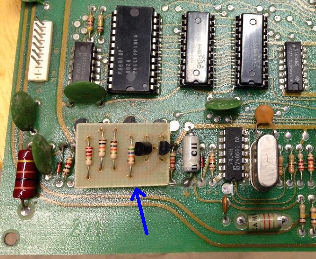
The entire MPU-2 reset section replaced with a MCP101-450.
- If you have a Rev.1b MPU board, cut off the 12v reset board in the reset section.
It is attached with four wire leads.
- Remove the lower left row of diodes, resistors and caps all the
way to the U3 (74LS04) chip (see picture). These parts include
(from left to right):
- .1 mfd 25 volt ceramic cap,
- 1N959B or 1N4738 zener diode,
- 1k ohm 1/4 watt resistor,
- 8.2k ohm 1/4 watt resistor,
- 8.2k ohm 1/4 watt resistor,
- 120k ohm 1/4 watt resistor,
- 47k ohm 1/4 watt resistor,
- 47k ohm 1/4 watt resistor,
- 22k ohm 1/4 watt resistor,
- 22k ohm 1/4 watt resistor,
- 22k ohm 1/4 watt resistor,
- 22k ohm 1/4 watt resistor,
- 22mfd 16 volt electrolytic capacitor,
- 1N4148 diode,
- 10k ohm 1/4 watt resistor
- Remove the QA, QB, QC, QD reset transistors just above the row
of resistors and caps just removed. And if you have a Rev.2 MPU
board, removed two more transistors and four resistors (which is the
Rev.1b daughter board components, incorporated directly into the MPU board.)
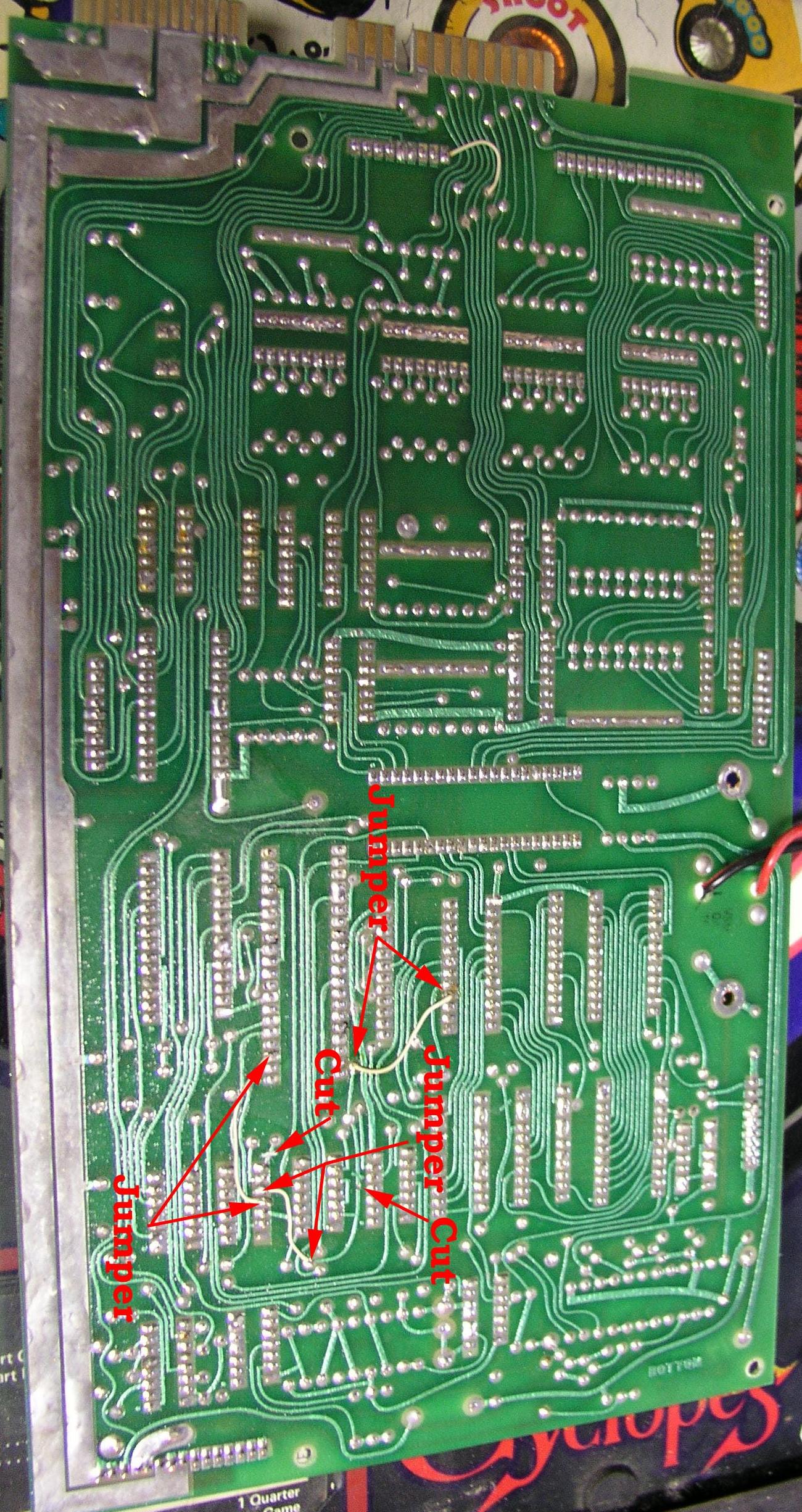
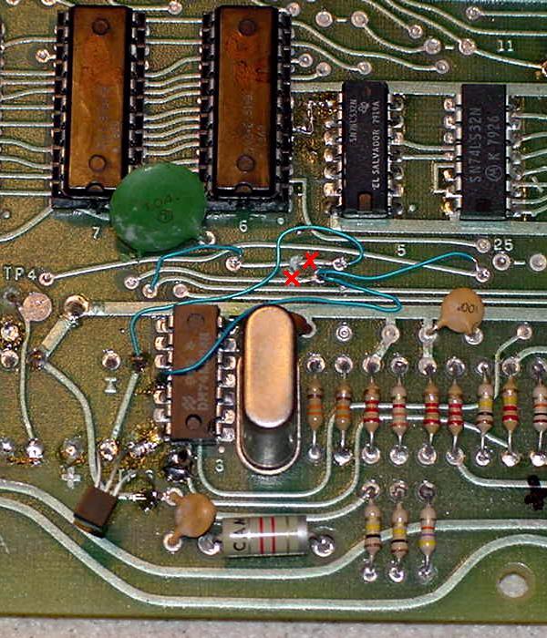
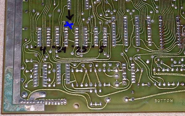
- On the component side above chip U3 (74LS04), there are six traces
running left to right. Cut the 4th and 5th trace (see picture) as counted
starting from the the top edge of the U3 chip and moving up. (Note
the first thick trace above U3 is ground, and this is "trace#1".)
- Connect a jumper from U3 pin 11 to the right side of the 4th
trace cut in the step above.
- Continue the above jumper so it connects to the 6th trace (lower hole of the "25"
labeled solder pads).
- Connect a jumper from the trace on the left side of U3 to the
right side cut of the 5th trace.
- Connect a jumper from the 3rd trace to the left side cut of the 5th trace.
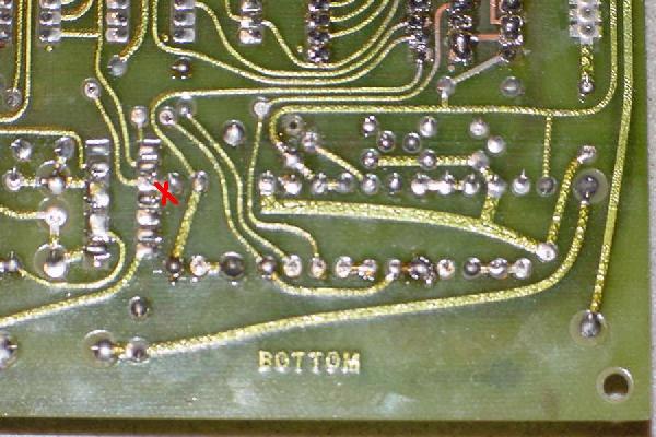
- On the SOLDER side of the board cut the trace going to U3 pin 11.
- Install a Dallas DS1811-10 or MCP101-450 to the bottom left of the U3 chip
(see picture). The middle leg connects to U3 pin 14, the right leg connects
to the top leg of the ceramic cap just below U3. The left leg connects
to the trace jumpered to the right side cut of the 5th trace.
- If installing a Dallas DS1811-10, the FLAT side of the DS1811 faces towards U3.
If installing a MCP101-450 the FLAT side of the MCP101 faces away from U3.
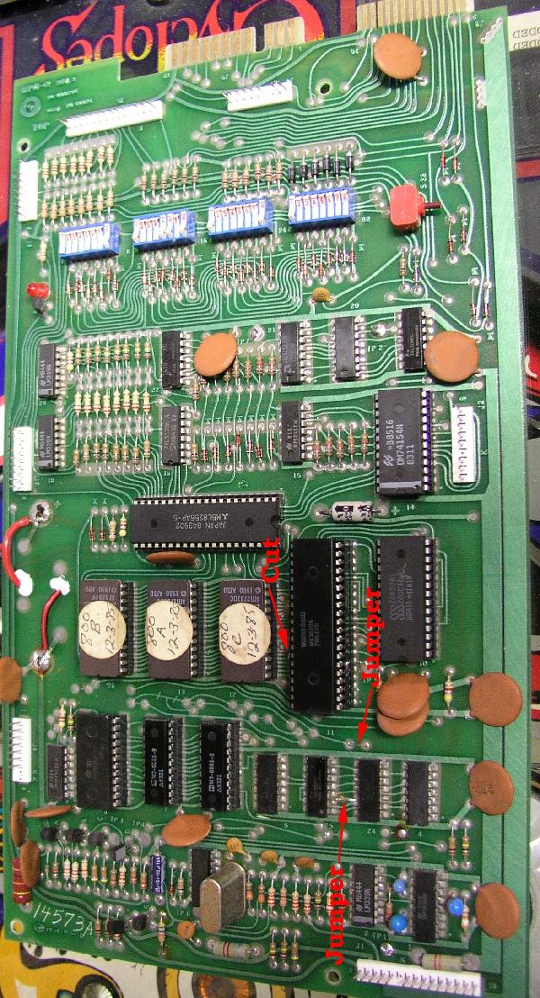
The cuts and jumps required for the reset chip. Installing a Dallas DS1811 or
Microchip MCP101 is exactly the same, but the orientation of the DS1811 is opposite
the MCP101 (the MCP101 has it's flat side *away* from U3, the Dallas 1811 has its
flat side *towards* U3). The MCP101 is shown here.
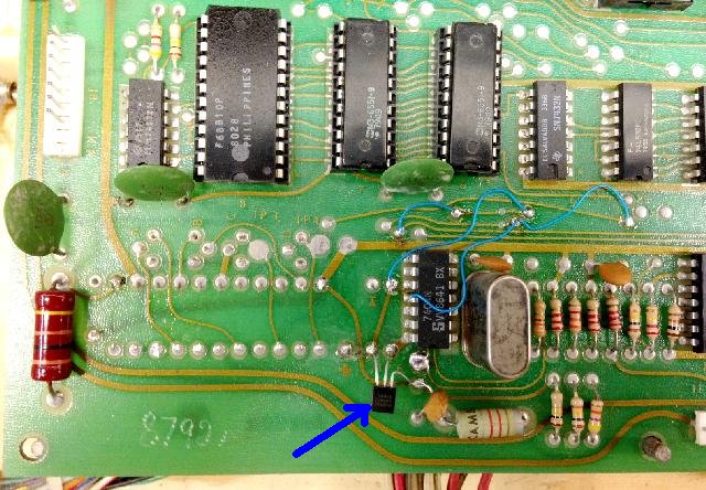
Another board modified to use a Dallas 1811. Notice the cuts and jumps.
Solder side: the trace going to U3 pin 11 is cut for the Dallas 1811 to work.
Adding a Reset LED to the MPU board.
I find it useful to add a reset LED to the MPU board. It tells me,
at a glance, if the reset circuit is working properely.
If you are having problems with constant watchdog/reset issue, this is
a great mod. A really *easy* modification if you have installed a Dallas reset chip installed,
but still easy if you're using the stock GamePlan reset too...
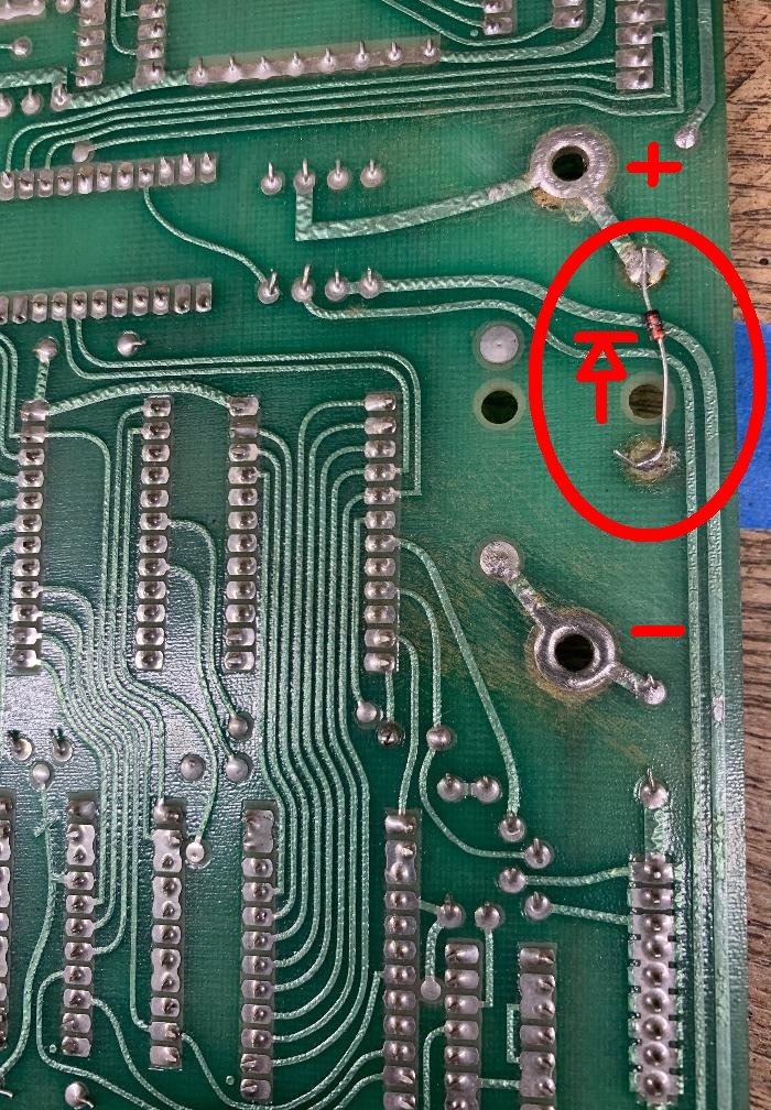
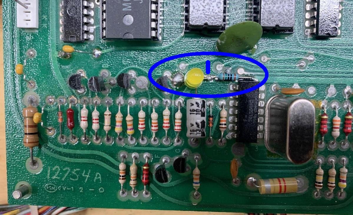
Basically what you are doing is adding an LED (non-flat side) to TP4 (the Reset test point),
and the (flat side) LED lead to a 150 ohm resistor that goes to ground.
If the reset is "high" (as it should be), the LED will be on.
Since TP4 should be about 5 volts, you need a 150 ohm resistor
to go with the LED. In the case of a Dallas reset chip, I install
the LED in the top two holes of the removed "D" transistor (with the flat
side of the LED to the left down.) And then mount a 150 ohm resistor between the
fifth unused top resistor hole from the right, to ground (which is the right most unused solder point.)
On stock reset circuit mounts, installeding the reset LED is not as clean looking.
See the pictures below....
An installed LED for the Reset line with a Dallas reset chip. This LED should be on
if the reset is high.
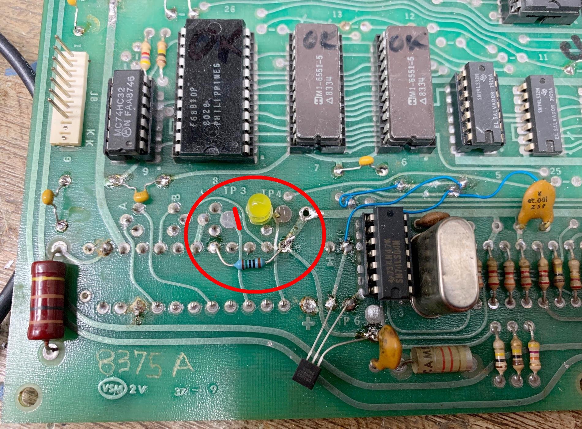
An installed LED for the Reset line on a stock Rev.2 MPU board. This LED should be on
if the reset is high. Non-flat side of the LED is connected to TP4, and the flat side
of the LED goes to a 150 ohm resistor which connects to ground.
Newer Reset Section for MPU-2 board Rev.1b and Rev.2
Somewhere in the era of Sharpshooter, Gameplan changed the reset
section on their boards. Intially they added a reset daughter board that hovers
above the reset section (aka Rev.1b MPU board.) But with Rev.2 GamePlan added the four resistors and
two transistors from the hovering daughter board directly into the MPU board itself.
This daughter board or Rev.2 modification added reset capabilities if 12volts was missing.
Newer MPU-2 reset section with four extra resistors and two extra transistors
added below and left of the electrolytic capacitor.
Reset Daughter board.
Also in the Sharpshooter era, the MPU-2 reset section was changed
by adding a small reset daughter board (aka Rev.1b MPU board.)
This board added some resistors and two transistors.
This resets the game if 12 volts is not present.
Newer MPU-2 with added reset board. (Pic by Kupla.)
Frankly this reset board was just a bandaid to a nagging problem.
Again the best solution is to just cut the board out, along with
the other reset parts (as shown above), and install a Dallas DS1811
reset chip. Below are pictures of this newer Gameplan reset daughter
board, it's removal, and the addition of the Dallas DS1811 chip
(as described above.) The process for using the Dallas reset chip
is no different on these board. The only added step is removal
of the Gameplan-added reset daughter board.
Newer MPU-2 board with the added reset daughter board.
Close up of the reset daugther board.
Removal of the reset daughter board and installation of a Dallas Ds1811.
Clock Signals (Second Step in a non-working MPU board).
Now that the reset circuit is working, the next thing to look at is
the clock circuit. Again if this circuit is not working, the MPU
will never start to boot.
The main clock circuit components are the 2.4576 mHz crystal
and the 74LS04 chip at U3. One way to test the clock is to
check TP5, which is located to the right of the CPU chip U11.
With a DMM TP5 should measure about 2.1 volts DC. Another good
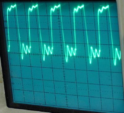
way to check the clock circuit is with an oscilloscope at TP5, U3 pin 1,
and U3 pin 4. Below are pictures of what should be seen on the scope.
If the below pictures are not seen or TP5 does not show 2.1 volts
on a DMM, try replacing U3 (74LS04).
Clock at U3 pin 1 (Time division and delay both set to .2 on a Tek 465 scope).
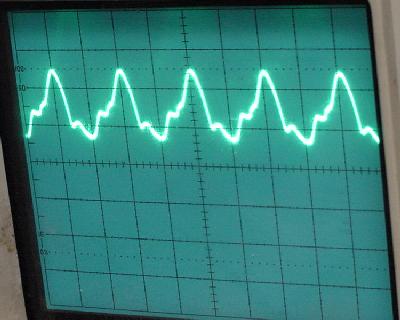
Clock at U3 pin 4 (Time division and delay both set to .2 on a Tek 465 scope).
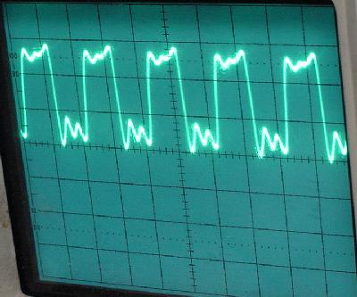
Clock at TP5 (Time division and delay both set to .2 on a Tek 465 scope).
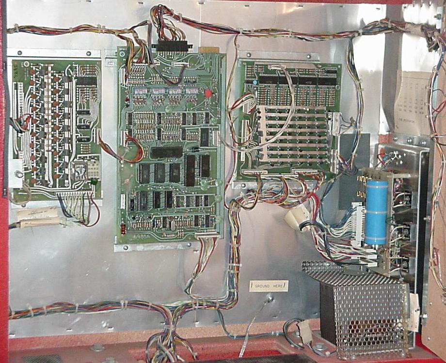
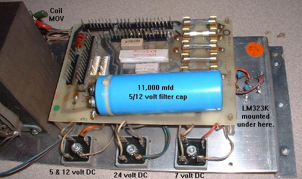
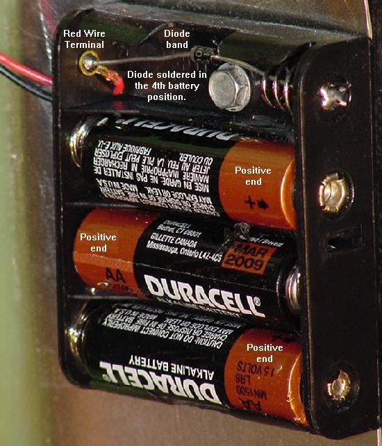
Zero Cross Circuit.
The MPU board requires 24 volts DC (+/- 6 volts) solenoid voltage to boot. This is
used for a zero cross circuit. Even though the 24 volts is DC, it is not filtered
with a filter capacitor. The voltage comes from the transformer and goes through a
bridge rectifier on the power supply board. The bridge "full wave rectifies"
the AC transformer voltage into rough DC. This rough DC is required for the zero
cross circuit - if a filter capacitor was used to smooth the 24 volts, the
zero cross circuit would not work!
Make sure there is 24 volts DC at the MPU board connector J1 pin 3. Also measure
TP6 (located below U3) for about 4.9 volts DC. A bad U2 chip (LM339) or U3 (74LS04)
can cause the zero cross circuit to fail.
Check the MPU Board Test Points.
Other test points to check are the following. This applies
to both MPU-1 and MPU-2.
- TP6 (located below U3, zero cross). Should be about 4.9 volts DC. If not check
for 24 volts DC at J1 pin 3.
- TP5 (located to the right of U11, clock circuit). CLOCK Test Point!
Should be about 2.1 volts. If not check U3 (74LS04).
- TP4 (located below U7, reset circuit). RESET Test Point! Should be 5 volts. If not suspect
one of the reset transistors QA,QB,QC (2N3904) and QD (2N4403). Also U3 (74LS04)
or U5 (74LS32) could be bad.
- TP3 (located below U8, reset circuit). Should be 0 volts. This is the
"Anti RESET Test Point", that is if Reset is high (as it should be),
this test point will be low. If not suspect one of the reset
transistors QA,QB,QC (2N3904) and QD (2N4403).
- TP1 = 5 volt power (4.9 to 5.2 volts DC).
- TP2 = 12 volt power (11 to 14 volts DC).
- J1 pin 3 = 24 volts (22 to 30 volts DC).
- TP7 = ground.
Reset, Clock, Zero Cross Test Points Check Out OK.
If everything so far checks out, the MPU board should be getting
at least one flash from the LED (indicating a good reset, clock and
zero cross circuits). If not I would suspect U11 (Z-80 CPU),
U6/U7 RAM (6551), or U17 (8255 PIA). It would also not be a bad idea
to replace the game ROMs at U12,U13,U26.
Best to jumper the MPU board for 2716 EPROMs (as shown
below) and burn new 2716 game EPROMs.
This excerpt by Jeremy Fleitz.
If the Red LED did not flash at all, check the reset on the Z80 and the Z80-CTC.
These are both the same and can be checked with a voltmeter at TP4, it should
be 5 volts. The
Oscillation at this TP is created by u2 (LM339).
This oscillation drives the resets of each of the Z80 and the Z80 CTC until
they synchronize with the fourth clock enable on the displays (actually from
the PPI). Once established, the LED can start to flash, as the Z80 and the Z80 CTC
establish a good synch with the rest of the system. When this happens the reset
should go high and stay high. TP3 (the "anti Reset") should be the reserve (low).
It should Oscillate, and then go low and stay low. This all should happen within
three seconds maximum. If this is not, then check the following:
- Check the ROM chips. If the are hot that is a bad sign. But original black
ROMs should immediately be suspect.
- Check the +5 volts at the MPU board at
TP1 (+5 volts DC located lower right corner by J1) and
TP7 (Ground test point located below third DIP switch bank from the left).
- Check and/or replace the Z80CTC.
- Check the oscillation clock circuit. Should have a BandWidth of approximately .2 ms
or 5 hz (see the oscilliscope pictures above).
- Check and/or replace the 6810 RAM Chip at U8. Actually just remove it, as the board
will start to flash without the 6810 RAM.
- Check the 74154 chip at U14 (next to connector J2). This
chip is mainly responsible for the Clocks for the switches on the Game
Board. If your switches aren't working, this is likely the problem.
- Check the pins on each socketed IC. These sometimes become tarnished
due to battery corrosion.
- Check all of the diodes below the DIP switches and the DIP switch settings on the MPU.
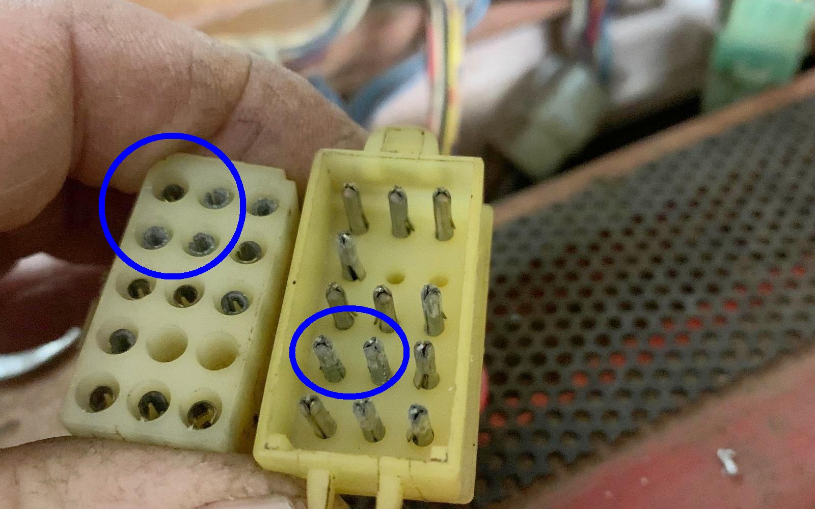
The J1 Power Connector and Lack of LED flashes.
The lower right J1 power connector is the only connector the MPU-1
or MPU-2 needs to show six LED flashes. A very common problem with this
connector is pin 1 (the pin furthest to the left) breaks off
the MPU header. If this pin is missing/broken from the J1 connector,
the MPU board will not flash even once!
MPU Board LED Flashes Explained.
Of course this all assumes you have a valid reset and clock signal.
See above for details.
GamePlan MPU LED Flashes.
If there is no LED flashes, check the MPU board voltages first for
+5 and +12 volts DC. Then verify that the LED is good. This is done
easily by just replacing the LED. Or you can short the top leg of the
transistor just below the LED to ground (this will light the LED, if it is good.)
I must note that GamePlan hardware around the MPU LED is different than
say Bally. For example, Bally's hardware turns on the diagnostic MPU LED
at power-on. Meaning you get a Bally "locked on" LED if the softare is
not running. GamePlan does not do this... If the software is not running
(bad reset or clock or whatever), the MPU diagnostic LED does not come on!
This gives a truely "dead" view of the board. Just keep that in mind...
MPU LED Flash 1.
The first MPU LED flash indicates the reset, clock and zero cross circuits are
working properely. If there is no first flash, see the section above for
explainations of repairing the reset, clock, or zero cross circuits.
Also be sure to check the MPU board is getting 4.9 to 5.2 volts (TP1), 12 volts (TP2),
and 24 volts (J1 pin 3), and ground (TP7).
MPU LED Flash 2.
The second MPU LED flash indicates the zero cross over pulse is OK.
If no second MPU LED flash, look for 25 volts DC at MPU connector J1 pin 3,
usually because of a bad 25 volt rectifier board fuse for the coil voltage.
A bad U10 (Z80CTC) can cause no second LED flash.
Also check chips U3 (74LS04) and U2 (LM339).
Last check for a failed U11 (Z80), U6/U7 (6551),
U12/U13/U26 (Game ROMs), or U17 (8255 PIA).
MPU LED Flash 3.
The third MPU LED flash indicates that U6 and/or U7 (6551) CMOS RAM chips are good.
If there is no 3rd flash, chances are good U6 and/or U7 are bad
(note if either U6/U7 6551 chips are missing, the MPU board won't even give one LED flash).
In addition U9 (74LS32) could be bad.
MPU LED Flash 4.
The fourth MPU LED flash indicates that U8 (6810 RAM) is good. No 4th flash
and U8 is probably bad. It could also
be a problem with the 6810 selection chips U5 (74LS32) or U24 (74LS04).
Note the U8 (6810) chip is about the only MPU board chip that can be
completely missing and the MPU board will boot with up to four flashes.
Also note it is possible that you may have a MPU-1 board without a 6810,
and that's OK. In this case you'll still get flash#4 as if you have a good 6810.
MPU LED Flash 5.
The fifth MPU LED flash indicates the I/O is good, which is handled by
the Peripheral Interface Adaptor (PIA) chip 8255 at U17. If there is no 5th flash,
replace the U17 (8255 PIA) chip. Could also be the I/O chip select gate
at U4 (74LS00). Hence if you replaced the 8255 at U17, then the 74LS00 at U4 is likely bad.
MPU LED Flash 6.
The sixth MPU LED flash indicates the game ROMs at U12,U13,U26 are good.
I find this somewhat strange that the ROMs are tested so late in the
boot-up procedure. Because if any of the game ROMs are bad, usually
the MPU board's LED will not even flash the first time.
But if there's no sixth MPU flash, replace the game ROMs with 2716 EPROMs using
the procedure below. Could also be U14, U16, U20, U21, U15, U19,
U22, U18 or U23.
Power-On Sound Tune.
The last boot up indicator is not handled by the MPU board LED, but
is a boot-up sound played by the game's sound card. If the boot-up
sound does not play after the 6th MPU LED flash, first check
that MPU board connector J4 is attached (this connector goes
to the sound board). Also make sure the sound board has
all of its connectors attached, and that the volume is turned up.
If there is no 24 volts DC this can be a problem too.
If still no boot-up sound, then check MPU board
U14 (Z80CTC), U16 (74LS138), U20 (74LS379), U21 (74LS379), U15 (7417),
U19 (74LS00), U22 (7416), U18 (LM339) and U23 (LM339).
End of LED Flash Sequence.
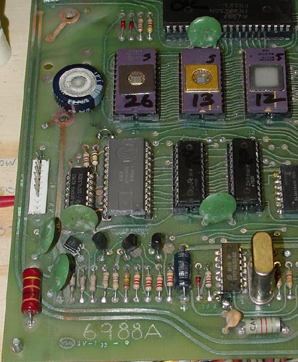
ICs on the MPU board.
Unfortunately Gameplan did not do a great job of labeling their
parts or having layout diagrams.
- U1 - 74LS123
- U2 - LM339
- U3 - 74LS04
- U4 - 74LS00
- U5 - 74LS32
- U6 - CMOS RAM HM6551-9
- U7 - CMOS RAM HM6551-9
- U8 - 6810 RAM
- U9 - 74C32 (CMOS TTL) or 74hc32
- U10 - Z80 CTC
- U11 - Z80 CPU
- U12 - ROM A
- U13 - ROM B
- U26 - ROM C (MPU-2 only)
- U14 - 74154
- U15 - 7417
- U16 - 74LS138
- U17 - 8255 PIO
- U18 - LM339
- U19 - 74LS00
- U20 - 74LS379
- U21 - 74LS379
- U22 - 7416
- U23 - LM339
- U24 - 74LS04 (MPU-2 only)
- U25 - 74LS32 (MPU-2 only)
Converting the 6551 RAMs to 5101 RAMs.
This allows you to use two 5101 RAMs instead of the stock 6551-9 CMOS chip at U6 and U7.
The 6551-9 is almost impossible to purchase, but the 5101 is more
readily available.
The 6551 is a very similar cousin to the 5101 CMOS static RAM. Both are
256x4 bit. The only difference is the second chip select line (CS2, pin 17)
is active low on the 6551, and active high on the 5101. So to use the 5101
we just need to take U6 and U7 pin 17, run it to a hex inverter (74LS04)
to invert the low signal to high.
Procedure by J.Robertson. Original procedure tested and I can NOT get it to work.
I talked to John about this and here was the solution:
Turns out the 5101 has to have the OE pin the inverse of the R/W pin.
In order to do this involved adding a 74LS04 or 74HCT04 chip to
the MPU-1 or MPU-2 board. It's messy, but apparently it does work.
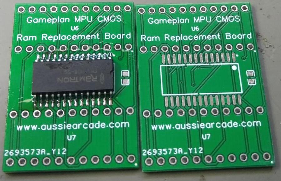
Note before we go down this road, there is probably a better solution.
You can use an NVram with an adaptor board. Apparently this plugs right
into the two 6551 RAM sockets without any modifications. I have not
tried this, but it would be the best possible solution, as no batteries
would ever be needed.
NVram replacement board for GamePlan.
5101 RAM Replacement Instructions:
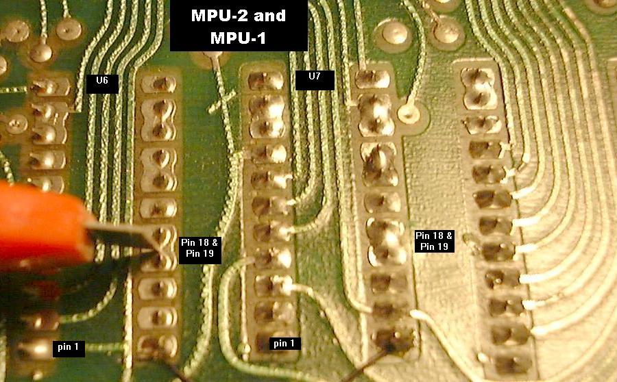
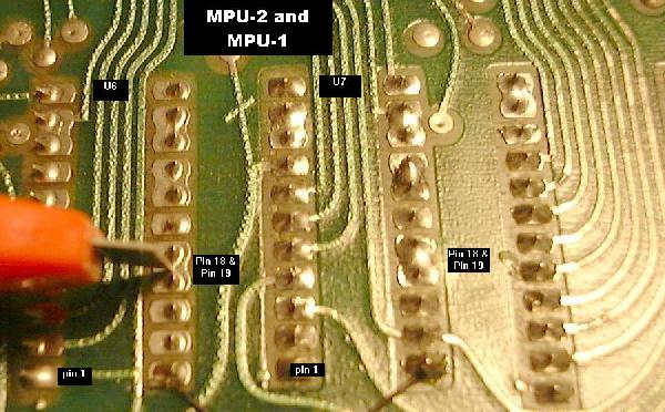
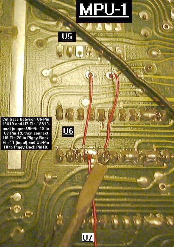
- On the parts side of the MPU-1 or MPU-2 board, find U6 and U7 (the RAM chips).
Cut the trace between U6 pins 18 & 19, and U7 pins 18 & 19. Use a DMM to verify
the cut is complete.
Step 1: Cutting the trace between pin 18 & 19 of U6 and U7.
Picture by JRR.
|
|
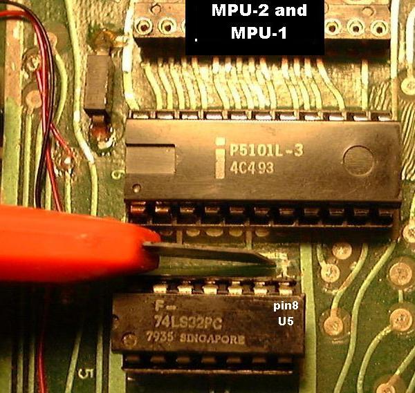
- On the component side of the MPU-1 or MPU-2 board, find and cut the
trace going to U5 pin 8 (74LS32) about 1/4" from the chip.
Step 2: Cutting the trace going to U5 pin 8 (74LS32).
Picture by JRR.
|
|
- Now things get a bit tricky and messy, because there are not enough
spare unused TTL games on the MPU-1 and MPU-2 board for this conversion.
Because of this we need to add a 74LS04 chip to both the MPU-1 and MPU-2.
In order to do this in the most space efficient manner, a new 74LS04 hex inverter chip
can be added right on top of the existing U5 chip on the MPU-1 and MPU-2 board.
This new "piggyback" chip will give us the needed inverter gates to complete
the conversion. To do this in the most effective way, bend ALL the pins of
the new 74LS04 piggyback chip UP, except for pins 7 and 14. Piggyback pin 7
should be soldered directly to U5 pin 7 (ground). Piggyback pin 14 is also
soldered directly to U5 pin 14 (+5 volts). The rest of the piggyback pins
are the inverter pins, used in pairs, giving us six inverter gates
(one pin is an input, the other pin an output). This includes pins 1,2 and 3,4 and
5,6 and 8,9 and 10,11 and 12,13.
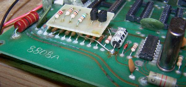
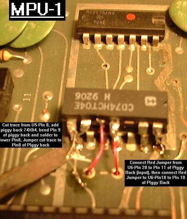
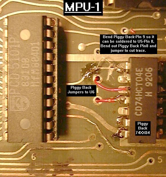
MPU-1 mods to component side - add 74LS04 (known as "Piggyback") on top of U5.
For the MPU-1 PCB connect Piggyback pin 9 to U5 pin 8 (which was cut from its
trace in the previous step). Bend out Piggyback Pin 8 and add a jumper to the cut trace
formerly going to U5 pin 8.
This is almost identical to the MPU-2 mods except that MPU-2 has a spare inverter
gate on U24 that we will use to invert U6/7-Pin17, thus we will only need one gate
on the Piggy Back 74LS04 chip.
Step 3 MPU-1. Picture by JRR.
|
|
Step 3 MPU-1. Alternate picture showing cut trace at U5-Pin8 and jumper to
Piggyback-Pin 8 and jumpers to U6-pins 20 and 18 as described below.
|
|
Step 3 MPU-1. Mods to underside of MPU board (same solder pad cuts as MPU-2 below).
|
|
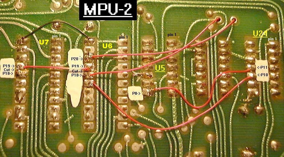
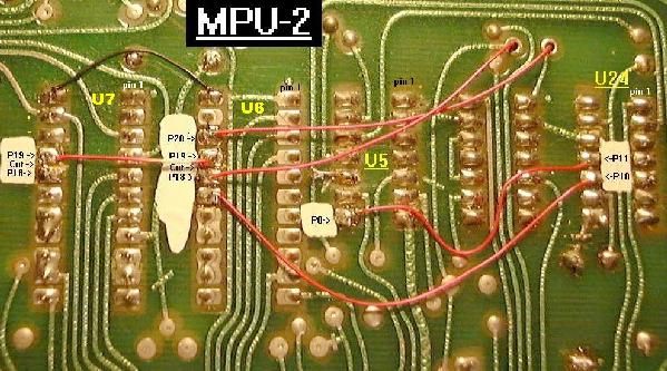
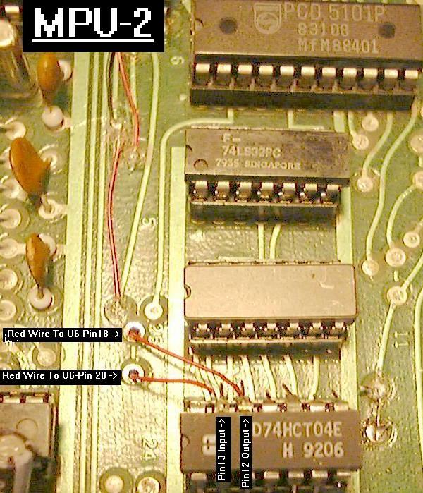
- MPU-2: Add jumpers between U6 pin 20 and Piggyback pin 11.
Then jumper between U6 pin 18 and Piggy Back-Pin 10.
This sets up the OE pin so it is the opposite of R/W.
Add jumper between U6 pin 19 and U7 pin 19 (note that U6 pin 18 and U7 pin 18
are already connected with a trace on the top side of the PCB).
Next jumper U5 pin 8 to U24 pin 11.
Finally jumper U24 pin 10 to U6 pin 17.
Step 4 MPU-2. Picture by JRR.
|
|
Step 4 MPU-2.
|
|
From John: Found a way to get rid of the Piggyback 74LS04.
Simply run a jumper from U6 pin 18 (5101 OE) to U11 pin 21 (CPU /RD pin).
Oh great John, NOW you tell us!
Bad MPU Board Disc Capacitors.
The Gameplan MPU board uses a number of (usually) green 104 (.1 mfd 16 volt) disc
capacitors. Just be aware that these can short and drag the 5 volt bus
down, giving strange boot up results. These caps can not be tested in
circuit. So if there is any questions about them, just replace them all
(they are inexpensive).
Reseting the High Score/Credits and Audits.
While a Gameplan game is powered on and in attract mode.
Press the red switch S33 on the MPU board at the upper right
hand corner. This will reset all high scores and
remove any unused credits from the game. To reset any
audit, use the game's test button in the coin door
to advance to the audit to be cleared. Then press the MPU S33
red switch to clear that audit.
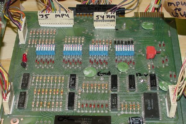
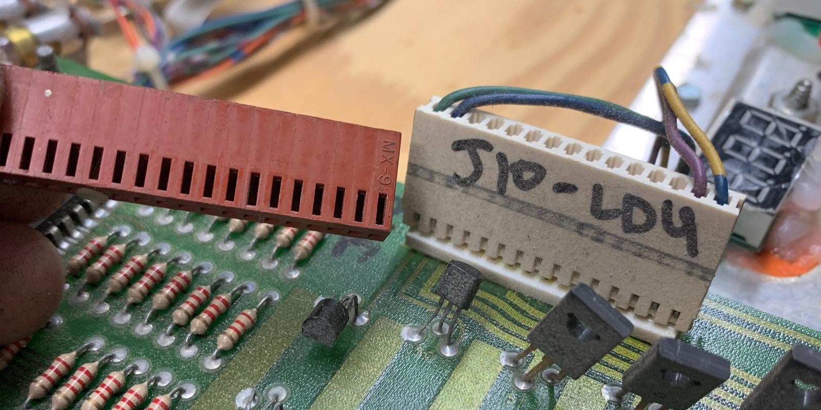
MPU Board Connectors.
The following are the connectors used on Gameplan MPU boards.
- J1 - bottom right, .100" Molex 15 pins. Main power
connector for the MPU board.
- J2 - right middle, .100" Molex 9 pins. Connection to
the lamp driver board.
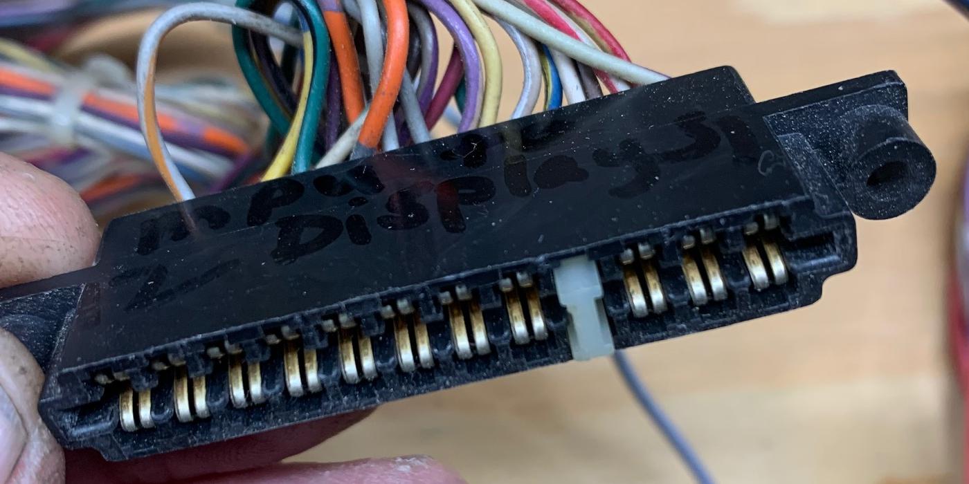
- J3 - top right, card edge connector. Used on cocktail
pinballs only for the DDU score displays.
- J9 - top middle, card edge connector (MPU-2 only). Used for
upright pinballs only for the BDU score displays.
- J4 - top middle, .100" Molex 9 pins. Goes to sound board.
- J5 - top left, .100" Molex 15 pins. Switch matrix plug
for the playfield switches.
- J6 - left top, .100" Molex 9 pins. Slam, tilt, coin, credit,
test switches.
- J7 - left middle, .100" Molex 9 pins. Connection to
the Solenoid Driver board.
- J8 - left bottom, .100" Mole 9 pins. Used only for -5 volt power
supply if MPU board is using TMS2716 EPROMs (tri-voltage EPROMs).
3b. When Things Don't Work: Game ROMs, EPROMs, and Jumpers.
Most GamePlan MPU boards use some sort of 2316 (black PROM) or 2716 style ROM set up.
From Attila the Hun to Andromeda, all GamePlan MPU boards used a 2732 ROM in U13 (no ROM in U12)
and a 2716 ROM in U26 (with a few exceptions.)
Finally with Cyclopes, all three ROM sockets went to 2732s
(Cyclopes being the only GamePlan configured this way.)
If a machine was originally configured to use 2716s (all games before Attila the Hun),
it is best to stay with 2716s. That is do not change to 2732s by combining the ROM files.
You can do this, but it's just not suggested. Likewise,
if the game originally used 2732 (Attila the Hun to Andromeda), it's best to use 2732
and not changed to two 2716s by splitting the ROM file.
Using "regular" 2716 EPROMs instead of Masked ROMs or TMS2716 EPROMs.
Standard 2716 EPROMs can be used on the MPU-2 board instead of the
black masked 2316 ROMs at U12 (PROM A), U13 (PROM B) and U26 (PROM C).
To use 2716s just requires cutting two traces and installing two jumpers.
The only caution is do *not* use TMS2716 EPROMs for this procedure.
(TMS2716 EPROMs require -5, +5 and 12 volts to operate and
are not pin compatible with "normal" 2716 EPROMs, and require a small -5 volt
power supply board connected to the MPU at J8. Note that TMS2516
*are* compatible with standard 2716 EPROMs.) If the game originally used
TMS2716 EPROMs and is converted to standard 2716 EPROMs, the small -5 volt
power supply board attached to the MPU board at J8 can be removed.
This procedure was documented by Clive Jones.
Note the Gameplan MPU board can be jumpers for other styles of ROMs.
This includes 2316 or 2332 black ROMs, 2532 EPROMs, or TMS2716 EPROMs (but these
require an auxiliary -5 volt power supply which connects to the MPU
board at the otherwise unused J8 connector next to the 6810 RAM at U8).
Because none of these three ROM/EPROMs are common, I don't recommend
any replacement but using standard 2716 (or TMS2516) EPROMs, which
are commonly available and easily programmed.
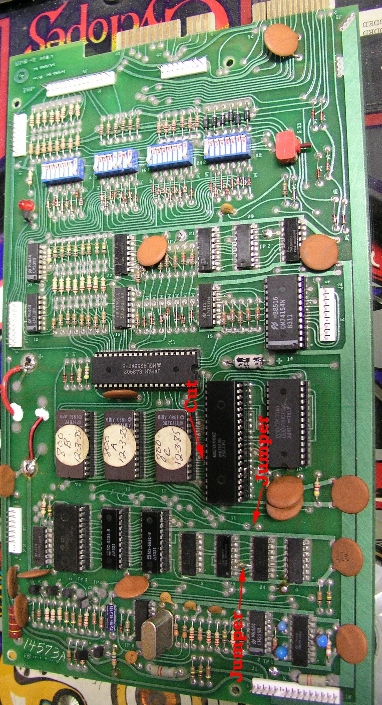
Modifying a MPU-2 board for EPROMs. Pic by Clive.
|
|
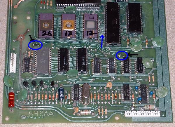
Modifying a MPU-2 for "standard" 2716 EPROMs at U12, U13 and U26.
- On the *component side* of the MPU board and directly to the left of
and between U11 pins 34 & 35 of the Z80 microprocessor is a single trace
ending at a via (pad). Cut the trace at the via so the trace and the via are
separated. Check that they are no longer connected with a DMM's continuity setting.
Double check that TP7 (ground) does not connect to pin 21 of any of the game ROMs (u12/u13/u26.)
- On the *solder side* of the board, cut the trace connecting U24
pin 8 (74LS04) to the pad above it. (There is only one
connection to pin 8 on the solder side.) Note there is a line screened onto
the board that goes through this trace (like GP knew you would be cutting this
trace!) Check the pin is no longer
connected to the via using a DMM's continuity setting, and
there should be no continuity between U24 pin 8 and U13 pin 18.
- On the *component side* of the MPU board, add a
jumper across the two pads to the lower left of chip U26.
Again there is a line screened on the board that goes between these
two pads, encouraging this jumper. Check your work by testing
continutity between TP1 (+5v) and pin 21 of the game ROMs (u12/u13/u26.)
- On the *component side* of the MPU board, add a
jumper across the two pad to the left and above chip U24.
Again there is a line screened on the board that goes between these
two pads, encouraging this jumper. Check your work by getting
continuity between U25 pin 8 and U13 pin 18.
- Install 2716 EPROMs at U12, U13 and U26.
Steps 1,3,4 component side: modifying a MPU-2 board for 2716 EPROMs.
|
|
Step 2 solder side: modifying a MPU-2 board for 2716 EPROMs.
|
|
Modifying a MPU-2 for "standard" 2732 EPROMs at U12, U13 and U26.
Some of the newer GP machines like Cyclopes uses larger EPROMs (2732).
I have not personally tested this procedure but it has worked for
one user.
Component Side Modifications:
- Find the trace between U24 pin 13 and U25 pin 2 (trace often has a line
through it). Sometimes this trace is cut, sometimes it's not. Make sure it's not cut.
- Connect jumper above U24 pin 8 (if cut, which it often is). This
connects U24 pins 8/9 together.
- To the left of and between U11 pins 34 and 35 of the Z80
is a trace ending at a via (pad). Cut the trace at
the via so the trace and the via are separated.
- I've seen some boards with the 3rd trace from
U26 pin 1 cut. This trace should not be cut.
Solder Side Modifications:
- Install a jumper wire from U24 pin 11 going to U11 pin 3.
- Install a jumper wire from U24 pin 10 to pad inside the "loop" below U25 pin 1.
- Cut trace on previous pad AFTER U25 pin 13 trace (where the "slash" line is
in the trace).
- Cut trace U24 pin 8 to the pad above it (there is a line going thru this trace).
- Install a jumper wire from U12 pin 21 to the pad between and to the right of U11 pins 39/40.
Component side: modifying a MPU-2 board for 2732 EPROMs.
Pic by Tom.
|
|
Solder side: modifying a MPU-2 board for 2732 EPROMs.
Pic by Tom.
|

|
ROM Files.
ROM (EPROM) files are available for most Gameplan games, and
can be burned into 2716 EPROMs. Note the MPU board will need to
be jumpered for 2716 EPROMs, as indicated above. Cyclopes will
need to be jumpered for 2732 EPROMs, as indicated above.
Some files use the notation "A" (U12), "B" (U13) or "C" (U26) for the 2716 EPROM files.
Also some files have an "AB" (U13) ROM which is A and B combined
into a single 2732 EPROM, so the "A" (U12) ROM is not needed (additional
some jumper modifications will be needed to use a 2732 at U13).
The 2716 files were combined into a 2732 file using the following MS-DOS command:
Copy /B romU12.716 + romU13.716 romU13.732
Games using a MPU-1 ROM software
can be used in a MPU-2 (ROM socket U26 will be empty), and it works fine.
Because of this the MPU-2 is much more
versatile as it can be used in any Gameplan game. The MPU-1 board though can not
be used in games calling for a MPU-2, because of the limited ROM space in the MPU-1
board.
3c. When Things Don't Work: The Built-In Diagnostics/Bookkeeping.
Press the Red test button inside the coin door will activate the game's
audits and diagnostic functions. For this to work though the game *must*
be in "game over" (attract) mode, otherwise the test switch does not respond.
The number of the audit or test is shown in the ball-in-play display.
If an audit, the value of that audit is shown in all four of the player
score displays. If the game is left in an audit for more than 30 seconds,
the MPU will go back to attract mode automatically (this applies to the
audit functions only, not the diagnostic functions).
Any audit function can be reset by pressing the red S33 button on the
MPU board while that audit is displayed (though some games do have an
audit reset button inside the coin door too).
Games With the Ones Digit Permanently Programmed to Zero.
Here the list of Gameplan games where the ones digit of the
four score displays is permanently programmed to show "0",
regardless of what function the game is performing.
This will affect some audit numbers, and many confuse the user
during diagnostics (especially while testing the score displays).
- Cocktail 110 models (Black Velvet, Real, Rio, Camel Lights,
Chuck-a-Luck, and Foxy Lady)
- Coney Island!
- Super Nova
- Pinball Lizard
- Sharpshooter
- Sharpshooter 2
- Star Trip / Family Fun
- Vegas
- Global Warfare
Audits
Audit values and orders are MPU software dependent, with games designed
originally with a MPU-1 starting audits at
button press #5, and MPU-2 designed games starting audits at button press #1.
Gameplan does have a general audit scheme that applies to many games.
Also be aware that many Gameplan games have the "ones" digit permanently
programmed to zero (so don't include that zero in the audit number -
this does not apply to replay/high score levels).
For example if Total Plays says "006210", that means there were 621
total plays. Note that replay levels are reset by the red MPU switch and
can be changed by 10,000 points using the credit button.
MPU-1 Audit numbers:
- Replay level 1 (resets to a set value by pressing S33)
- Replay level 2 (resets to a set value by pressing S33)
- Replay level 3 (resets to a set value by pressing S33)
- High score to date
- Number of credits currently on game (000110 = 11 credits)
- Total plays (010220 = 22 plays)
- Total replays (010390 = 39 replays)
- Number of times high score has been exceeded (000030 = 3 times)
- Coin counter 1 (011130 = 113 coins)
- Coin counter 2 (010000 = 0 coins)
- Coin counter 3 (012950 = 295 coins)
MPU-2 Audit numbers:
- Coin counter 1
- Coin counter 2
- Coin counter 3
- Total plays
- Total replays
- Replay level 1 (resets to a set value by pressing S33)
- Replay level 2 (resets to a set value by pressing S33)
- Replay level 3 (resets to a set value by pressing S33)
- High score to date
- Number of times high score has been exceeded
- Number of credits currently on game
- Number of times Replay level #1 was exceeded*
- Number of times Replay level #2 was exceeded*
- Number of times Replay level #3 was exceeded*
* Some game software does not go above audit #11.
Diagnostics
The display test will put a number "0" to "9" in each and every
one of the score LEDs (unless the game was programmed with
the ones to be permanently "0", in this case the ones digit
will always show "0"). The lamp test will flash ALL lamps on and off
(if using a test fixture, all 63 lamps will flash on a LDU-2 and all
47 on a LDU-1). The solenoid test will pulse each CPU controlled
coil in the game (does not energize mechanical coin counters).
The switch test will show any closed switch, so it's best to
have all switches open when this test is started (since the score
LEDs can only show one closed switch at a time).
Here is a list of the diagnostic functions for each Gameplan pinball
I had the opportunity to test.
Cocktail 110.
The ones digit on the cocktail 110 games is always zero,
even during test and audit mode. There is a pair of DDU-1
dual display boards (each board has two player displays
for a total of 4 players). If this software is run
in a test fixture or upright pin, the player 1 display
will be all zeros and not used. The ball/credit display
becomes the 4th player display.
Game cycles NONE of the CPU controlled lamps during attract mode.
- 1st Test button press.
Lamp test for up to 47 feature lights using the LDU-1 board.
- 2nd Test button press.
Display test on the two DDU-1 boards (ones digit always zero).
- 3rd Test button press. Solenoid test.
- 010 = Q6
- 020 = Q1
- 030 = Q12
- 040 = Q13
- 050 = Q3
- 060 = Q10
- 070 = Q5
- 080 = Q14
- 090 = Q4
- 100 = Q16
- 110 = Q7
- 120 = Q15
- 130 = Q17
- 140 = flipper relay Q19
- 150 = all CPU controlled lamps On
- 160 = all CPU controlled lamps Off
- 4th Test button press.
Switch test.
- 5-15 = Game Audits.
Agent777
Game cycles all the CPU controlled lamps during attract mode.
- 01-14 = Game Audits.
- 15 = Lamp test for feature lights.
- 16 = Display test (ones digit does cycle 0-9).
- 17 = Solenoid test.
- 01 = Q14
- 02 = Q12
- 03 = Q6
- 04 = Q2
- 05 = Q3
- 06 = Q17
- 07 = Q13
- 08 = Q11
- 09 = Q10
- 10 = Q1
- 11 = not used during diags (possibly mechanical coin counter).
- 12 = not used during diags (possibly mechanical coin counter).
- 13 = not used during diags (possibly mechanical coin counter).
- 14 = flipper relay Q19
- 15 = all CPU controlled lamps On
- 16 = all CPU controlled lamps Off
- 18 = Switch test.
Coney Island!
Game cycles only about 10 CPU controlled lamps (one at a time)
during attract mode.
Score displays ones digit is always a zero.
- 01-11 = Game Audits.
- 12 = Lamp test for feature lights.
- 13 = Display test (ones digit alway zero).
- 14 = Solenoid test.
- 010 = Q6
- 020 = Q16
- 030 = Q7
- 040 = Q14
- 050 = Q4
- 060 = Q17
- 070 = Q5
- 080 = Q15
- 090 = Q12
- 100 = Q13
- 110 = Q3
- 120 = Q10
- 130 = not used during diags (possibly mechanical coin counter).
- 140 = not used during diags (possibly mechanical coin counter).
- 150 = not used during diags (possibly mechanical coin counter).
- 160 = flipper relay Q19
- 170 = all CPU controlled lamps On
- 180 = all CPU controlled lamps Off
- 15 = Switch test.
Captain Hook.
Game cycles all the CPU controlled lamps during attract mode.
- 01-14 = Game Audits.
- 15 = Lamp test for feature lights.
- 16 = Display test (ones digit does cycle 0-9).
- 17 = Solenoid test.
- 01 = Q14
- 02 = Q12
- 03 = Q2
- 04 = Q11
- 05 = Q10
- 06 = Q13
- 07 = Q3
- 08 = Q1
- 09 = Q18
- 10 = flipper relay Q19
- 11 = all CPU controlled lamps On
- 12 = all CPU controlled lamps Off
- 18 = Switch test.
Attila the Hun
Game cycles all the CPU controlled lamps during attract mode.
- 01-11 = Game Audits.
- 12 = Lamp test for feature lights.
- 13 = Display test (ones digit does cycle 0-9).
- 14 = Solenoid test.
- 01 = Q6
- 02 = Q2
- 03 = Q11
- 04 = Q10
- 05 = Q12
- 06 = Q4
- 07 = Q7
- 08 = Q17
- 09 = Q15
- 10 = Q1
- 11 = not used during diags (possibly mechanical coin counter).
- 12 = not used during diags (possibly mechanical coin counter).
- 13 = not used during diags (possibly mechanical coin counter).
- 14 = flipper relay Q19
- 15 = all CPU controlled lamps On
- 16 = all CPU controlled lamps Off
- 15 = Switch test.
Lady Sharpshooter
Game cycles all the CPU controlled lamps during attract mode.
- 01-14 = Game Audits.
- 15 = Lamp test for feature lights.
- 16 = Display test (ones digit does cycle 0-9).
- 17 = Solenoid test.
- 01 = Q14
- 02 = Q15
- 03 = Q4
- 04 = Q7
- 05 = Q17
- 06 = Q5
- 07 = Q1
- 08 = Q18
- 09 = flipper relay Q19
- 10 = all CPU controlled lamps On
- 11 = all CPU controlled lamps Off
- 18 = Switch test.
Super Nova
Game cycles all the CPU controlled lamps during attract mode.
- 01-11 = Game Audits.
- 12 = Lamp test for feature lights.
- 13 = Display test (ones digit always zero).
- 14 = Solenoid test.
- 010 = Q6
- 020 = Q16
- 030 = Q7
- 040 = Q5
- 050 = Q14
- 060 = Q15
- 070 = Q17
- 080 = Q4
- 090 = Q12
- 100 = Q13
- 110 = Q3
- 120 = Q10
- 130 = Q1
- 140 = not used during diags (possibly mechanical coin counter).
- 150 = not used during diags (possibly mechanical coin counter).
- 160 = flipper relay Q19
- 170 = all CPU controlled lamps On
- 180 = all CPU controlled lamps Off
- 15 = Switch test.
Pinball Lizard
Game cycles only about 10 CPU controlled lamps during attract mode.
Ones digit in score displays is always a zero.
- 01-11 = Game Audits
- 12 = Lamp test for feature lights.
- 13 = Display test (ones digit always zero)
- 14 = Solenoid test
- 010 = Q6
- 020 = Q16
- 030 = Q7
- 040 = Q14
- 050 = Q4
- 060 = Q17
- 070 = Q5
- 080 = Q15
- 090 = Q12
- 100 = Q13
- 110 = Q3
- 120 = Q10
- 130 = not used during diags (possibly mechanical coin counter).
- 140 = not used during diags (possibly mechanical coin counter).
- 150 = not used during diags (possibly mechanical coin counter).
- 160 = flipper relay Q19
- 170 = all CPU controlled lamps On
- 180 = all CPU controlled lamps Off
- 15 = Switch test
Sharpshooter and Sharpshooter 2
Game cycles only about 10 CPU controlled lamps during attract mode.
Ones digit in score displays is always a zero.
- 01-11 = Game Audits.
- 12 = Lamp test for feature lights.
- 13 = Display test (ones digit alway zero)
- 14 = Solenoid test.
- 010 = Q6
- 020 = Q16
- 030 = Q7
- 040 = Q14
- 050 = Q4
- 060 = Q17
- 070 = Q5
- 080 = Q15
- 090 = Q12
- 100 = Q13
- 110 = Q3
- 120 = Q10
- 130 = not used during diags (possibly mechanical coin counter).
- 140 = not used during diags (possibly mechanical coin counter).
- 150 = not used during diags (possibly mechanical coin counter).
- 160 = flipper relay Q19
- 170 = all CPU controlled lamps On
- 180 = all CPU controlled lamps Off
- 15 = Switch test.
Star Trip and Family Fun
The ones digit on the cocktail games is always zero,
even during test and audit mode. Uses a pair of DDU-1 dual
display boards (each board has two player displays
for a total of 4 players). If this software is run
in a test fixture or upright pin, the player 1 display
will be all zeros and not used. The ball/credit display
becomes the 4th player display. Attract mode only has
one CPU controlled light that lites.
Game cycles ONE of the CPU controlled lamps during attract mode.
- 1st Test button press.
Lamp test for up to 47 feature lights using the LDU-1 board.
- 2nd Test button press.
Display test on the two DDU-1 boards (ones digit always zero).
- 3rd Test button press.
Solenoid test.
- 010 = Q6
- 020 = Q1
- 030 = Q12
- 040 = Q13
- 050 = Q3
- 060 = Q10
- 070 = Q4
- 080 = Q5
- 090 = Q2
- 100 = Q14
- 110 = Q16
- 120 = Q7
- 130 = Q11
- 140 = Q15
- 150 = Q17
- 160 = flipper relay Q19
- 170 = all CPU controlled lamps On
- 180 = all CPU controlled lamps Off
- 4th Test button press.
Switch test.
- 5-15 = Game Audits.
Vegas
The ones digit on the cocktail games is always zero,
even during test and audit mode. There is a pair of DDU-1
dual display boards (each board has two player displays
for a total of 4 players). If this software is run
in a test fixture or upright pin, the player 1 display
will be all zeros and not used. The ball/credit display
becomes the 4th player display.
Game cycles NONE of the CPU controlled lamps during attract mode.
- 1st Test button press.
Lamp test for up to 47 feature lights using the LDU-1 board.
- 2nd Test button press.
Display test on the two DDU-1 boards (ones digit always zero).
- 3rd Test button press.
Solenoid test.
- 010 = Q6
- 020 = Q7
- 030 = Q16
- 040 = Q11
- 050 = Q17
- 060 = Q15
- 070 = Q14
- 080 = Q10
- 090 = Q3
- 100 = Q13
- 110 = Q12
- 120 = sound
- 130 = sound
- 140 = sound
- 150 = sound
- 160 = flipper relay Q19
- 170 = all CPU controlled lamps On
- 180 = all CPU controlled lamps Off
- 4th Test button press.
Switch test.
- 5-15 = Game Audits.
Global Warfare
Game cycles all the CPU controlled lamps during attract mode.
Ones digit in score displays is always a zero.
- 01-11 = Game Audits.
- 12 = Lamp test for feature lights.
- 13 = Display test (ones digit fixed at 'zero').
- 14 = Solenoid test.
- 010 = Q6
- 020 = Q14
- 030 = not used
- 040 = Q11
- 050 = Q17
- 060 = Q4
- 070 = snd
- 080 = snd
- 090 = snd
- 100 = snd
- 110 = snd
- 120 = snd
- 130 = snd
- 140 = snd
- 150 = snd
- 160 = snd
- 170 = snd
- 180 = snd
- 190 = snd
- 200 = Q10
- 210 = Q12
- 220 = Q3
- 230 = Q7
- 240 = Q16
- 250 = Q5
- 260 = Q15
- 270 = flipper relay Q19
- 280 = all CPU controlled lamps On
- 290 = all CPU controlled lamps Off
- 15 = Switch test.
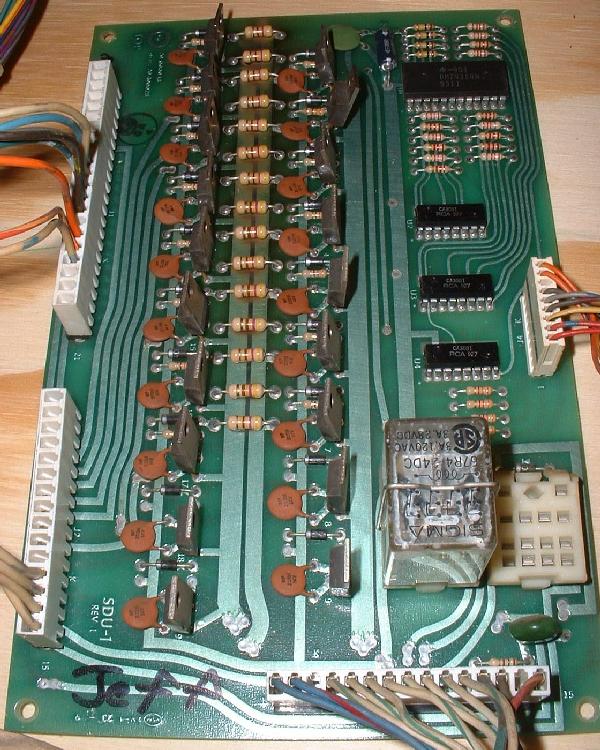
3d. When Things Don't Work: Locked-on or Not Working Coils (SDU).
The SDU board, or Solenoid Driver Unit board,
is very similar to the solenoid section of a Bally -17/-35 solenoid driver board.
The GamePlan SDU consists
of a 74154 chip (4 to 16 line decoder/demultiplexer) which selects which
coil to fire. This then goes to a pre-driver transistor
mounted in a CA3081 chip, and a SE9301 (TIP102) driver transistor.
Coils 1-7 and 10-17 are momentary (that is they go through the 74154 chip),
and the other four coil 8/9/18/19 are continuous with a direct
connection to the MPU's PIA u17 chip. Two of the continuous transistors Q9/Q19
are for driving the two board-mounted relays.
The two other continuous transistors Q8/Q18 are also dedicated control transistors.
By all accounts only one of these was ever used in a production game
(Q8 in Andromeda and Cyclopes.) It doesn't look like Q18 was ever used in any GamePlan game.
The continuous transistors on the
GamePlan SDU are controlled directly by the 8255 PIA on the MPU board.
The PIA u17 pin6 is wired through a 3.3k resistor and then a 1n4004 diode to the
base of Q9 TIP102. PIA u17 pin7 takes the same path to SDU transistor Q19. PAI u17 pin5 takes the
same path to SDU transistor Q18. And while SDU Q8 is wired to J7 pin6 of the MPU, that pin
is not connected to anything on the MPU itself. By comparison, the signal
for the flipper enable relay on the Bally SDB goes through a pre-driver
transistor before getting to the TIP102 transistor.
There is a pair of relay sockets on the SDU, but only one relay socket is populated.
Gameplan was thinking ahead, and only used the second relay socket on
Andromeda (additonal playfield GI lights) and Super Nova (for the roulette wheel).
The flipper relay is controlled by driver transistor Q9, and the empty
socket to its right is controlled by Q19.
The Relay controls the Flippers, with the relay energizing for the duration of a game.
Power for the board and the MPU encoded information comes from connector J3 at the
bottom of the board. Connections to the playfield solenoids is through
connector J1 at the left upper side of the board. And connector J2 on the
left lower side is the return ground path for the flippers.
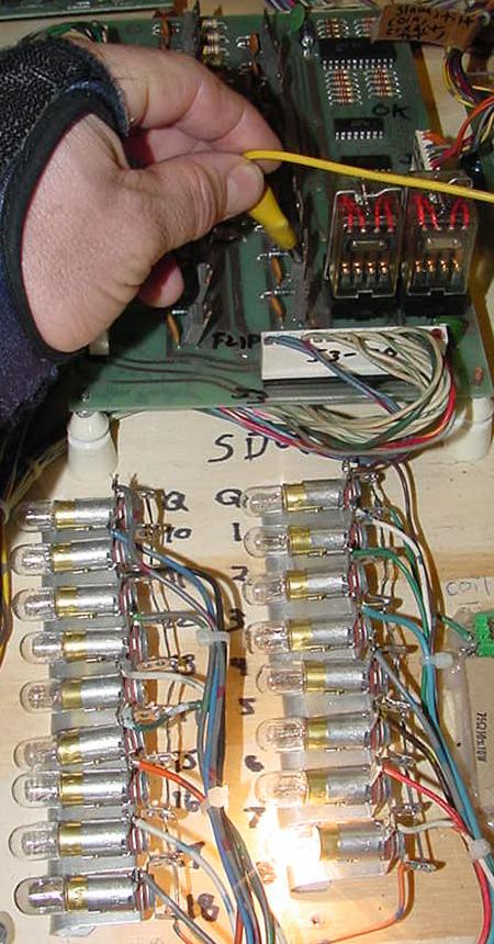
Grounding the metal tab of Q8 SE9301 driver transistor on the SDU,
which energizes the corresponding lamp (coil) on a Gameplan test fixture.
Coil Numbers on Games before Attila the Hun.
Coil numbers of GamePlan games are numbered with an added "0" at
the end of the coil number (and a pre "0" on coil numbers below ten.)
Why did GamePlan add a zero to the end of the coil numbers? Hard to say,
but starting with Attila the Hun, the coil numbers went to a
more normal (and sane) numbering system of 01 to 19 (instead of 010 to 190.)
Diagnosing Coil Problems.
Use the information in the diagnostics section
of this document or the game's manual to determine the transistor
number for the coil in question.
An easy way to determine if a "dead" solenoid problem resides on the SDU board
is to ground a metal tab on any of the SE9301 transistors.
If the solenoid energizes, this shows that the path from the driver
transistor to the solenoid is good (including power to the coil, and the coil itself).
If grounding the transistor tab yeilds nothing, then your problem is either in the
wiring, the coil or the coil's diode, or a lack of power at the coil
(blown playfield fuse).
If the coil is "locked on" (energized) at power-on, or is not working in the
game (but does fire when grounding its corresponding transistor tab), next
suspect the SE9301 driver transistor. IMPORTANT: With the game's power off,
remove connector J1 (upper left) from the SDU board (otherwise false readings can be seen).
Now the transistor can be tested with a DMM's diode function. With the black DDM's lead on
the metal tab (or center leg) of the transistor, a value of .4 to .6 volts DC
should be seen with the red DMM lead on either outside transistor leg.
Any value outside of that range and replace the SE9301 transistor (with a TIP102).
This test is accurate about 95% of the time (note on occasion a transistor can
test as 'good' with this method, and still in fact be bad).
If the coil is still not working or locked-on after replacing the driver transistor,
next suspect the corresponding CA3081 pre-driver transistor chip. Still a problem?
The only thing left is the 74154 decoder chip.
Remember the CA3081 chip is an array of seven NPN transistors, which are the pre-drivers
for the TIP102 power transistors. These chips can be tested as followed using a DMM set to diode function:
| DMM Red Lead |
DMM Blk Lead |
DMM Reading |
| Pin 3 |
Pin 2 |
.60v to .75v |
| Pin 6 |
Pin 4 |
.60v to .75v |
| Pin 8 |
Pin 7 |
.60v to .75v |
| Pin 10 |
Pin 9 |
.60v to .75v |
| Pin 11 |
Pin 12 |
.60v to .75v |
| Pin 13 |
Pin 14 |
.60v to .75v |
| Pin 16 |
Pin 1 |
.60v to .75v |
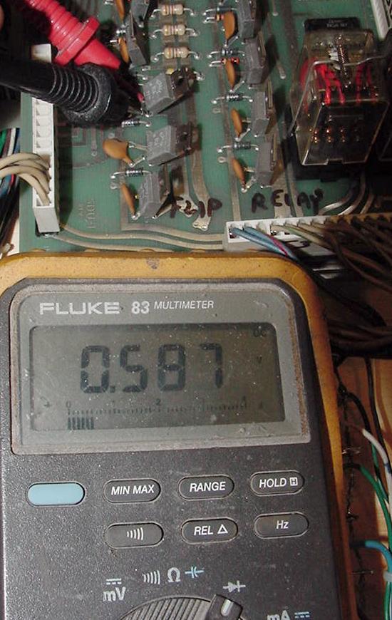
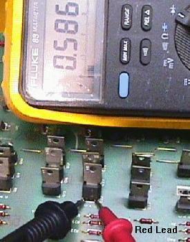
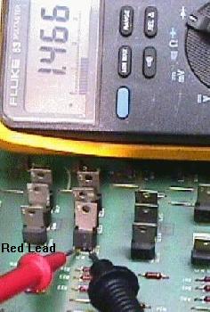
Testing a SE9301 (or TIP102) transistor on the SDU board using the diode function
of a DMM. The black DMM lead is connected to the center leg or metal tab of the
driver transistor. The red DMM lead is connectd to either outside transistor leg.
A reading of .4 to .6 volts DC should be seen. Anything outside of that range and
the transistor should be replaced. Remember to disconnect the SDU J1 connector
before performing this test.
TIP102 vs SE9301.
Anytime a SDU driver SE9301 transistor has failed, replace it with the
more robust and easier to get TIP102 darlington transistor. They are pin for
pin compatible.
Game Fires the Wrong Coil or No Coil.
This is a common problem on Bally games, and less of a problem on
Gameplan pins. The problem can often be seen as the MPU board telling the
SDU to fire a pop bumper, but instead a slingshot fires (or no coils fire). On Bally
games, which use a .100" connector to move the encoded MPU data to the
Solenoid driver board, often the connector is bad and has a worn pin.
But because Gameplan used .156" connectors instead of the whimpy .100"
connectors Bally used, the problem is not as common.
Regardless if the problem is happening on a Gameplan pinball, check all
the connector pins on J1 (bottom right side of the SDU). If just one
pin is broken, this is one bit of encoded information the SDU is not
getting. This will cause the SDU's 74154 chip to decode the wrong
information, and energize the wrong coil (or no coil). If all the J1 connector pins
are in good condition, next suspect the 74154 chip itself.
SDU Connectors.
There are only three connectors on the Solenoid driver unit:
- J1 - .156" Molex connector which is the ground return path from
the playfield solenoids.
- J2 - .156" Molex connector which is the flipper return grounds.
- J3 - .156" Molex connector for the input data from MPU board.
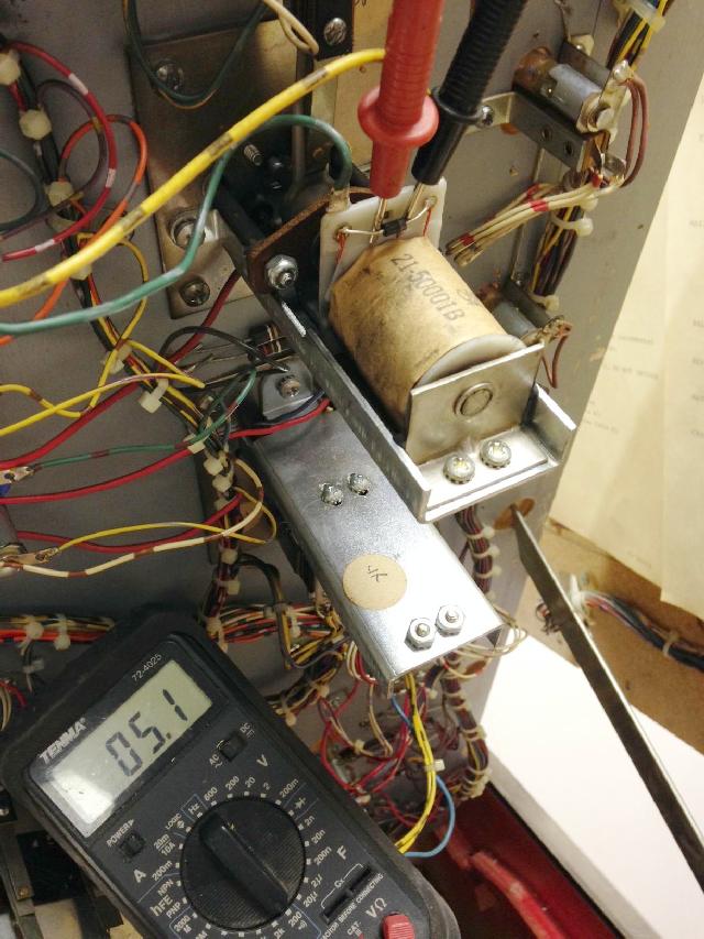
24 volt DC coils used in Gameplan pinballs. Coils with two resistance values are
flipper coils.
Gameplan Coils.
Here's the coils generally used in Gameplan pins. Coils from other
manufacturers can be used if the frame size is the same, and of
course the same relative windings and wire size. Resistance
should be measured from an original coil and compared to the
replacement coil too (replacement coil should be within 20% of
the original coil). Also remember to attach the coil voltage wire
to the lug of the coil with the BANDED side of the 1N4004 diode.
The non-banded diode lug of the coil is the wire that goes
to the driver board's transistor.
- 21-50001B: 24 gauge, 850 turns (Pop Bumper), 4.75 ohms.
- 21-50002B: 25 gauge, 400 turns (power) & 27 gauge, 1000 turns (hold) Flipper. 2.8/13.4 ohms.
- 21-50003B: 25 gauge, 1050 turns (Sling Shot & Ball Kick-Out). 7.45 ohms.
- 21-50004B: 29 gauge, 2000 turns. 33.8 ohms.
- 21-50005B: 27 gauge, 1400 turns (Ball Kicker). 15.4 ohms.
- 21-50006B: 28 gauge, 1800 turns. 25.8 ohms.
- 21-50007B: 24 gauge, 1000 turns. 8 ohms. Larger frame size.
- 21-50008B: 22 gauge, 375 turns (power) & 30 gauge, 800 turns (hold) Flipper. 1.2/21.5 ohms.
- 21-50009B: 23 gauge, 1100 turns (Drop Target Reset). 6.2 ohms. Larger frame size.
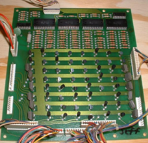
3e. When Things Don't Work: Locked-on or Not Working Feature Lights (LDU).
There are two different SCR's used for lights on the
lamp driver board: the larger MCR106-1, and the smaller
2N5060. They serve the same function, just the larger MCR106-1
can handle more current (and sometimes lights two lamps, while
the smaller 2N5060 can only light one lamp). There is also
a CD4514 CMOS decoder that drives the lamps. Sometimes these
go bad too.
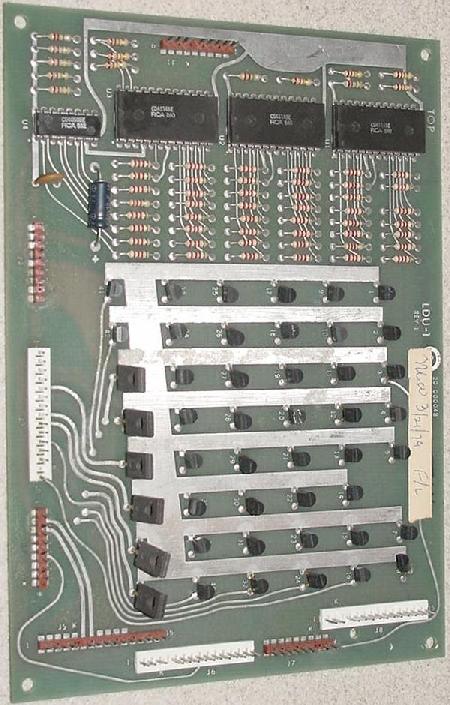
The 45154 puts out an inverted input, and this
drives the SCR (Silicon Controlled Rectifier) for each lamp. There are
three (LDU-1) or four (LDU-2) 45154 chip on the lamp driver board.
Each has a seperate clock, which is controlled by the MPU.
If there are a lot of the lamps not working
(16 or less), there may be a bad 45154 or the Enable wire for that 45154
is bad. The SCRs can be tested with a DMM's diode test.
Why No Lamp Matrix?
Gameplan and Bally didn't use a lamp matrix like Williams did. Gameplan/Bally's approach
was more like Gottlieb's system80, where there was a single
transistor or SCR that drives each lamp.
Because there are up to 63
lamps and 63 SRCs and no lamp matrix, there are a maximum of 64 wires
going to all the CPU controlled lamps (one power wire, and
then a single control wire for each of the lamps).
Replacement SCR's.
Replacement SCRs are available from a variety of sources.
For example, Jameco
sells the MCR106-1 as part number C106Y or C106B1, and
NTE5411 to NTE5416. The smaller 2N5060's replacement number
is 119802 or NTE5400 to NTE5406 (but the NTE version is much more
expensive) or at Mouser part# 610-2n5060.
Also the larger MCR106-1 can be used in place
of the smaller 2N5060, but only if the "A" and "G" legs
are "reversed" (twisted to be reversed, when installed).
This is not recommended, but it can be done in a pinch.
|
NTE SCR Replacements |
|
MCR106-1 NTE Replacements |
|
2N5060 NTE Replacements |
| NTE# |
Voltage |
NTE# |
Voltage |
| NTE5411 |
30 volts |
NTE5400 |
30 volts |
| NTE5412 |
60 volts |
NTE5401 |
60 volts |
| NTE5413 |
100 volts |
NTE5402 |
100 volts |
| |
|
NTE5403 |
150 volts |
| NTE5414 |
200 volts |
NTE5404 |
200 volts |
| NTE5415 |
400 volts |
NTE5405 |
400 volts |
| NTE5416 |
600 volts |
NTE5406 |
600 volts |
The voltage listed above is the repetitive peak reverse
blocking voltage. All the above comparitive NTE SCR's have the same
average on-state current (2.6 amps or 0.8 amps respectively),
and peak gate power dissipation (0.5 watts or 0.2 watts respectively).
|
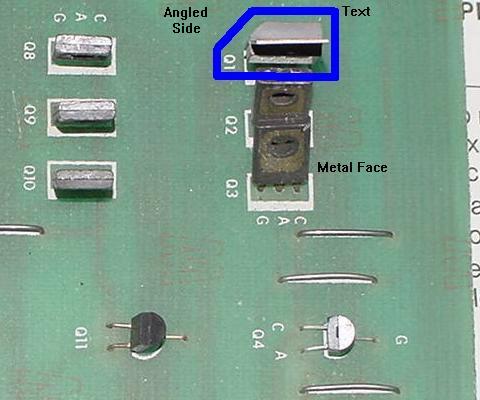
Mounting a MCR106.
There are many styles of MCR106 rectifiers. When mounting the style
without the metal face, note the ANGLE side and the mounting orientation.
The angle sided C106 seems to mount "backwards", compared to the
metal faced version of the MCR106 (because the manufacturer writing seem like it is
on the back of the angled sided SCR). See the picture below.
Mounting of the two styles of MCR105 rectifiers. Note the angled sided
SCR compared to the metal faced SCR.
|
|
The two styles of SCRs used in Gameplan pinballs.
Left: the SCR106-1. Right: the 2N5060.
|
|
Testing the Lamp Driver SCR's, game On.
If a lamp is permanently stuck on, this procedure won't
tell you anything. A lamp that is always on is generally caused
because its SCR has internally shorted. Replace the SCR.
Assuming the game powers on, you can test a non-working
lamp's SCR's to see if it's working (this assumes you have checked the bulb, the lamp
socket, and the wiring to the lamp socket).
- While the game is on and in
"attract" mode, press the Self-Test button inside
the coin door to activate the lamp test.
- Note which feature lamps are NOT working.
The Gameplan self test will flash ALL lamps without exception.
Write down which lamps do not flash.
(You will need this information if several lamps
that connect to the same decoder don't work.
A decoder has likely failed if 4, 8 or 12 lamps, multiples of 4,
are not working.)
- Check the manual's schematics to figure out which SCR number
controls the lamp(s) in question. If not available, look at the wire
color going to the lamp. Then find this wire color on one of the
connectors on the LDU board. From there the connector pin can be
traced back to the exact SCR in question.
- If 4, 8 or 12 lamps that all connect to a single decoder
don't work, suspect the decoder "U" chip as faulty.
- Press the game's test switch again to take the game out
of lamp test mode.
- With the game in out of lamp test,
connect an alligator test lead wire to ground. The large aluminum
transformer plate works well for this.
- Touch the other end of the test lead to the ANODE (A) of the
SCR in question.
- If the lamp does NOT light when the anode is grounded, the
problem is NOT on the lamp driver board. Most likely you have
a wiring problem, a bad lamp socket, or a bad bulb.
Lamp Always On.
- With the game on and *not* in display test,
connect one end of an alligator jumper to ground.
- Connect the other end of the alligator jumper to the GATE (G) of
the SCR in question.
- The lamp in question should turn off.
- If the lamp does not light, the SCR is probably bad.
Test the SCR with the power off using a DMM in diode test, as described below.
If the SCR tests bad, replace it. Repeat steps above 1 to 3.
- If the lamp still won't go out,
replace the decoder chip connecting to the SCR in question. Repeat steps above 1 to 3.
Testing the Lamp Driver SCRs POWER OFF.
Testing the large MCR106-1 lamp driver SCR.
|
|
2N5060 Lamp Driver SCR test:
- Put the black lead of your meter on the "cathode" leg
(labeled "C") of the SCR.
- Put the red lead of your meter on the center "gate" leg
(labeled "G") of the SCR. Your meter should read .4 to .6 volts.
- Swap the meter leads. Now the meter should read 1.4 to 1.6 volts.
If your meter reads anything outside the values above, replace
that 2N5060.
Testing the small 2N5060 lamp driver SCR.
|
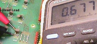
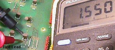
|
3f. When Things Don't Work: Switch Matrix.
The GamePlan switch matrix is a 5 x 8 matrix (like Bally/Stern -17/-35) consisting of a maximum of 40 switches.
There is a total of five switch strobes (columns), starts with 0 and ends with 4.
The eight switch lines (rows) starting with 0 and end with 7. While Bally adopted its numbering
convention for the switches to start at "01" and increase by one in the same strobe, and continue
consecutively to 40, Game Plan added a "0" to the end of its switch numbers for its early games (010 to 400.)
Hence GamePlan switch numbering begins with 010 at strobe/column 0, line/row 0, and increases by 10 in the same column,
consecutively to 400. The switch matrix in all GamePlan games is numbered
like this up to Sharp Shooter II. After that, starting with Attila the Hun, GamePlan
dropped this extra zero and went to two-digit switch numbers (01 to 40, like say Bally.) They also
changed coil numbers to two digits (instead of three) at the same time.
GamePlan Switch Matrix Layout (pre-Attila the Hun)
| |
Strobe0/Col0
J6 pin3/J5 pin6 |
Strobe1/Col1
J5 pin2 |
Strobe2/Col2
J5 pin1 |
Strobe3/Col3
J6 pin9/J5 pin3 |
Strobe4/Col4
J5 pin7 |
Line0
Row0
J5 pin11 |
010
Accounting Reset
on MPU board |
090 |
170 |
250 |
330 |
Line1
Row1
J5 pin9 |
020
Credit Button |
100 |
180 |
260
Diag Button |
340 |
Line2
Row2
J5 pin15 |
030
Slam Switch |
110 |
190 |
270 |
350 |
Line3
Row3
J5 pin15 |
040 |
120 |
200 |
280 |
360 |
Line4
Row4
J5 pin14 |
050
Coin 2 |
130 |
210 |
290 |
370 |
Line5
Row5
J5 pin10 |
060
Coin 3 |
140 |
220 |
300 |
380 |
Return6
Row6
J5 pin12 |
070
Coin 1 |
150 |
230 |
310 |
390 |
Return7
Row7
J5 pin13 |
080
Tilt |
160 |
240 |
320 |
400 |
GamePlan Switch Matrix Diagrams.
One thing really weird about the GamePlan documentation is there is
really no switch matrix diagram. Yes they list the switch numbers
and description, but they don't layout the switches in a matrix.
Personally I miss this, as I find a matrix style chart very helpful
when diagnosing a switch matrix problem.
As an example, here's the switch list shown for Sharp Shooter:
- 010 = accounting reset
- 020 = credit button
- 030 = slam
- 040 = drop target T
- 050 = coin 2
- 060 = coin 3
- 070 = coin 1
- 080 = tilt
- 090 = 10pt scoring
- 100 = drop target E
- 110 = ball return (outhole)
- 120 = A lane
- 130 = R lane
- 140 = P lane
- 150 = sling shot
- 160 = extra ball
- 170 = drop target R
- 180 = special
- 190 = top stand up
- 200 = lower stand up
- 210 = upper pop bumper
- 220 = upper right pop bumper
- 230 = spinner
- 240 = kickout hole
- 250 = loop lane sw#1
- 260 = diagnostics switch
- 270 = loop lane sw#2
- 280 = loop lane sw#3
- 290 = loop lane sw#4
- 300 = loop lane sw#5
- 310 = drop target S
- 320 = drop target H
- 330 = lower top pop bumper
- 340 = lower bottom pop bumper
- 350 = drop target O (left)
- 360 = drop target O (right)
- 370 = S lane
- 380 = H lane
- 390 = 50k lane
- 400 = 1000 Advance lane
...And this breaks down to the following matrix:
| |
Strobe0/Col0
J6 pin3/J5 pin6 |
Strobe1/Col1
J5 pin2 |
Strobe2/Col2
J5 pin1 |
Strobe3/Col3
J6 pin9/J5 pin3 |
Strobe4/Col4
J5 pin7 |
Line0
Row0
J5 pin11 |
010
Accounting Reset
on MPU board |
090
10 pts. |
170
drop R |
250
loop #1 |
330
lower top pop |
Line1
Row1
J5 pin9 |
020
credit |
100
drop E |
180
special |
260
diag button |
340
lower bot pop |
Line2
Row2
J5 pin15 |
030
slam |
110
outhole |
190
top standup |
270
loop #2 |
350
drop O lft |
Line3
Row3
J5 pin15 |
040
drop T |
120
A lane |
200
lower standup |
280
loop #3 |
360
drop O rt |
Line4
Row4
J5 pin14 |
050
coin 2 |
130
R lane |
210
upper pop |
290
loop #4 |
370
S lane |
Line5
Row5
J5 pin10 |
060
coin 3 |
140
P lane |
220
upper rt pop |
300
loop #5 |
380
H lane |
Return6
Row6
J5 pin12 |
070
coin 1 |
150
slingshot |
230
spinner |
310
drop S |
390
50k lane |
Return7
Row7
J5 pin13 |
080
tilt |
160
extra ball |
240
kickout hole |
330
lower top pop |
400
1000 adv. |
Switch Matrix printable charts.
To make for ease of printing, since the original Gameplan
manuals don't have a switch matrix, I've created a file
for some of the more popular games showing the switches
and the matrix. This is good for ease of printing!
GamePlan Switch Matrix Particulars.
Like Bally/Stern, the GamePlan switch matrix is controlled through the
a PIA chip (U17 8255.) But where Bally/Stern had two PIAs chip (switches/lamps and
solenoids/displays), GamePlan used one U17 PIA 8255 for switches, lamps, solenoids, displays.
Where the PIA ports on Ballys -17/-35 were wired directly to the switch matrix,
on GamePlan the switch strobes (columns) are run from the upper four bits of PortA of the 8255.
This goes through a 74LS154 chip decoder at U14 and then out
to the switches. The switch strobes are also shared with the display
clock lines. Hence it is possible to have a machine where switches and displays
are both having problems at the same time! (A similar trick was also used
on Gottlieb System3 CPU/Driver board where the switch and
lamp strobes are shared.)
The GamePlan switch returns/rows run through LM339 voltage comparators at U18/U23,
then go back to the U17 PIA 8255 on PortB. This is an interesting design (not something
until WPC machines much later.) Using the voltage comparator allowed for simply
reading voltage differences between open and closed switches, and outputing a
low or high signal for the PIA. This made for a pretty reliable switch matrix.
- Line/Row0 = U23 pin 8
- Line/Row5 = U23 pin 10
- Line/Row6 = U23 pin 6
- Line/Row7 = U23 pin 4
- Line/Row1 = U18 pin 8
- Line/Row2 = U18 pin 4
- Line/Row3 = U18 pin 10
- Line/Row4 = U18 pin 6
Early parts manuals have an error for the eight pull-up resistors on the
outputs of the LM339 chips U18/U23 return lines that go to the PIA 8255 at U17. The parts
manual show these resistors as 100 ohms.
These should be 10k ohm resistors. Note the parts catalog is incorrect, but
the schematic of the MPU-2 is correct. If you install incorrect 100 ohm resistors, this will
kill the switch matrix and short the matrix to the 5v rail!
All the switch columns and rows are connected at MPU connector J5.
Also two columns 0 and 3, and rows lines except 0 and 3, are also connected to MPU connector J6 too.
Therefore connector J5 goes to the playfield and connector J6 goes to the cabinet for
coin switches, tilt, credit button, etc.
Note the DIP switches on the MPU board are not part of the switch matrix.
Each DIP bank is wired into one of four decoder lines on the 74154, which are
dedicated to the DIP switches. The returns for these DIP switches
are wired into the switch return lines. The DIP switches are only read only at
power-up but the software. Once the board is booted the DIP switches are ignored.
Diagnostics Button Part of Switch Matrix.
A rather dumb thing that GamePlan did was to put the diagnostics
switch in the switch matrix. This is considered bad form, and most
game makers avoided it. The reason is simple... if the switch matrix
fails (or part of the switch matrix fails), you can't go into diagnostics!
But on GamePlan the diagnostic switch is always Strobe/Column3 at Row/Line 1,
aka switch #260 (or 26.) Therefore if you can go to
accounting/diagnostics mode, this confirms
at least some of the switch matrix is working.
Note the Diagnostic switch may briefly show on the displays
when first entering the switch test, but another press of the Diag button
will advance.
Switch Diodes and Caps.
Because GamePlan uses a switch matrix, each switch must have a
diode to isolate it in the matrix. GamePlan uses a 1n4001 diode for
each switch (like most other game makers.) Also on some later games,
GamePlan added a .1uf capacitors across certain playfield switch contacts.
This increased the signal width for the MPU board (much like Bally did on their -17/-35 games.)
In switch test on the test fixture, running Sharp Shooter firmware. Notice the switch numbers are
three digits... GamePlan used three digit numbers for the switches
until Attila the Hun, when they went to the more 'normal' two digit switch
number format (where this switch would be number '27', instead of '270'.)
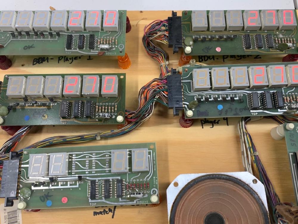
Switch Matrix Inter-Harness Connectors.
Gameplan uses a lot of inter-connectors to make backbox removal easier.
Unfortunately these connectors do not age well, and can cause non-working
switches. Since the switch matrix operates at 5 volts, there's not much
"push" through these connectors, and corrosion can easily dis-able a row
and/or column of switches.
The trick here is to find the correct rectangle round pin connector that
handles the switch matrix. Since we know the switch matrix connector from
the CPU board is at the top edge at J5, we can follow the wire colors to
the correct inter-harness round pin connector. Once this is found, you
have a choice. Either re-pin the connector (time consuming, but probably
the best choice), or mechanically clean the pins. Often a small stainless steel
wire brush can be used to clean the pins... At least as a test to see
if this fixes the switch problems. If it does, label the inter-harness
connector, and keep an eye on the situation. If the problem returns,
then connector pin replacement should be the next step.
The switch matrix connectors on a Gameplan Sharpshooter game.
|
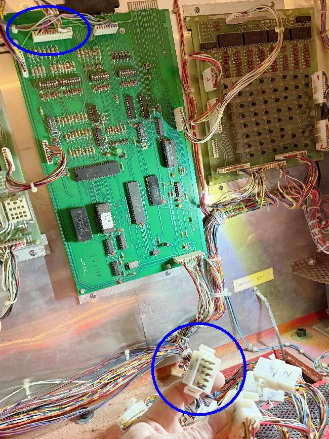
|
3g. When Things Don't Work: Score Display Problems and Fixes.
Gameplan used three different styles of score displays. Most cocktails used the
DDU-1 Dual Display Unit, which had two players worth of score displays
on a single board. Upright pinballs used the BDU-1 Display Unit six digits displays.
A few later games that used the BDU-2 seven digit displays (like
Attila the Hun).
BDU-1 (and BDU-2) General Information.
The BDU-1 has six discrete LED displays making up the six digits. The display
runs completely on 5 volts and has no other power requirements. Because of
this, the score displays are very robust and don't fail often, unlike say
Bally displays that require a separate 190 volt power supply (which fails
often, and burns displays). Gameplan displays can
also be unplugged and plugged in with the game's power on without damage
(not a recommended idea but can be done - don't try that with a 190 volt
Bally display!). On the early Gameplan games like the Cocktail 110 and Sharpshooter,
the ones digit are always zero. Because of this, all the audits and diagnostics
(and the scores) will show the ones digit as a zero.
The six digits are all controlled by six MPS-A13 darlington transistors.
The segments are controlled by three chips (ULN2003, 74LS48, 74LS379)
on the BDU-1 board.
The BDU-2 board is basically the same board as the BDU-1 except it has
seven LED displays instead of six. There is an additional MPU-A13 transistor
and 22 ohm resistor to control the 7th display. But other than that, the BDU-2
is exactly the same as a BDU-1 display board. Hence all diagnostics applying
to the BDU-1 also apply to the BDU-2.
Garbage on the Score Displays.
If you are running a Gameplan MPU without any battery backup, often
garbage will be seen on the score displays at boot-up. This is
a garbage memory problem, since the game does not have any batteries
to store a legitimate high score when the game is turned off. To fix
this problem, install a remote battery pack,
and reboot the game. Then press the Reset button on the MPU board when the game
is in attract mode, and this should clear the high score. Also it's a good idea to go
through the audits and clear out the memory garbage, again
using the MPU's reset button.
Another cause of garbage on the score displays has to do with
the +5 volt power supply. If the power supply's filter capacitor or LM323k
for the +5/12 volts are failing, it can cause garbage on the score displays.
In display test mode using Sharpshooter ROM software:
A 4th player (bottom) BDU-1 score display with locked on 1s and 100s digits. Note this
is affecting the (working) 3rd player display above it. This digit problem on the lower
display was fixed by replacing the corresponding MPS-A13 transistors.
|
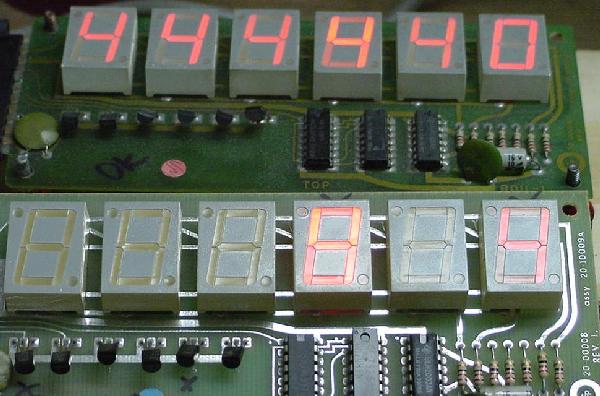
|
Locked on Digits.
The most common problem I have seen with Gameplan score displays are
locked on digits. One or two digits will burn bright and will be
on all the time. This can also affect other (working) score
displays and cause them look like they have a similar problem too. I like to
test displays with just one BDU-1 display connected at a time because of
this problem.
Testing the Q2 MPS-A13 transistor, black DMM lead on the left leg should show
.6 to .8 volts using the diode test. This one is testing as good.
|
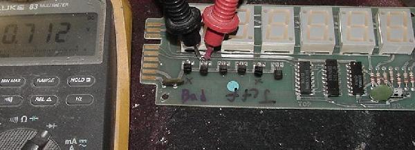
|
Testing the Q2 MPS-A13 transistor, black DMM lead on the right leg should show
1.2 to 1.4 volts using the diode test. This one is testing as good.
|
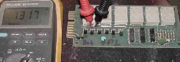
|
A locked on digit is caused by a bad MPS-A13 transistor on the BDU-1
board. There are six MPS-A13 transistor, one for each digit. As facing
the BDU-1 board's component side with the card edge on the left side,
the MPS-A13 transistors are labeled Q1 to Q6 from the left to right.
Here's what each controls:
- Q1 - ones (far right LED digit)
- Q2 - 100,000s (far left LED digit)
- Q3 - 10,000s
- Q4 - 1000s (not installed on credit/ball display)
- Q5 - hundreds (not installed on credit/ball display)
- Q6 - tens
- Q7 - millions (BDU-2 only)
The MPS-A13 transistors can also be tested with a DMM's diode function.
Put the red lead on the center leg, and the black lead on each of the
outside legs. Again as facing the BDU-1 board, the black lead on the
right MPS-A13 leg should show 1.2 to 1.4 volts. Black DMM lead on the
left leg sould show .6 to .8 volts. A null reading or anything outside
this range and the transistor should be replaced. But be aware I have
seen a MPS-A13 test as good, but when replaced it did fix the locked-on
digit problem. In this case I just used the list of above and replaced
the corresponding MPS-A13 and the problem was fixed.
Segment Problems.
The display segments are controlled by the three chips on the BDU-1 board.
The 74LS379 (U3 chip closest to the MPS-A13 transistors) is first in
line from the MPU board. Next is the 74LS48 (U2) and last is the ULN2003 (U1)
and seven 22 ohm resistors. Four bits of data come from the MPU board and
are decoded by the 74LS379 (U3) and 74LS48 (U2) chips. The ULN2003 (U1) then
actually turns the corresponding segments on and off. The 48 and 379 chips
will take the most abuse in the system, with the ULN2003 being protected
by these two chips. This can be followed with a logic probe. Here's the path:
- Bit 1: U3 pin 4 in, U3 pin 2 out. U2 pin 7 in, U2 pin 13 out.
- Bit 2: U3 pin 5 in, U3 pin 7 out. U2 pin 1 in, U2 pin 12 out.
- Bit 3: U3 pin 12 in, U3 pin 10 out. U2 pin 2 in, U2 pin 11 out.
- Bit 4: U3 pin 13 in, U3 pin 15 out. U2 pin 6 in, U2 pin 10 out.
ULN2003 segment controls:
- Segment A = 74LS379 pin 13 to ULN2003 pin 3 (in) and pin 14 (out)
- Segment B = 74LS379 pin 12 to ULN2003 pin 4 (in) and pin 13 (out)
- Segment C = 74LS379 pin 11 to ULN2003 pin 5 (in) and pin 12 (out)
- Segment D = 74LS379 pin 10 to ULN2003 pin 6 (in) and pin 11 (out)
- Segment E = 74LS379 pin 9 to ULN2003 pin 7 (in) and pin 10 (out)
- Segment F = 74LS379 pin 15 to ULN2003 pin 1 (in) and pin 16 (out)
- Segment G = 74LS379 pin 14 to ULN2003 pin 2 (in) and pin 15 (out)
A BDU-1 with a bad 74LS379 and 74LS48 segment chips. The ULN2003 survived
the damage. Most segment problems are related to the 379 and 48 chips.
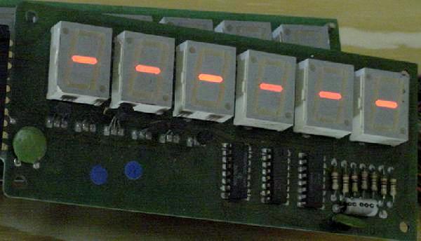
Most segment problems seem to relate to the 74LS48 and 74LS379 chips. I just
repaired two Gameplan BDU-1 displays that had both of these chips blown,
leaving a "-" displayed on all six LED displays at all times (after the
MPU fully booted). Replacing these two chips fixed the problem.
The DDU-1 score displays. These displays have a different card edge connector
than the BDU-1, and hence can not be installed in Gameplan's upright pins wired
with BDU-1 displays.
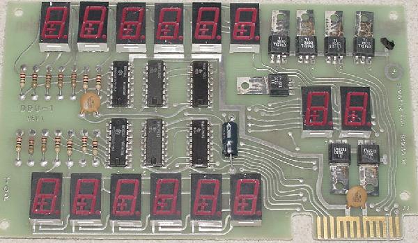
DDU-1 Score Display board.
I have not done any work with the DDU-1, but it is similar in design
to the BDU displays. Differences include using MPS-U45 transistors
instead of MPS-A13's for the digit control. This was done because the U45
transistor are a more robust version of the A13, and
each MPU-U45 controls two LED digits. Here's the break down:
- Q1 - ones (far right LED digit)
- Q2 - tens
- Q3 - hundreds
- Q4 - thousands
- Q5 - ten thousands
- Q6 - hundred thousands
- Q7 - ball/credit displays
The chips that control the segment are a pair of 74LS379 chips, a
pair of 74LS48 chips, and a pair of ULN2003 chips. Again very similar to the BDU unit logic.
Can a BDU-2 be used in place of a BDU-1?
The answer to this is "yes". The seven digit BDU-2 can be used
in place of the six digit BDU-1, plug and play. Just the BDU-2's far left digit will
not display (or even turn on) if the BDU-2 is used in a 6 digit
game that should have a BDU-1 display.
Here's a seven digit BDU-2 display (upper left) running on the test
fixture with Sharp Shooter software (in display test mode.) Note the
seven digit display works fine; just the extra digit on the left
is not lit.
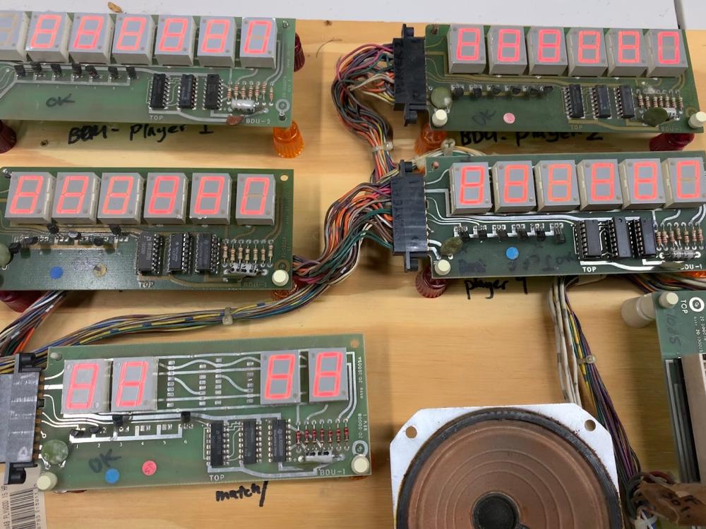
3h. When Things Don't Work: Sound Problems.
One thing I noticed on a lot of Gameplan machines is the boot up sequence
causes the game to make a lot of sound board noise! In particular
Sharpshooter really likes to squeal and yelp at bootup, until the 6th MPU
board LED flash has occured and then the game makes a "ratatattat" machine
gun type noise as its boot-up sound. This is typical of Gameplan pinballs
(but obviously the boot up sounds vary from game title to game title).
MSU Boot-Up LED Flash Codes.
The MSU series of sound boards has a power-on LED flash sequence much
like the MPU board (except the MSU board has eight power-on flashes).
This is because the MSU sounds boards are a computer
within themselves witha 6802 or 6808 processor.
MSU LED N0 Flash.
Check for +5 and +12 volts at the sound board. TP3 is +5 volts, and
TP4 is +12 volts. Check the reset pin of the
6802/6808 pin 40 to make sure the pin is high, meaning the CPU chip is getting
a good reset. Check for a good clock signal at TP6 on the sound board.
If the reset circuit and clock signal are not working the sound board won't
even start to boot.
MSU LED 1st Flash.
Shows that the reset and clock circuits are working and the CPU chip is
trying to run.
MSU LED 2nd Flash.
Shows that the reset and clock circuits are working and the CPU chip is
trying to run.
MSU LED 3rd Flash.
A third LED flash means the ROM chip at U10 and address decoder chip at U7 are good.
No third LED flash means replace the U10 ROM chip.
MSU LED 4rd Flash.
A third LED flash means the ROM chip at U9 and address decoder chip at U7 are good.
No third LED flash means replace the U9 ROM chip.
MSU LED 5th Flash.
A fifth LED flash means the 6810 RAM chip at U8 and address decoder chip at U7 are good.
No fifth LED flash means replace the U8 RAM chip.
MSU LED 6th Flash.
A sixth LED flash means the oscillator circuit at TP5 is good.
No sixth LED flash means replace U1 or the PIA at U5.
MSU LED 7th Flash.
A seventh LED flash means the 6821 PIA at U5 and address decoder U7 is good, and is receiving proper signals
from the MPU board. No seventh LED flash means replace the PIA at U5. Also
try disconnecting J1 from the MSU board and rebooting. If the seventh MSU LED flash
is seen, the problem is on the MPU board.
MSU LED 8th Flash.
An eighth LED flash means the PIA at U12 and address decoder U7 is good, and is receiving proper signals
from the MPU board. No eighth LED flash means replace the PIA at U12.
3i. When Things Don't Work: Miscellaneous Problems and Fixes.
Problem: Strange solenoid and/or lamp and/or souund problems where the game just
does strange and unexplainable things.
Answer:
Replace the MPU board's .01 mfd (103) 16 volt ceramic capacitor to the left and of the red reset
switch and just below the right most bank of DIP switches.
This cap is critical to MPU board timing.
The critical .01 mfd timing capacitor on a MPU-1 and MPU-2 board.
|
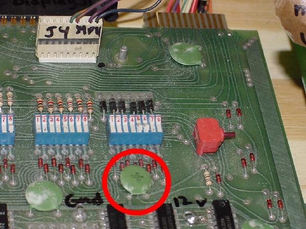
|
Problem: Where do I get a replacement GamePlan flipper Coil?
Answer: Replace a burned flipper coil with the common Bally AQ 25-500 coil.
It works surprisingly well, just like the original coil.
Problem: Can I mix up interconnection plugs when assembling a Gameplan game?
Answer: YES! There is a black pair of plugs and a white pair
of plugs that can be interchanged when assembling a Gameplan pinball.
This will seriously damage the logic of the game if these two sets of
plugs are mixed up.
Problem: I have some broken drop targets on my Sharpshooter game. Where can
I get new ones?
Answer: Unfortunately Gameplan drop targets are not readily available.
But the good news is DataEast drop targets (which are easily available will
work, with a slight modification as the DataEast drop targets are 1/4" longer
than the original Gameplan targets. To do this, first all the targets will
need to be replaced in the drop target bank (no mixing of Gameplan and DE targets).
Then use 1/4" spacers and drop the drop target mechanism down 1/4" below the bottom
of the playfield to compensate for the 1/4" long Dataeast drop targets.
* Go to the Pin Fix-It Index
|
| |